1998 NISSAN PICK-UP engine
[x] Cancel search: enginePage 100 of 1659
BODY & TRIM
SECTIONBT
CONTENTS
PRECAUTIONS......................................................... 1
Service Notice ........................................................ 1
Supplemental Restraint System (SRS) ``AIR
BAG'' (4WD models).............................................. 1
Supplemental Restraint System (SRS) ``AIR
BAG'' (2WD models).............................................. 1
GENERAL SERVICING............................................. 2
Clip and Fastener .................................................. 2
BODY END................................................................ 5
Body Front End ...................................................... 5
Body Rear End ...................................................... 8
DOOR....................................................................... 10
Front Door ............................................................ 10
Rear Door ............................................................ 11
INSTRUMENT PANEL............................................. 12
INTERIOR TRIM...................................................... 15
Side and Floor Trim ............................................. 15
Door Trim ............................................................. 18
Roof Trim ............................................................. 21EXTERIOR............................................................... 24
SEAT........................................................................ 30
Front Seat ............................................................ 30
Heated Seat ......................................................... 32
Rear Seat ............................................................. 33
Jump Seat ............................................................ 34
SUNROOF................................................................ 35
WINDSHIELD AND WINDOWS.............................. 36
Windshield............................................................ 37
Side Window ........................................................ 38
MIRROR................................................................... 39
Door Mirror ........................................................... 39
CAB AND REAR BODY.......................................... 40
Removal ............................................................... 40
Body Mounting ..................................................... 41
BODY ALIGNMENT................................................. 43
Engine Compartment ........................................... 44
Underbody............................................................ 46
.For seat belt, refer to MA and RS section.
.For wiring diagrams of body electrical systems, refer to EL section.BT
Page 140 of 1659
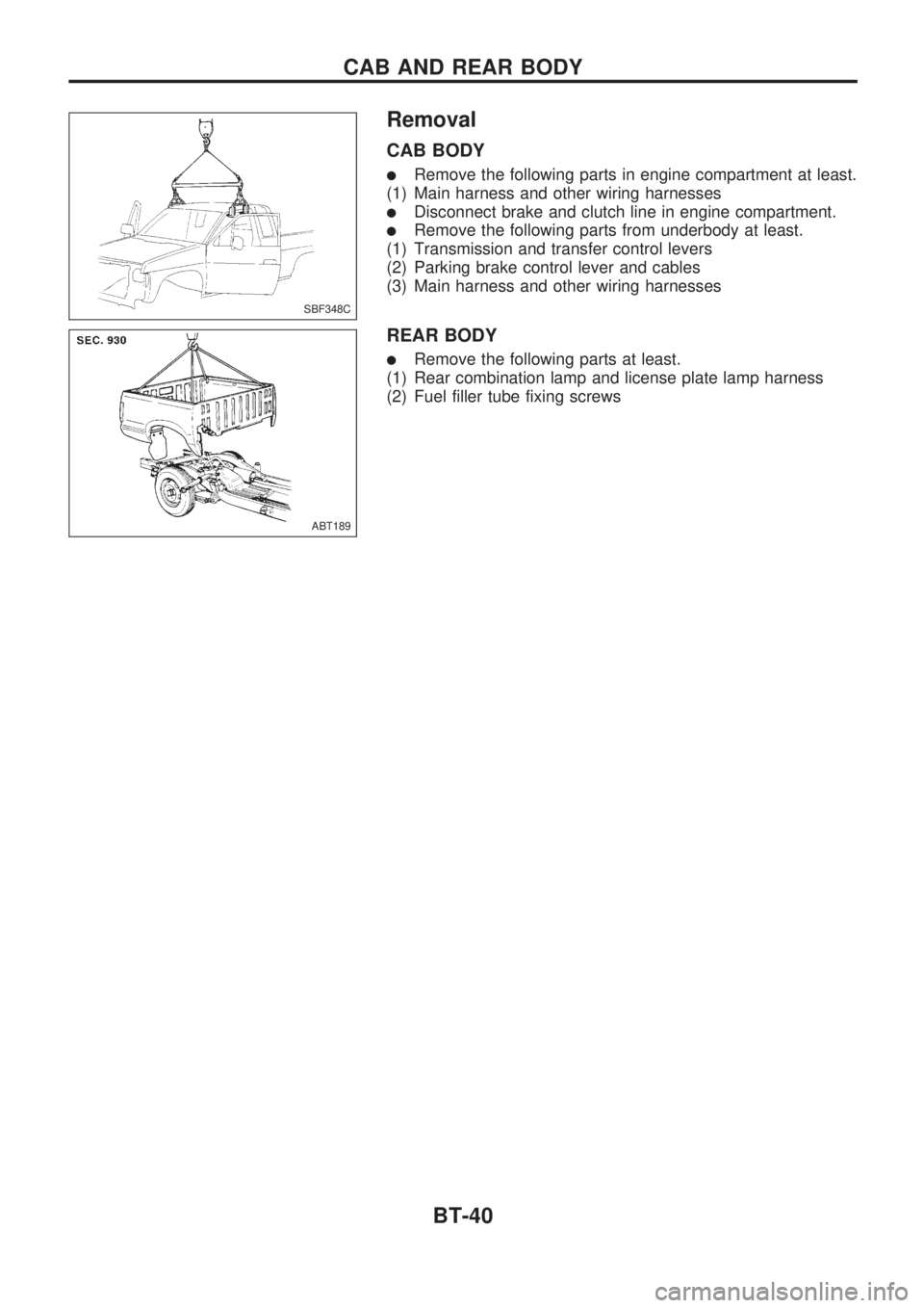
Removal
CAB BODY
lRemove the following parts in engine compartment at least.
(1) Main harness and other wiring harnesses
lDisconnect brake and clutch line in engine compartment.
lRemove the following parts from underbody at least.
(1) Transmission and transfer control levers
(2) Parking brake control lever and cables
(3) Main harness and other wiring harnesses
REAR BODY
lRemove the following parts at least.
(1) Rear combination lamp and license plate lamp harness
(2) Fuel filler tube fixing screws
SBF348C
ABT189
CAB AND REAR BODY
BT-40
Page 144 of 1659
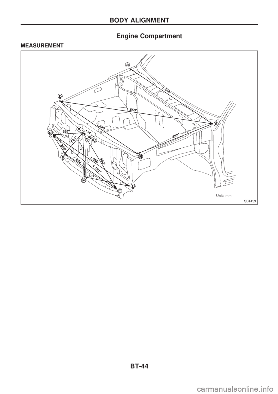
Engine Compartment
MEASUREMENT
SBT459
BODY ALIGNMENT
BT-44
Page 145 of 1659

MEASUREMENT POINTS
SBT460
BODY ALIGNMENT
Engine Compartment (Cont'd)
BT-45
Page 150 of 1659
ENGINE CONTROL SYSTEM
SECTION
EC
CONTENTS
DIAGNOSTIC TROUBLE CODE INDEX................... 1
Alphabetical & Numerical Index for DTC
(KA engine) ............................................................ 1
PRECAUTIONS AND PREPARATION..................... 2
Special Service Tools ............................................ 2
Commercial Service Tool....................................... 4
Supplemental Restraint System (SRS) ``AIR
BAG'' (4WD models).............................................. 4
Supplemental Restraint System (SRS) ``AIR
BAG'' (2WD models).............................................. 4
KA
PRECAUTIONS AND PREPARATION..................... 5
Engine Fuel & Emission Control System .............. 5
Precautions ............................................................ 6
ENGINE AND EMISSION CONTROL OVERALL
SYSTEM..................................................................... 8
Circuit Diagram ...................................................... 8
System Diagram .................................................... 9
ECCS Component Parts Location ....................... 10
Vacuum Hose Drawing ........................................ 12
System Chart ....................................................... 13
ENGINE AND EMISSION BASIC CONTROL
SYSTEM DESCRIPTION..................................... 14
Multiport Fuel Injection (MFI) System.................. 14
Distributor Ignition (DI) System............................ 17
Air Conditioning Cut Control ................................ 18
Fuel Cut Control (at no load & high engine
speed) .................................................................. 18
EVAPORATIVE EMISSION SYSTEM..................... 19
Description ........................................................... 19
Inspection ............................................................. 19POSITIVE CRANKCASE VENTILATION................ 21
Description ........................................................... 21
Inspection ............................................................. 21
BASIC SERVICE PROCEDURE............................. 22
Fuel Pressure Release ........................................ 22
Fuel Pressure Check ........................................... 22
Injector Removal and Installation ........................ 23
Fast Idle Cam (FIC) Inspection and
Adjustment ........................................................... 24
Idle Speed/Ignition Timing/Idle Mixture Ratio
Adjustment ........................................................... 25
ON BOARD DIAGNOSTIC SYSTEM
DESCRIPTION......................................................... 36
Introduction .......................................................... 36
Diagnostic Trouble Code (DTC) .......................... 36
Malfunction Indicator Lamp (MIL) ........................ 38
CONSULT ............................................................ 45
TROUBLE DIAGNOSIS - Introduction.................. 54
Introduction .......................................................... 54
Diagnostic Worksheet .......................................... 54
TROUBLE DIAGNOSIS - Work Flow..................... 56
Work Flow ............................................................ 56
Description for Work Flow ................................... 57
TROUBLE DIAGNOSIS - Basic Inspection.......... 58
Basic Inspection ................................................... 58
TROUBLE DIAGNOSIS - General Description..... 61
Fail-Safe Chart ..................................................... 61
Symptom Matrix Chart ......................................... 62
CONSULT Reference Value in Data Monitor
Mode .................................................................... 64
Major Sensor Reference Graph in Data
Monitor Mode ....................................................... 66
ECM Terminals and Reference Value ................. 68
EC
Page 151 of 1659

TROUBLE DIAGNOSIS FOR POWER SUPPLY.... 75
Main Power Supply and Ground Circuit .............. 75
TROUBLE DIAGNOSIS FOR ``CAMSHAFT
POSI SEN'' (DTC 11).............................................. 82
Camshaft Position Sensor (CMPS) ..................... 82
TROUBLE DIAGNOSIS FOR ``MASS AIR
FLOW SEN'' (DTC 12)............................................ 89
Mass Air Flow Sensor (MAFS) ............................ 89
TROUBLE DIAGNOSIS FOR ``COOLANT TEMP
SEN'' (DTC 13)........................................................ 95
Engine Coolant Temperature Sensor (ECTS) ..... 95
TROUBLE DIAGNOSIS FOR ``IGN SIGNAL-
PRIMARY'' (DTC 21)............................................... 99
Ignition Signal ...................................................... 99
TROUBLE DIAGNOSIS FOR ``OVER HEAT''
(DTC 28)................................................................. 106
Overheat ............................................................ 106
TROUBLE DIAGNOSIS FOR ``INT AIR TEMP
SEN'' (DTC 41)...................................................... 109
Intake Air Temperature Sensor ......................... 109
TROUBLE DIAGNOSIS FOR ``THROTTLE POSI
SEN'' (DTC 43)...................................................... 113
Throttle Position Sensor .................................... 113
TROUBLE DIAGNOSIS FOR
NON-DETECTABLE ITEMS.................................. 118
Vehicle Speed Sensor (VSS) ............................ 118
Heated Oxygen Sensor (HO2S)
- LHD Models - .................................................. 123
Heated Oxygen Sensor Heater
- LHD Models - .................................................. 127
Idle Air Control Valve (IACV) - Auxiliary Air
Control (AAC) Valve .......................................... 131
Neutral Position Switch ...................................... 136
EVAP Canister Purge Control Solenoid Valve .. 140
Injector ............................................................... 144
Start Signal ........................................................ 149
Fuel Pump.......................................................... 151
Power Steering Oil Pressure Switch ................. 157
Swirl Control Valve Control Solenoid Valve ...... 161
IACV-FICD Solenoid Valve ................................ 168
MIL & Data Link Connectors ............................. 173
TD
INJECTION SYSTEM............................................ 176
Fuel System ....................................................... 176
INJECTION PUMP................................................. 178
Inspection ........................................................... 178
Removal ............................................................. 178
Installation and Adjustment................................ 180
Disassembly ....................................................... 183
Load Timer Adjustment...................................... 183
Start Q Adjustment Lever .................................. 184
INJECTION NOZZLE............................................. 186Removal and Installation ................................... 186
Disassembly ....................................................... 186
Inspection ........................................................... 187
Cleaning ............................................................. 187
Assembly............................................................ 189
Test and Adjustment .......................................... 189
FUEL SYSTEM CHECK........................................ 191
Bleeding Fuel System ........................................ 191
Bleeding Fuel Filter ............................................ 192
Checking Priming Pump .................................... 192
Checking Fuel Filter Switch ............................... 192
POSITIVE CRANKCASE VENTILATION.............. 193
Description ......................................................... 193
Inspection ........................................................... 193
QUICK-GLOW SYSTEM........................................ 194
Component Parts Location ................................ 194
Circuit Diagram .................................................. 195
Description ......................................................... 196
Wiring Diagram .................................................. 197
Glow Control Unit Circuit Inspection (For Cold
Areas)................................................................. 203
Glow Control Unit Circuit Inspection (Except
for Cold Areas)................................................... 206
Component Inspection ....................................... 208
EGR SYSTEM........................................................ 210
Component Parts Location ................................ 210
Description ......................................................... 211
Operation ........................................................... 212
Wiring Diagram .................................................. 213
System Inspection.............................................. 217
Component Inspection ....................................... 218
SOLENOID TIMER................................................ 220
Description ......................................................... 220
Operation ........................................................... 220
Wiring Diagram .................................................. 222
Inspection ........................................................... 224
FUEL CUT SYSTEM.............................................. 225
Wiring Diagram .................................................. 225
FUEL HEATER SYSTEM...................................... 226
Description ......................................................... 226
Wiring Diagram .................................................. 227
System Inspection.............................................. 228
Component Inspection ....................................... 228
FAST IDLE CONTROL CIRCUIT.......................... 230
Wiring Diagram .................................................. 230
Electrical Components Inspection ..................... 231
KA
SERVICE DATA AND SPECIFICATIONS (SDS). 232
General Specifications ....................................... 232
Inspection and Adjustment ................................ 232
Page 153 of 1659
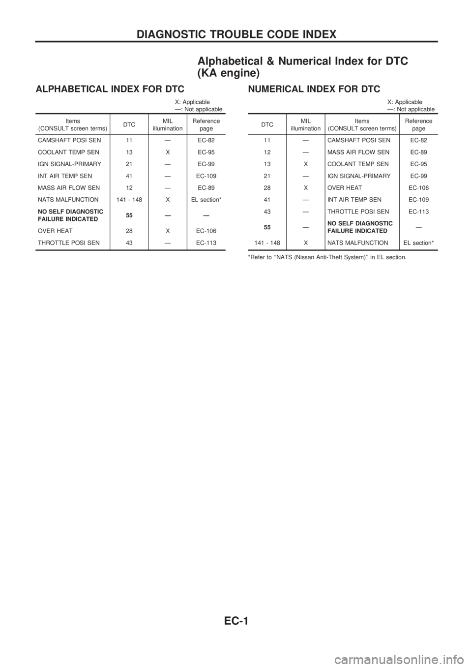
Alphabetical & Numerical Index for DTC
(KA engine)
ALPHABETICAL INDEX FOR DTC
X: Applicable
Ð: Not applicable
Items
(CONSULT screen terms)DTCMIL
illuminationReference
page
CAMSHAFT POSI SEN 11 Ð EC-82
COOLANT TEMP SEN 13 X EC-95
IGN SIGNAL-PRIMARY 21 Ð EC-99
INT AIR TEMP SEN 41 Ð EC-109
MASS AIR FLOW SEN 12 Ð EC-89
NATS MALFUNCTION 141 - 148 X EL section*
NO SELF DIAGNOSTIC
FAILURE INDICATED55 Ð Ð
OVER HEAT 28 X EC-106
THROTTLE POSI SEN 43 Ð EC-113
NUMERICAL INDEX FOR DTC
X: Applicable
Ð: Not applicable
DTCMIL
illuminationItems
(CONSULT screen terms)Reference
page
11 Ð CAMSHAFT POSI SEN EC-82
12 Ð MASS AIR FLOW SEN EC-89
13 X COOLANT TEMP SEN EC-95
21 Ð IGN SIGNAL-PRIMARY EC-99
28 X OVER HEAT EC-106
41 Ð INT AIR TEMP SEN EC-109
43 Ð THROTTLE POSI SEN EC-113
55 ÐNO SELF DIAGNOSTIC
FAILURE INDICATEDÐ
141 - 148 X NATS MALFUNCTION EL section*
*Refer to ``NATS (Nissan Anti-Theft System)'' in EL section.
DIAGNOSTIC TROUBLE CODE INDEX
EC-1
Page 154 of 1659
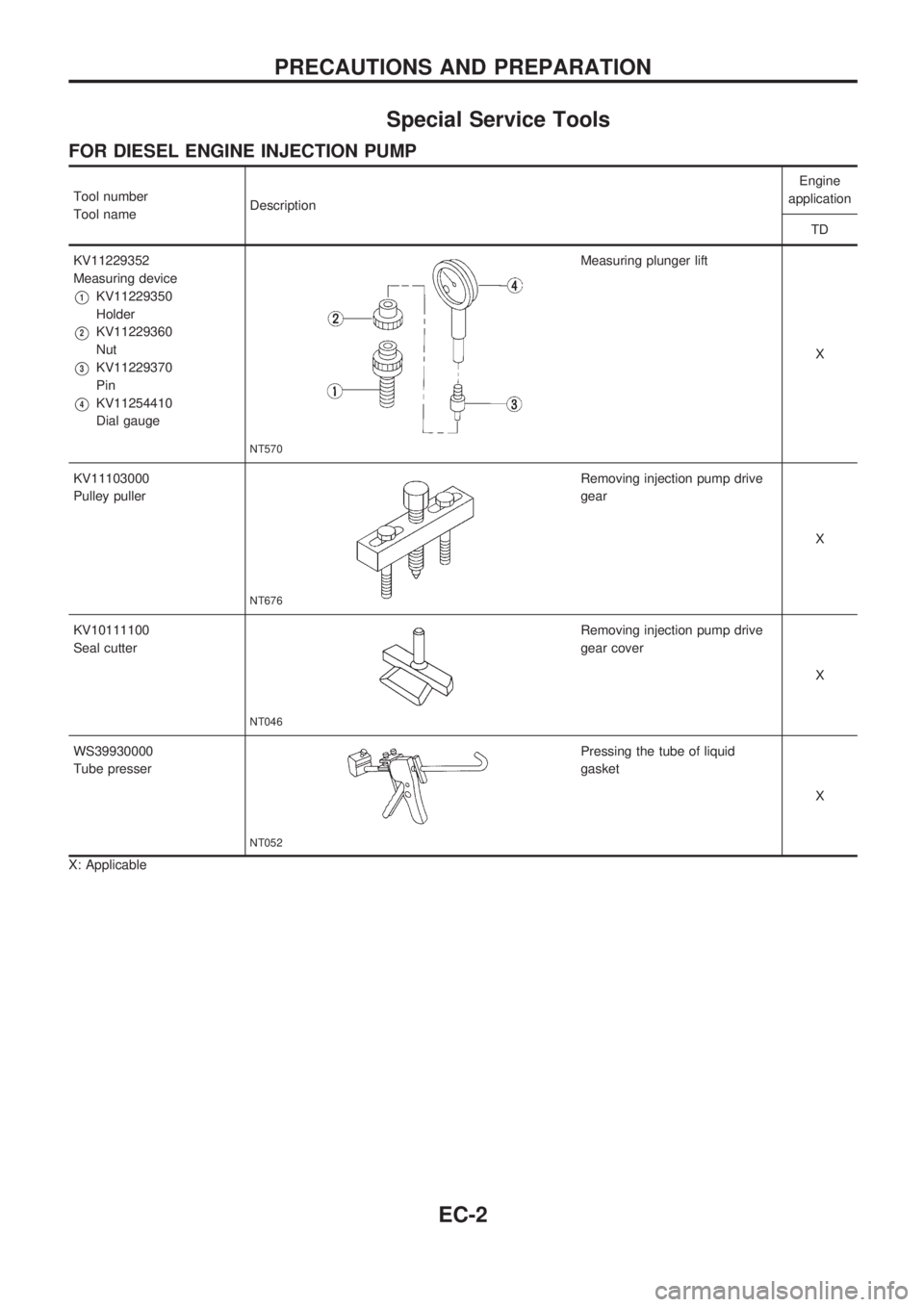
Special Service Tools
FOR DIESEL ENGINE INJECTION PUMP
Tool number
Tool nameDescriptionEngine
application
TD
KV11229352
Measuring device
V1KV11229350
Holder
V2KV11229360
Nut
V3KV11229370
Pin
V4KV11254410
Dial gauge
NT570
Measuring plunger lift
X
KV11103000
Pulley puller
NT676
Removing injection pump drive
gear
X
KV10111100
Seal cutter
NT046
Removing injection pump drive
gear cover
X
WS39930000
Tube presser
NT052
Pressing the tube of liquid
gasket
X
X: Applicable
PRECAUTIONS AND PREPARATION
EC-2