1998 NISSAN PICK-UP engine
[x] Cancel search: enginePage 812 of 1659
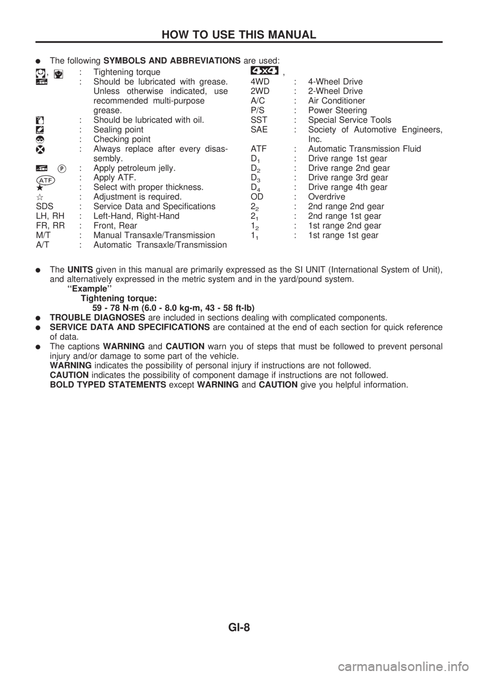
lThe followingSYMBOLS AND ABBREVIATIONSare used:
,: Tightening torque
: Should be lubricated with grease.
Unless otherwise indicated, use
recommended multi-purpose
grease.
: Should be lubricated with oil.
: Sealing point
: Checking point
: Always replace after every disas-
sembly.
VP: Apply petroleum jelly.
: Apply ATF.
.: Select with proper thickness.
>: Adjustment is required.
SDS : Service Data and Specifications
LH, RH : Left-Hand, Right-Hand
FR, RR : Front, Rear
M/T : Manual Transaxle/Transmission
A/T : Automatic Transaxle/Transmission
,
4WD : 4-Wheel Drive
2WD : 2-Wheel Drive
A/C : Air Conditioner
P/S : Power Steering
SST : Special Service Tools
SAE : Society of Automotive Engineers,
Inc.
ATF : Automatic Transmission Fluid
D
1: Drive range 1st gear
D
2: Drive range 2nd gear
D
3: Drive range 3rd gear
D
4: Drive range 4th gear
OD : Overdrive
2
2: 2nd range 2nd gear
2
1: 2nd range 1st gear
1
2: 1st range 2nd gear
1
1: 1st range 1st gear
lTheUNITSgiven in this manual are primarily expressed as the SI UNIT (International System of Unit),
and alternatively expressed in the metric system and in the yard/pound system.
``Example''
Tightening torque:
59 - 78 N´m (6.0 - 8.0 kg-m, 43 - 58 ft-lb)
lTROUBLE DIAGNOSESare included in sections dealing with complicated components.
lSERVICE DATA AND SPECIFICATIONSare contained at the end of each section for quick reference
of data.
lThe captionsWARNINGandCAUTIONwarn you of steps that must be followed to prevent personal
injury and/or damage to some part of the vehicle.
WARNINGindicates the possibility of personal injury if instructions are not followed.
CAUTIONindicates the possibility of component damage if instructions are not followed.
BOLD TYPED STATEMENTSexceptWARNINGandCAUTIONgive you helpful information.
HOW TO USE THIS MANUAL
GI-8
Page 819 of 1659
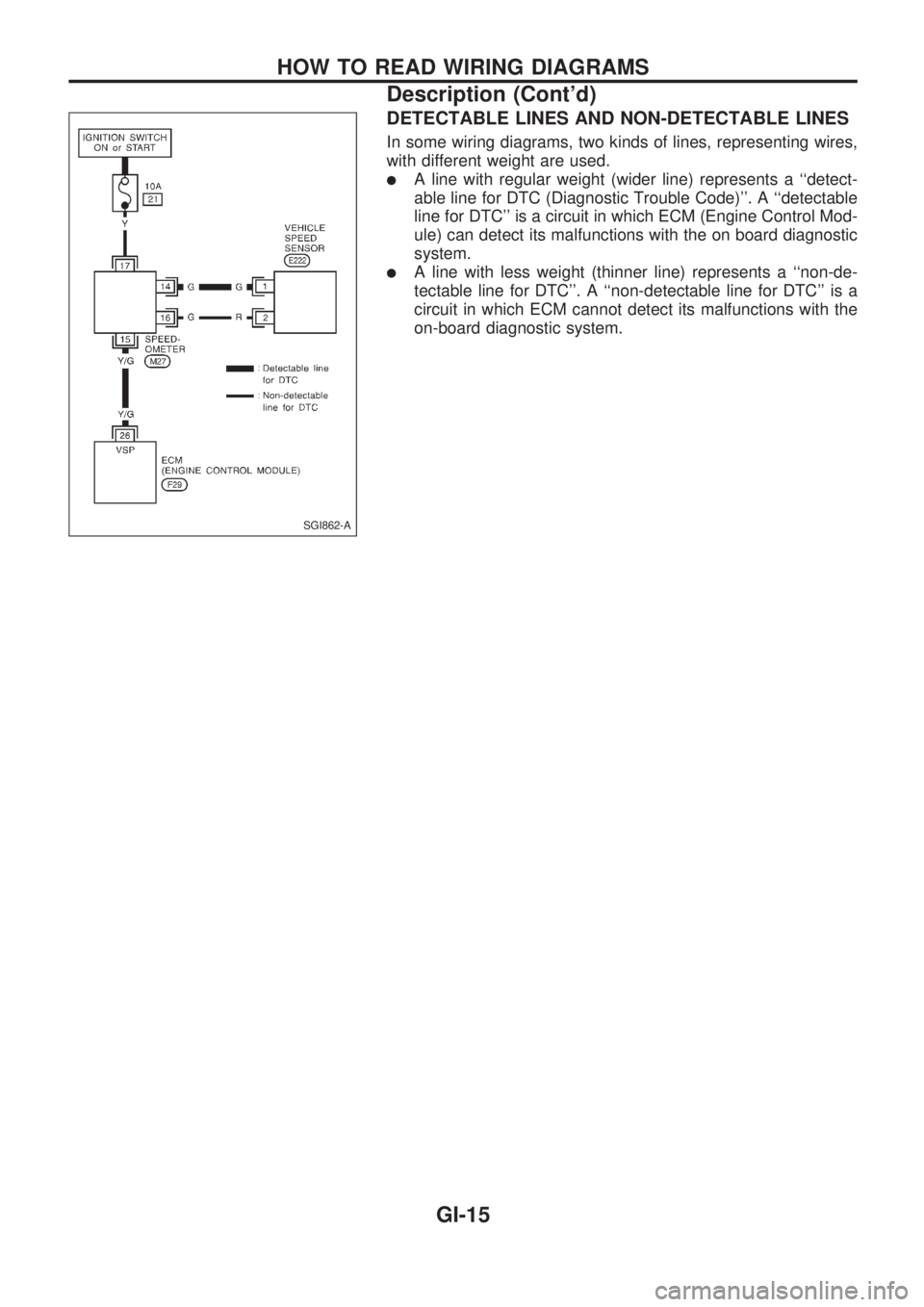
DETECTABLE LINES AND NON-DETECTABLE LINES
In some wiring diagrams, two kinds of lines, representing wires,
with different weight are used.
lA line with regular weight (wider line) represents a ``detect-
able line for DTC (Diagnostic Trouble Code)''. A ``detectable
line for DTC'' is a circuit in which ECM (Engine Control Mod-
ule) can detect its malfunctions with the on board diagnostic
system.
lA line with less weight (thinner line) represents a ``non-de-
tectable line for DTC''. A ``non-detectable line for DTC'' is a
circuit in which ECM cannot detect its malfunctions with the
on-board diagnostic system.
SGI862-A
HOW TO READ WIRING DIAGRAMS
Description (Cont'd)
GI-15
Page 825 of 1659
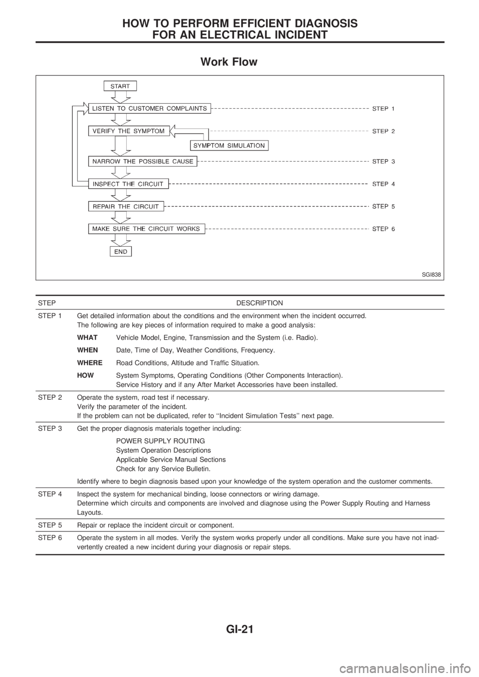
Work Flow
STEP DESCRIPTION
STEP 1 Get detailed information about the conditions and the environment when the incident occurred.
The following are key pieces of information required to make a good analysis:
WHATVehicle Model, Engine, Transmission and the System (i.e. Radio).
WHENDate, Time of Day, Weather Conditions, Frequency.
WHERERoad Conditions, Altitude and Traffic Situation.
HOWSystem Symptoms, Operating Conditions (Other Components Interaction).
Service History and if any After Market Accessories have been installed.
STEP 2 Operate the system, road test if necessary.
Verify the parameter of the incident.
If the problem can not be duplicated, refer to ``Incident Simulation Tests'' next page.
STEP 3 Get the proper diagnosis materials together including:
POWER SUPPLY ROUTING
System Operation Descriptions
Applicable Service Manual Sections
Check for any Service Bulletin.
Identify where to begin diagnosis based upon your knowledge of the system operation and the customer comments.
STEP 4 Inspect the system for mechanical binding, loose connectors or wiring damage.
Determine which circuits and components are involved and diagnose using the Power Supply Routing and Harness
Layouts.
STEP 5 Repair or replace the incident circuit or component.
STEP 6 Operate the system in all modes. Verify the system works properly under all conditions. Make sure you have not inad-
vertently created a new incident during your diagnosis or repair steps.
SGI838
HOW TO PERFORM EFFICIENT DIAGNOSIS
FOR AN ELECTRICAL INCIDENT
GI-21
Page 826 of 1659
Incident Simulation Tests
INTRODUCTION
Sometimes the symptom is not present when the vehicle is brought in for service. If possible, re-create the
conditions present at the time of the incident. Doing so may help avoid a No Trouble Found Diagnosis. The
following section illustrates ways to simulate the conditions/environment under which the owner experiences
an electrical incident.
The section is broken into the six following topics:
lVehicle vibration
lHeat sensitive
lFreezing
lWater intrusion
lElectrical load
lCold or hot start up
Get a thorough description of the incident from the customer. It is important for simulating the conditions of
the problem.
VEHICLE VIBRATION
The problem may occur or become worse while driving on a rough road or when engine is vibrating (idle
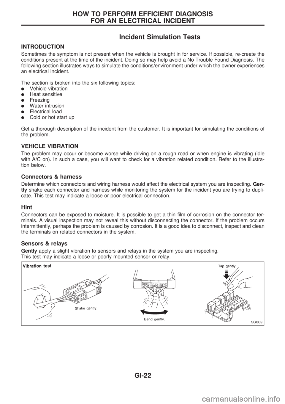
with A/C on). In such a case, you will want to check for a vibration related condition. Refer to the illustra-
tion below.
Connectors & harness
Determine which connectors and wiring harness would affect the electrical system you are inspecting.Gen-
tlyshake each connector and harness while monitoring the system for the incident you are trying to dupli-
cate. This test may indicate a loose or poor electrical connection.
Hint
Connectors can be exposed to moisture. It is possible to get a thin film of corrosion on the connector ter-
minals. A visual inspection may not reveal this without disconnecting the connector. If the problem occurs
intermittently, perhaps the problem is caused by corrosion. It is a good idea to disconnect, inspect and clean
the terminals on related connectors in the system.
Sensors & relays
Gentlyapply a slight vibration to sensors and relays in the system you are inspecting.
This test may indicate a loose or poorly mounted sensor or relay.
SGI839
HOW TO PERFORM EFFICIENT DIAGNOSIS
FOR AN ELECTRICAL INCIDENT
GI-22
Page 827 of 1659
Engine compartment
There are several reasons a vehicle or engine vibration could
cause an electrical complaint. Some of the things to check for
are:
lConnectors not fully seated.
lWiring harness not long enough and is being stressed due
to engine vibrations or rocking.
lWires laying across brackets or moving components.
lLoose, dirty or corroded ground wires.
lWires routed too close to hot components.
To inspect components under the hood, start by verifying the
integrity of ground connections. (Refer to GROUND INSPEC-
TION described later.) First check that the system is properly
grounded. Then check for loose connection bygently shaking
the wiring or components as previously explained. Using the
wiring diagrams inspect the wiring for continuity.
Behind the instrument panel
An improperly routed or improperly clamped harness can
become pinched during accessory installation. Vehicle vibration
can aggravate a harness which is routed along a bracket or near
a screw.
Under seating areas
An unclamped or loose harness can cause wiring to be pinched
by seat components (such as slide guides) during vehicle vibra-
tion. If the wiring runs under seating areas, inspect wire routing
for possible damage or pinching.
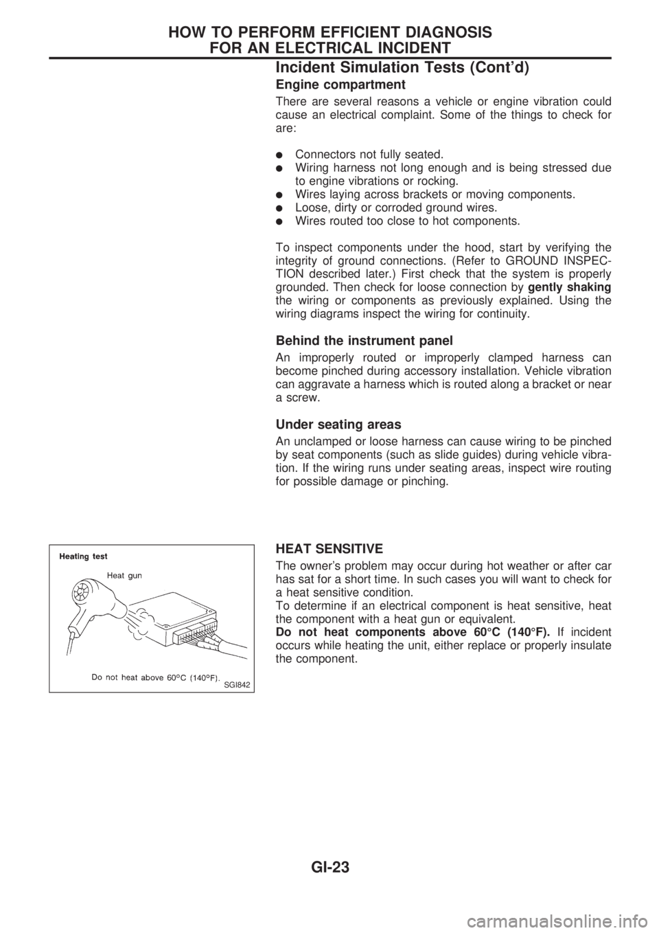
HEAT SENSITIVE
The owner's problem may occur during hot weather or after car
has sat for a short time. In such cases you will want to check for
a heat sensitive condition.
To determine if an electrical component is heat sensitive, heat
the component with a heat gun or equivalent.
Do not heat components above 60ÉC (140ÉF).If incident
occurs while heating the unit, either replace or properly insulate
the component.
SGI842
HOW TO PERFORM EFFICIENT DIAGNOSIS
FOR AN ELECTRICAL INCIDENT
Incident Simulation Tests (Cont'd)
GI-23
Page 837 of 1659

KEY TO SYMBOLS SIGNIFYING MEASUREMENTS OR PROCEDURES
Symbol Symbol explanation Symbol Symbol explanation
Check after disconnecting the connector
to be measured.Procedure with CONSULT
Check after connecting the connector to
be measured.Procedure without CONSULT
Insert key into ignition switch.A/C switch is ``OFF''.
Remove key from ignition switch.A/C switch is ``ON''.
Turn ignition switch to ``OFF'' position.Fan switch is ``ON''. (At any position
except for ``OFF'' position)
Turn ignition switch to ``ON'' position.Fan switch is ``OFF''.
Turn ignition switch to ``START'' position.Apply positive voltage from battery with
fuse directly to components.
Turn ignition switch from ``OFF'' to ``ACC''
position.Drive vehicle.
Turn ignition switch from ``ACC'' to ``OFF''
position.Disconnect battery negative cable.
Turn ignition switch from ``OFF'' to ``ON''
position.Depress brake pedal.
Turn ignition switch from ``ON'' to ``OFF''
position.Release brake pedal.
Do not start engine, or check with engine
stopped.Depress accelerator pedal.
Start engine, or check with engine run-
ning.Release accelerator pedal.
Apply parking brake.
Pin terminal check for SMJ type ECM
and TCM control unit connectors.
For details regarding the terminal
arrangement, refer to the foldout page.Release parking brake.
Check after engine is warmed up suffi-
ciently.
Voltage should be measured with a volt-
meter.
Circuit resistance should be measured
with an ohmmeter.
Current should be measured with an
ammeter.
HOW TO FOLLOW FLOW CHART IN TROUBLE DIAGNOSES
How to Follow This Flow Chart (Cont'd)
GI-33
Page 841 of 1659
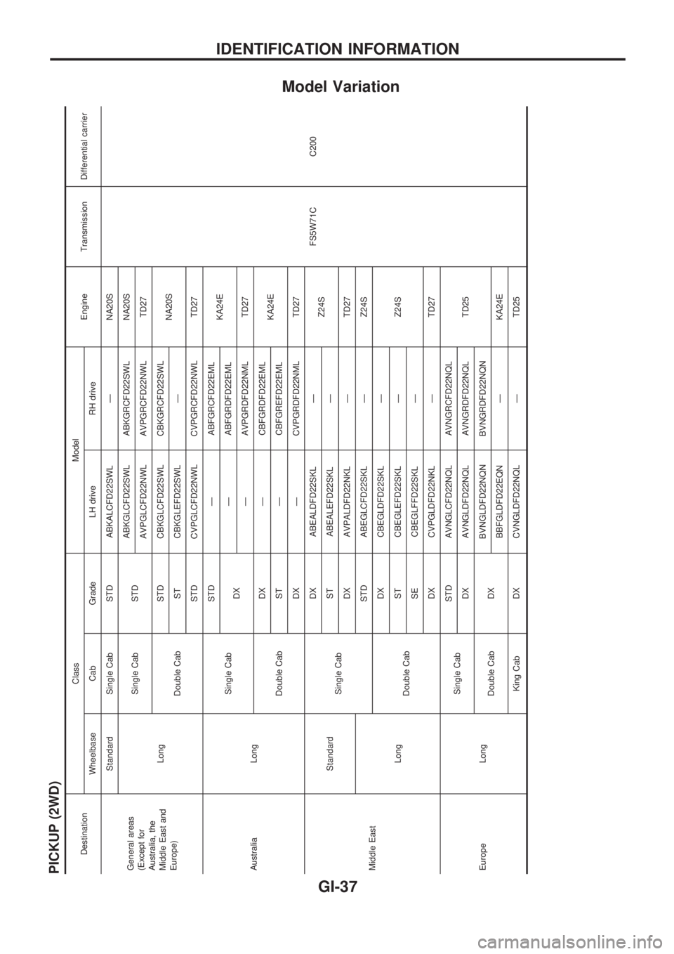
Model Variation
PICKUP (2WD)
DestinationClass Model
Engine Transmission Differential carrier
Wheelbase Cab Grade LH drive RH drive
General areas
(Except for
Australia, the
Middle East and
Europe)Standard Single Cab STD ABKALCFD22SWL Ð NA20S
FS5W71C C200 LongSingle Cab STDABKGLCFD22SWL ABKGRCFD22SWL NA20S
AVPGLCFD22NWL AVPGRCFD22NWL TD27
Double CabSTD CBKGLCFD22SWL CBKGRCFD22SWL
NA20S
ST CBKGLEFD22SWL Ð
STD CVPGLCFD22NWL CVPGRCFD22NWL TD27
Australia LongSingle CabSTD Ð ABFGRCFD22EML
KA24E
DXÐ ABFGRDFD22EML
Ð AVPGRDFD22NML TD27
Double CabDX Ð CBFGRDFD22EML
KA24E
ST Ð CBFGREFD22EML
DX Ð CVPGRDFD22NML TD27
Middle EastStandard
Single CabDX ABEALDFD22SKL Ð
Z24S
ST ABEALEFD22SKL Ð
DX AVPALDFD22NKL Ð TD27
LongSTD ABEGLCFD22SKL Ð Z24S
Double CabDX CBEGLDFD22SKL Ð
Z24S ST CBEGLEFD22SKL Ð
SE CBEGLFFD22SKL Ð
DX CVPGLDFD22NKL Ð TD27
Europe LongSingle CabSTD AVNGLCFD22NQL AVNGRCFD22NQL
TD25 DX AVNGLDFD22NQL AVNGRDFD22NQL
Double Cab DXBVNGLDFD22NQN BVNGRDFD22NQN
BBFGLDFD22EQN Ð KA24E
King Cab DX CVNGLDFD22NQL Ð TD25
IDENTIFICATION INFORMATION
GI-37
Page 842 of 1659
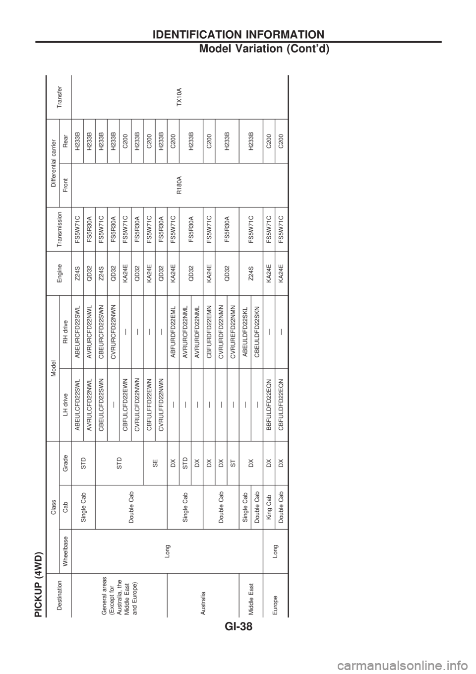
PICKUP (4WD)DestinationClass Model
Engine TransmissionDifferential carrier
Transfer
Wheelbase Cab Grade LH drive RH drive Front Rear
General areas
(Except for
Australia, the
Middle East
and Europe)
LongSingle Cab STDABEULCFD22SWL ABEURCFD22SWL Z24S FS5W71C
R180AH233B
TX10A AVRULCFD22NWL AVRURCFD22NWL QD32 FS5R30A H233B
Double CabSTDCBEULCFD22SWN CBEURCFD22SWN Z24S FS5W71C H233B
Ð CVRURCFD22NWN QD32 FS5R30A H233B
CBFULCFD22EWN Ð KA24E FS5W71C C200
CVRULCFD22NWN Ð QD32 FS5R30A H233B
SECBFULFFD22EWN Ð KA24E FS5W71C C200
CVRULFFD22NWN Ð QD32 FS5R30A H233B
AustraliaSingle CabDX Ð ABFURDFD22EML KA24E FS5W71C C200
STD Ð AVRURCFD22NML
QD32 FS5R30A H233B
DX Ð AVRURDFD22NML
Double CabDX Ð CBFURDFD22EMN KA24E FS5W71C C200
DX Ð CVRURDFD22NMN
QD32 FS5R30A H233B
ST Ð CVRUREFD22NMN
Middle EastSingle Cab
DXÐ ABEULDFD22SKL
Z24S FS5W71C H233B
Double Cab Ð CBEULDFD22SKN
Europe LongKing Cab DX BBFULDFD22EQN Ð KA24E FS5W71C C200
Double Cab DX CBFULDFD22EQN Ð KA24E FS5W71C C200
IDENTIFICATION INFORMATION
Model Variation (Cont'd)
GI-38