Page 910 of 1659

Diagnostic Procedure 2
EXCEPT FOR KA ENGINE MODELS
SYMPTOM: Magnet clutch does not engage when A/C
switch and fan switch are ON.
lPerform PRELIMINARY CHECK 1 before referring to the
following flow chart.
CHECK POWER SUPPLY FOR COM-
PRESSOR.
Disconnect compressor harness connec-
tor.
Do approx. 12 volts exist between com-
pressor harness terminal No.
V1and body
ground?
No
cYes
Check the following.
lMagnet clutch coillThermal protector (Except
for the Middle East)
NG
Replace magnet clutch.
Refer to HA-60.
Note
Check circuit continuity between A/C relay
harness terminal No.
V5and compressor
harness terminal No.
V1.
Continuity should exist.
If OK, check harness for short.
OK
CHECK POWER SUPPLY FOR A/C
RELAY.
Do approx. 12 volts exist between A/C
relay harness terminal No.
V3and body
ground?
Yes
cNo
Check power supply circuit
and 7.5A fuse (No.
21 ,
located in the fuse block).
(Refer to ``POWER SUP-
PLY ROUTING'' in EL sec-
tion and Wiring Diagram.)
CHECK POWER SUPPLY FOR A/C
RELAY.
Do approx. 12 volts exist between A/C
relay harness terminal No.
V1and body
ground?
No
cYes
Check power supply circuit
and 7.5A fuse (No.
21 ,
located in the fuse block).
(Refer to ``POWER SUP-
PLY ROUTING'' in EL sec-
tion and Wiring Diagram.)
CHECK A/C RELAY AFTER DISCON-
NECTING IT.
Refer to HA-44.
OK
cNG
Replace A/C relay.
Reconnect A/C relay.
Note
Check circuit continuity between A/C relay
harness terminal No.
V2and triple-pres-
sure switch harness terminal No.
V4.
Continuity should exist.
If OK, check harness for short.
OK
VA(Go to next page.)
Note:
If the result is NG after checking circuit continuity, repair harness or con-
nector.
RHA325G
RHA748FD
RHA359G
RHA375G
RHA327GA
.
.
.
.
.
.
.
.
TROUBLE DIAGNOSES
HA-39
Page 912 of 1659

FOR KA ENGINE MODELS
SYMPTOM: Magnet clutch does not engage when A/C
switch and fan switch are ON.
lPerform PRELIMINARY CHECK 1 before referring to the
following flow chart.
CHECK POWER SUPPLY FOR COM-
PRESSOR.
Disconnect compressor harness connec-
tor.
Do approx. 12 volts exist between com-
pressor harness terminal No.
V1and body
ground?
No
cYes
Check the following.
lMagnet clutch coil
lThermal protector
NG
Replace magnet clutch.
Refer to HA-60.
Note
Check circuit continuity between A/C relay
harness terminal No.
V5and compressor
harness terminal No.
V1.
Continuity should exist.
If OK, check harness for short.
OK
CHECK POWER SUPPLY FOR A/C
RELAY.
Do approx. 12 volts exist between A/C
relay harness terminal No.
V3and body
ground?
Yes
cNo
Check power supply circuit
and 7.5A fuse (No.
21 ,
located in the fuse block).
(Refer to ``POWER SUP-
PLY ROUTING'' in EL sec-
tion and Wiring Diagram.)
CHECK POWER SUPPLY FOR A/C
RELAY.
Do approx. 12 volts exist between A/C
relay harness terminal No.
V1and body
ground?
Yes
cNo
Check power supply circuit
and 7.5A fuse (No.
21 ,
located in the fuse block).
(Refer to ``POWER SUP-
PLY ROUTING'' in EL sec-
tion and Wiring Diagram.)
CHECK A/C RELAY AFTER DISCON-
NECTING IT.
Refer to HA-44.
OK
cNG
Replace A/C relay.
Reconnect A/C relay.
VA
(Go to next page.)
Note:
If the result is NG after checking circuit continuity, repair harness or con-
nector.
RHA333G
RHA334G
RHA359G
RHA375G
.
.
.
.
.
.
.
TROUBLE DIAGNOSES
Diagnostic Procedure 2 (Cont'd)
HA-41
Page 919 of 1659

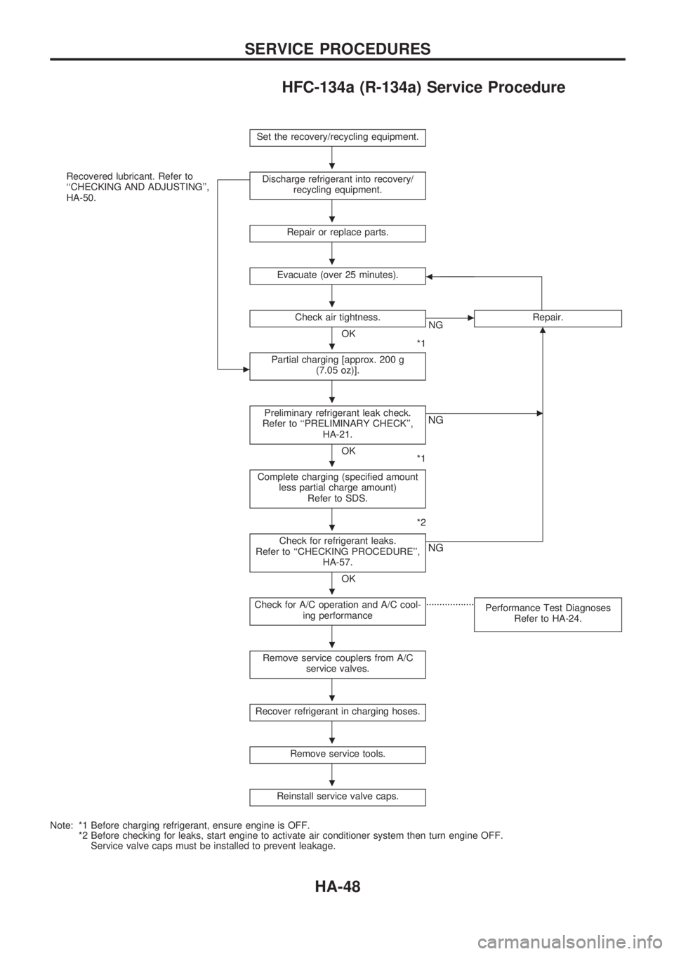
HFC-134a (R-134a) Service Procedure
Set the recovery/recycling equipment.
Recovered lubricant. Refer to
``CHECKING AND ADJUSTING'',
HA-50.
c
Discharge refrigerant into recovery/
recycling equipment.
Repair or replace parts.
Evacuate (over 25 minutes).b
Check air tightness.
OK
*1
cNGRepair.m
Partial charging [approx. 200 g
(7.05 oz)].
Preliminary refrigerant leak check.
Refer to ``PRELIMINARY CHECK'',
HA-21.
OK
*1
cNG
Complete charging (specified amount
less partial charge amount)
Refer to SDS.
*2
Check for refrigerant leaks.
Refer to ``CHECKING PROCEDURE'',
HA-57.
OK
NG
Check for A/C operation and A/C cool-
ing performance..................
Performance Test Diagnoses
Refer to HA-24.
Remove service couplers from A/C
service valves.
Recover refrigerant in charging hoses.
Remove service tools.
Reinstall service valve caps.
Note: *1 Before charging refrigerant, ensure engine is OFF.
*2 Before checking for leaks, start engine to activate air conditioner system then turn engine OFF.
Service valve caps must be installed to prevent leakage.
.
.
.
.
.
.
.
.
.
.
.
.
.
SERVICE PROCEDURES
HA-48
Page 921 of 1659

Maintenance of Lubricant Quantity in
Compressor
The lubricant used to lubricate the compressor circulates through
the system with the refrigerant. Add lubricant to compressor
when replacing any component or after a large gas leakage
occurred. It is important to maintain the specified amount.
If lubricant quantity is not maintained properly, the following mal-
functions may result:
lLack of lubricant: May lead to a seized compressor
lExcessive lubricant: Inadequate cooling (thermal exchange
interference)
LUBRICANT
Name: Nissan A/C System Oil Type R
Part number: KLH00-PAGR0
CHECKING AND ADJUSTING
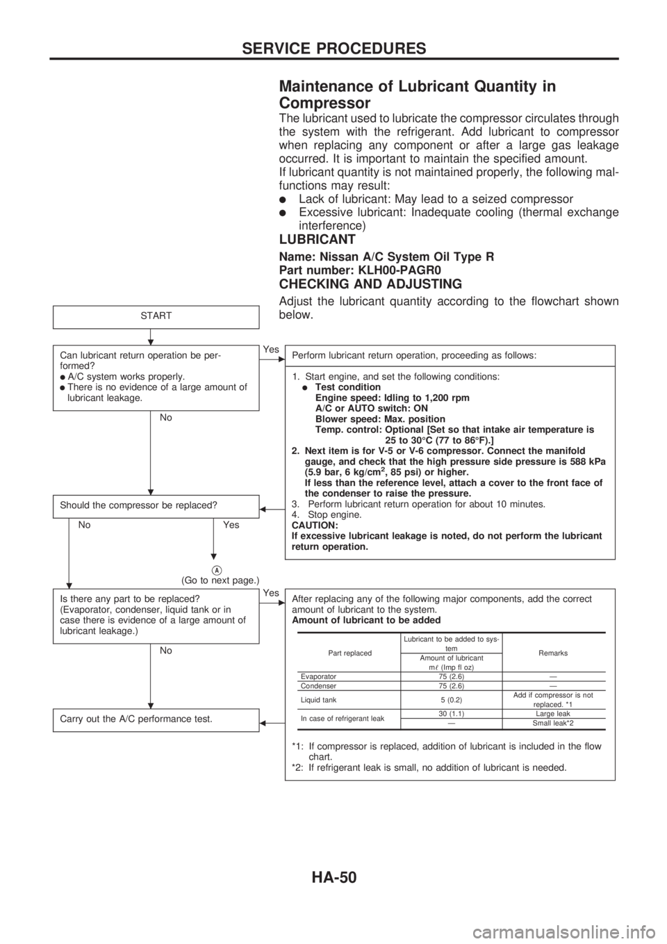
Adjust the lubricant quantity according to the flowchart shown
below.
START
Can lubricant return operation be per-
formed?
lA/C system works properly.lThere is no evidence of a large amount of
lubricant leakage.
No
cYes
Perform lubricant return operation, proceeding as follows:
-----------------------------------------------------------------------------------------------------------------------------------------------------------------------------------------------------------------------------------------------------------------------------------------------------------------------------------------------------------------------------------------------------------------------------------------------------------------------------------------------------------------------------------
1. Start engine, and set the following conditions:
lTest condition
Engine speed: Idling to 1,200 rpm
A/C or AUTO switch: ON
Blower speed: Max. position
Temp. control: Optional [Set so that intake air temperature is
25 to 30ÉC (77 to 86ÉF).]
2. Next item is for V-5 or V-6 compressor. Connect the manifold
gauge, and check that the high pressure side pressure is 588 kPa
(5.9 bar, 6 kg/cm
2, 85 psi) or higher.
If less than the reference level, attach a cover to the front face of
the condenser to raise the pressure.
3. Perform lubricant return operation for about 10 minutes.
4. Stop engine.
CAUTION:
If excessive lubricant leakage is noted, do not perform the lubricant
return operation.
Should the compressor be replaced?
No Yes
b
VA(Go to next page.)
Is there any part to be replaced?
(Evaporator, condenser, liquid tank or in
case there is evidence of a large amount of
lubricant leakage.)
No
cYes
After replacing any of the following major components, add the correct
amount of lubricant to the system.
Amount of lubricant to be added
*1: If compressor is replaced, addition of lubricant is included in the flow
chart.
*2: If refrigerant leak is small, no addition of lubricant is needed.
Carry out the A/C performance test.b
Part replacedLubricant to be added to sys-
tem
Remarks
Amount of lubricant
m!(Imp fl oz)
Evaporator 75 (2.6) Ð
Condenser 75 (2.6) Ð
Liquid tank 5 (0.2)Add if compressor is not
replaced. *1
In case of refrigerant leak30 (1.1) Large leak
Ð Small leak*2
.
.
.
.
.
SERVICE PROCEDURES
HA-50
Page 923 of 1659
Refrigerant Lines
lRefer to page HA-2 regarding ``Precautions for Refrigerant
Connection''.
RHD MODELS WITH DIESEL ENGINE
RHA352G
SERVICE PROCEDURES
HA-52
Page 924 of 1659
lRefer to page HA-2 regarding ``Precautions for Refrigerant
Connection''.
RHD MODELS WITH KA24 ENGINE
RHA353G
SERVICE PROCEDURES
Refrigerant Lines (Cont'd)
HA-53
Page 925 of 1659
lRefer to page HA-2 regarding ``Precautions for Refrigerant
Connection''.
LHD MODELS WITH DIESEL ENGINE
RHA372GA
.
SERVICE PROCEDURES
Refrigerant Lines (Cont'd)
HA-54
Page 926 of 1659
lRefer to page HA-2 regarding ``Precautions for Refrigerant
Connection''.
LHD MODELS WITH GASOLINE ENGINE
RHA356GA
.
SERVICE PROCEDURES
Refrigerant Lines (Cont'd)
HA-55