Page 959 of 1659

Cooling System Inspection
WARNING:
Never remove the radiator cap when the engine is hot; seri-
ous burns could be caused by high pressure fluid escaping
from the radiator.
Wrap a thick cloth around cap and carefully loosen it a quar-
ter turn to release built-up pressure. Then remove the cap
completely.
CHECKING HOSES
Check hoses for proper attachment, leaks, cracks, damage,
loose connections, chafing and deterioration.
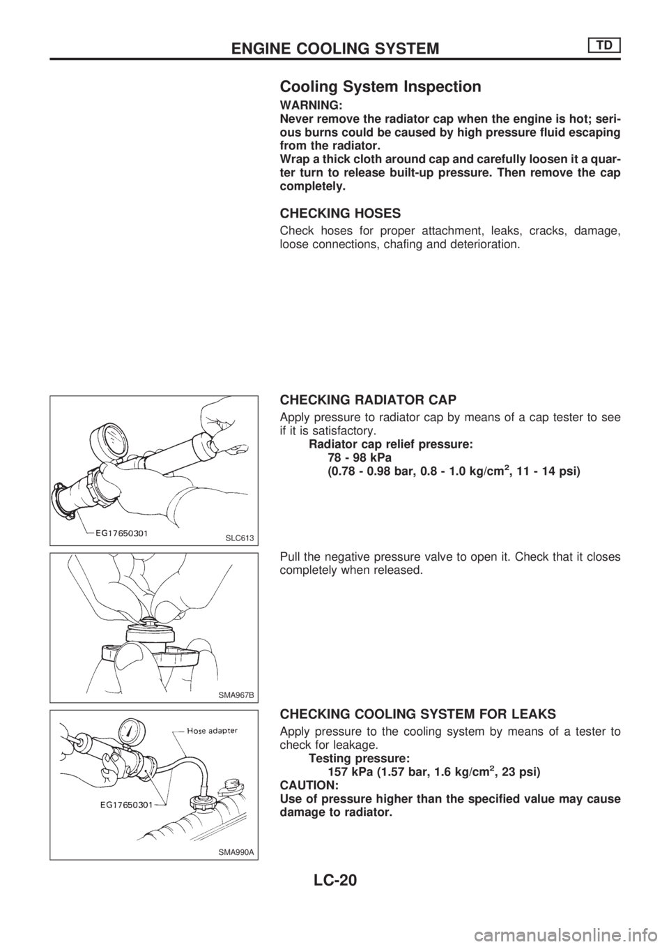
CHECKING RADIATOR CAP
Apply pressure to radiator cap by means of a cap tester to see
if it is satisfactory.
Radiator cap relief pressure:
78-98kPa
(0.78 - 0.98 bar, 0.8 - 1.0 kg/cm
2, 11 - 14 psi)
Pull the negative pressure valve to open it. Check that it closes
completely when released.
CHECKING COOLING SYSTEM FOR LEAKS
Apply pressure to the cooling system by means of a tester to
check for leakage.
Testing pressure:
157 kPa (1.57 bar, 1.6 kg/cm
2, 23 psi)
CAUTION:
Use of pressure higher than the specified value may cause
damage to radiator.
SLC613
SMA967B
SMA990A
ENGINE COOLING SYSTEMTD
LC-20
Page 960 of 1659
Water Pump and Cooling Fan (Camshaft
driven)
REMOVAL AND INSTALLATION
Drain coolant from drain plugs on cylinder block and radiator.
Cylinder block drain plug
(Use proper sealant):
:20-29Nzm (2.0 - 3.0 kg-m, 14 - 22 ft-lb)
CAUTION:
lWhen removing water pump assembly, be careful not to
get coolant on drive belt.
lWater pump cannot be disassembled and should be
replaced as a unit.
lAlways replace with new gasket.
lAfter assembly, verify the fan does not wobble or flap
while the engine is running.
lAfter installing water pump, connect hose and clamp
securely, then check for leaks using radiator cap tester.
WARNING:
When the engine is running, keep hands and clothing away
from moving parts such as drive belts and fan.
SMA617C
SLC978-A
ENGINE COOLING SYSTEMTD
LC-21
Page 961 of 1659
INSPECTION
1. Check for badly rusted or corroded body assembly and vane.
2. Check for rough operation due to excessive end play.
3. Check fan coupling for rough operation, wobbling, oil leakage
or bent bimetal.
The water pump and fan coupling cannot be disassembled
and should be replaced as a unit.
SLC979
SLC244
SLC245
ENGINE COOLING SYSTEMTD
Water Pump and Cooling Fan (Camshaft
driven) (Cont'd)
LC-22
Page 962 of 1659
Thermostat
lAfter installation, run engine for a few minutes, and
check for leaks.
lBe careful not to spill coolant over engine compartment.
Place a rag to absorb coolant.
INSPECTION
1. Check for valve seating condition at ordinary temperatures.
It should seat tightly.
2. Check valve opening temperature and valve lift.
Tropical type Standard type
Valve opening tempera-
ture ÉC (ÉF)76.5 (170) 82 (180)
Valve lift mm/ÉC (in/ÉF)More than 8/90
(0.31/194)More than 8/95
(0.31/203)
3. Then check if valve closes at 5ÉC (9ÉF) below valve opening
temperature.
DLC007
SLC343
ENGINE COOLING SYSTEMTD
LC-23
Page 963 of 1659
Radiator
REMOVAL AND INSTALLATION
1. Remove under cover.
2. Drain coolant from radiator drain plug.
3. Disconnect radiator upper and lower hoses.
4. Remove radiator lower shroud.
5. Disconnect reservoir tank hose.
6. Remove radiator.
7. After repairing or replacing radiator, install any part removed
in reverse order of removal.
Refilling Engine Coolant
For details on refilling engine coolant, refer to MA section
(``REFILLING ENGINE COOLANT'', ``Changing Engine Cool-
ant'').
DLC008
ENGINE COOLING SYSTEMTD
LC-24
Page 964 of 1659
Wiring Diagram
HLC005
ENGINE ROOM FAN MOTOR ELECTRICAL CIRCUITTD
LC-25
Page 965 of 1659
Cooling Fan (Motor driven)
Electrical Components Inspection
COOLING FAN MOTOR
1. Disconnect cooling fan motor harness connector.
2. Supply cooling fan motor terminals with battery voltage and
check operation.
Cooling fan motor should operate.
If NG, replace cooling fan motor.
COOLING FAN RELAY
DLC009
DLC010
SLC143B
DLC011
ENGINE ROOM FAN MOTOR ELECTRICAL CIRCUITTD
LC-26
Page 966 of 1659
Check continuity between terminalsV3andV4.
Conditions Continuity
12V direct current supply between
terminals
V1andV2Yes
No current supply No
If NG, replace relay.
THERMOSWITCH
1. Disconnect thermoswitch harness connector.
2. Check operation as shown in the figure.
Coolant temperature
ÉC (ÉF)Operation Continuity
Increased to 92 - 98
(198 - 208)OFF®ON ON: Exists.
Decreased to 87 - 93
(189 - 199)ON®OFF OFF: Does not exist.
TRIPLE-PRESSURE SWITCH
For inspection of this switch, refer to HA section (``TRIPLE-
PRESSURE SWITCH'', ``Electrical Components Inspection'').
SEF440N
DLC012
SEF643Q
ENGINE ROOM FAN MOTOR ELECTRICAL CIRCUITTD
Electrical Components Inspection (Cont'd)
LC-27