Page 879 of 1659
HFC-134a (R-134a) Service Tools and
Equipment
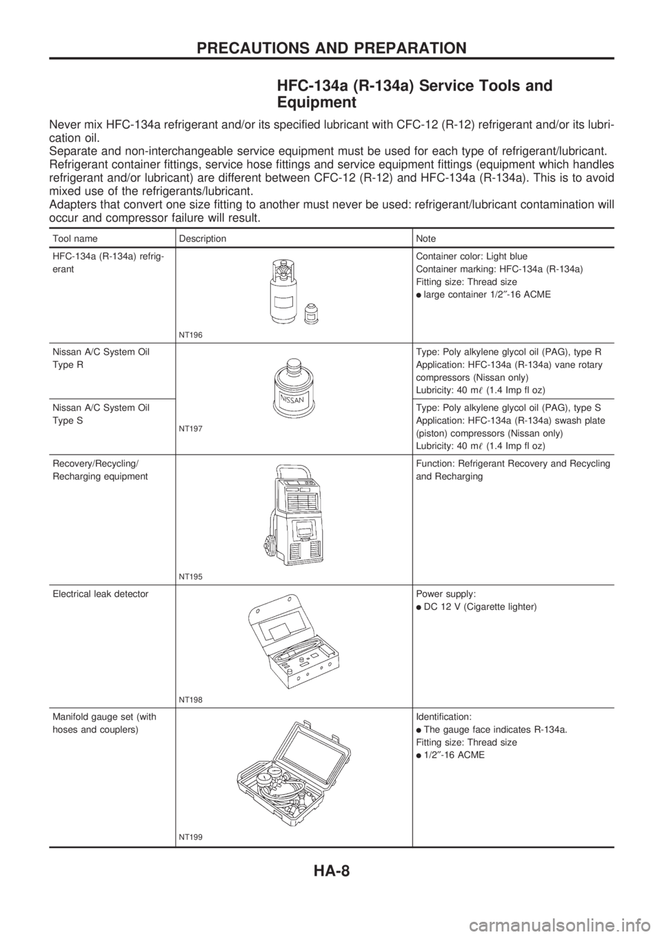
Never mix HFC-134a refrigerant and/or its specified lubricant with CFC-12 (R-12) refrigerant and/or its lubri-
cation oil.
Separate and non-interchangeable service equipment must be used for each type of refrigerant/lubricant.
Refrigerant container fittings, service hose fittings and service equipment fittings (equipment which handles
refrigerant and/or lubricant) are different between CFC-12 (R-12) and HFC-134a (R-134a). This is to avoid
mixed use of the refrigerants/lubricant.
Adapters that convert one size fitting to another must never be used: refrigerant/lubricant contamination will
occur and compressor failure will result.
Tool name Description Note
HFC-134a (R-134a) refrig-
erant
NT196
Container color: Light blue
Container marking: HFC-134a (R-134a)
Fitting size: Thread size
llarge container 1/2²-16 ACME
Nissan A/C System Oil
Type R
NT197
Type: Poly alkylene glycol oil (PAG), type R
Application: HFC-134a (R-134a) vane rotary
compressors (Nissan only)
Lubricity: 40 m!(1.4 Imp fl oz)
Nissan A/C System Oil
Type SType: Poly alkylene glycol oil (PAG), type S
Application: HFC-134a (R-134a) swash plate
(piston) compressors (Nissan only)
Lubricity: 40 m!(1.4 Imp fl oz)
Recovery/Recycling/
Recharging equipment
NT195
Function: Refrigerant Recovery and Recycling
and Recharging
Electrical leak detector
NT198
Power supply:
lDC 12 V (Cigarette lighter)
Manifold gauge set (with
hoses and couplers)
NT199
Identification:
lThe gauge face indicates R-134a.
Fitting size: Thread size
l1/2²-16 ACME
PRECAUTIONS AND PREPARATION
HA-8
Page 882 of 1659
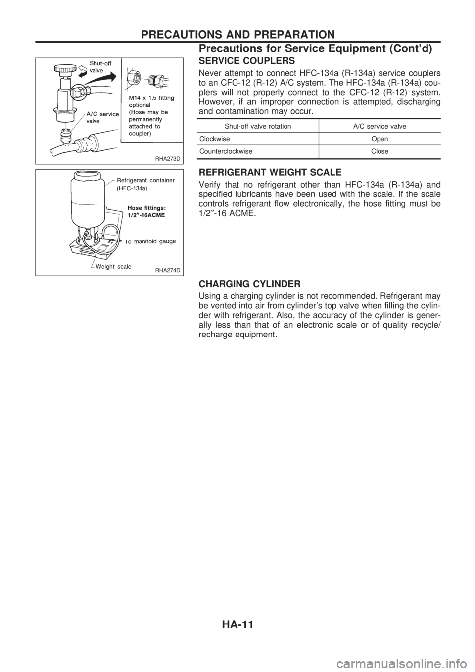
SERVICE COUPLERS
Never attempt to connect HFC-134a (R-134a) service couplers
to an CFC-12 (R-12) A/C system. The HFC-134a (R-134a) cou-
plers will not properly connect to the CFC-12 (R-12) system.
However, if an improper connection is attempted, discharging
and contamination may occur.
Shut-off valve rotation A/C service valve
Clockwise Open
Counterclockwise Close
REFRIGERANT WEIGHT SCALE
Verify that no refrigerant other than HFC-134a (R-134a) and
specified lubricants have been used with the scale. If the scale
controls refrigerant flow electronically, the hose fitting must be
1/2²-16 ACME.
CHARGING CYLINDER
Using a charging cylinder is not recommended. Refrigerant may
be vented into air from cylinder's top valve when filling the cylin-
der with refrigerant. Also, the accuracy of the cylinder is gener-
ally less than that of an electronic scale or of quality recycle/
recharge equipment.
RHA273D
RHA274D
PRECAUTIONS AND PREPARATION
Precautions for Service Equipment (Cont'd)
HA-11
Page 883 of 1659
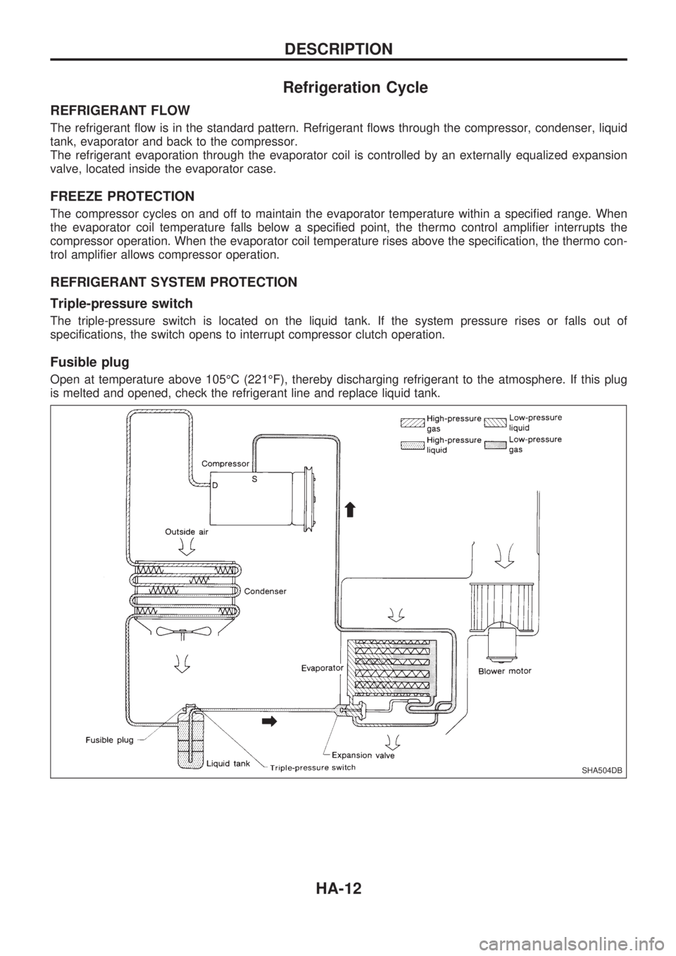
Refrigeration Cycle
REFRIGERANT FLOW
The refrigerant flow is in the standard pattern. Refrigerant flows through the compressor, condenser, liquid
tank, evaporator and back to the compressor.
The refrigerant evaporation through the evaporator coil is controlled by an externally equalized expansion
valve, located inside the evaporator case.
FREEZE PROTECTION
The compressor cycles on and off to maintain the evaporator temperature within a specified range. When
the evaporator coil temperature falls below a specified point, the thermo control amplifier interrupts the
compressor operation. When the evaporator coil temperature rises above the specification, the thermo con-
trol amplifier allows compressor operation.
REFRIGERANT SYSTEM PROTECTION
Triple-pressure switch
The triple-pressure switch is located on the liquid tank. If the system pressure rises or falls out of
specifications, the switch opens to interrupt compressor clutch operation.
Fusible plug
Open at temperature above 105ÉC (221ÉF), thereby discharging refrigerant to the atmosphere. If this plug
is melted and opened, check the refrigerant line and replace liquid tank.
SHA504DB
DESCRIPTION
HA-12
Page 919 of 1659
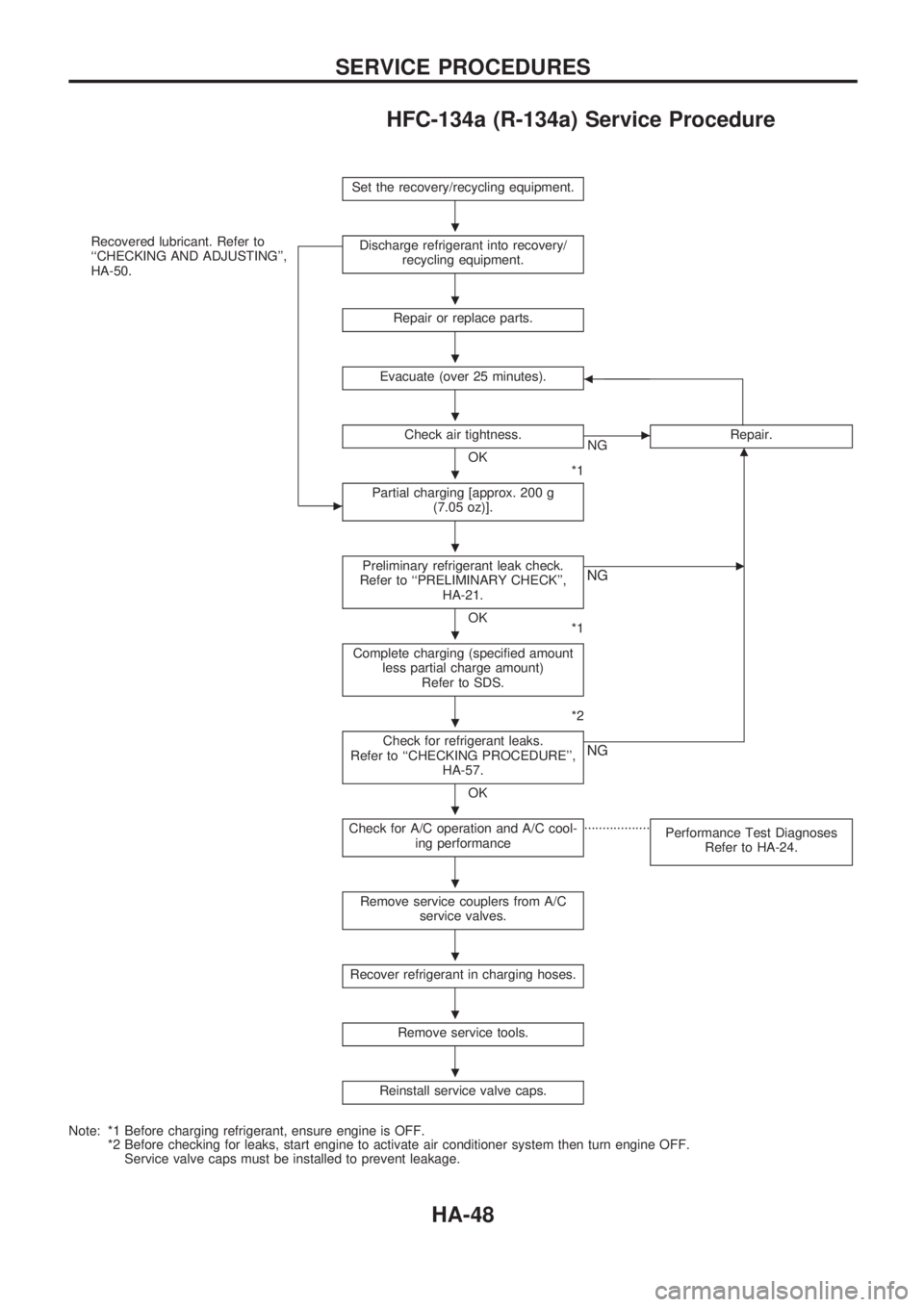
HFC-134a (R-134a) Service Procedure
Set the recovery/recycling equipment.
Recovered lubricant. Refer to
``CHECKING AND ADJUSTING'',
HA-50.
c
Discharge refrigerant into recovery/
recycling equipment.
Repair or replace parts.
Evacuate (over 25 minutes).b
Check air tightness.
OK
*1
cNGRepair.m
Partial charging [approx. 200 g
(7.05 oz)].
Preliminary refrigerant leak check.
Refer to ``PRELIMINARY CHECK'',
HA-21.
OK
*1
cNG
Complete charging (specified amount
less partial charge amount)
Refer to SDS.
*2
Check for refrigerant leaks.
Refer to ``CHECKING PROCEDURE'',
HA-57.
OK
NG
Check for A/C operation and A/C cool-
ing performance..................
Performance Test Diagnoses
Refer to HA-24.
Remove service couplers from A/C
service valves.
Recover refrigerant in charging hoses.
Remove service tools.
Reinstall service valve caps.
Note: *1 Before charging refrigerant, ensure engine is OFF.
*2 Before checking for leaks, start engine to activate air conditioner system then turn engine OFF.
Service valve caps must be installed to prevent leakage.
.
.
.
.
.
.
.
.
.
.
.
.
.
SERVICE PROCEDURES
HA-48
Page 920 of 1659
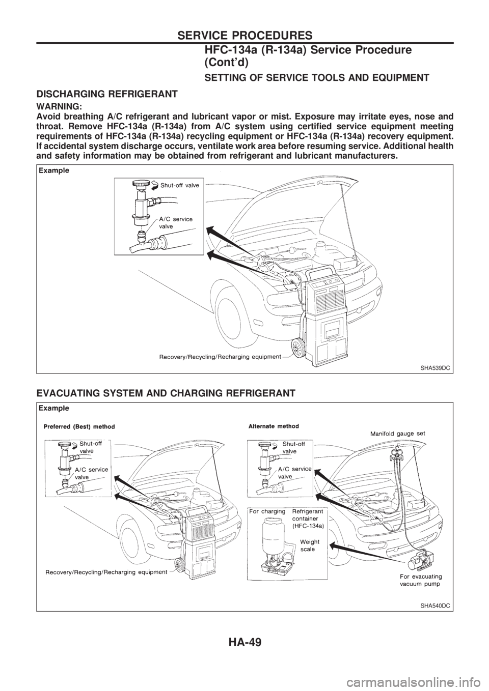
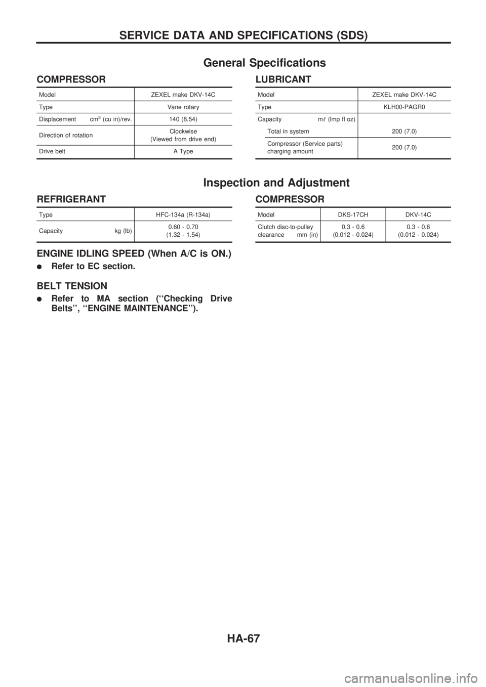
SETTING OF SERVICE TOOLS AND EQUIPMENT
DISCHARGING REFRIGERANT
WARNING:
Avoid breathing A/C refrigerant and lubricant vapor or mist. Exposure may irritate eyes, nose and
throat. Remove HFC-134a (R-134a) from A/C system using certified service equipment meeting
requirements of HFC-134a (R-134a) recycling equipment or HFC-134a (R-134a) recovery equipment.
If accidental system discharge occurs, ventilate work area before resuming service. Additional health
and safety information may be obtained from refrigerant and lubricant manufacturers.
EVACUATING SYSTEM AND CHARGING REFRIGERANT
SHA539DC
SHA540DC
SERVICE PROCEDURES
HFC-134a (R-134a) Service Procedure
(Cont'd)
HA-49
Page 922 of 1659
VA
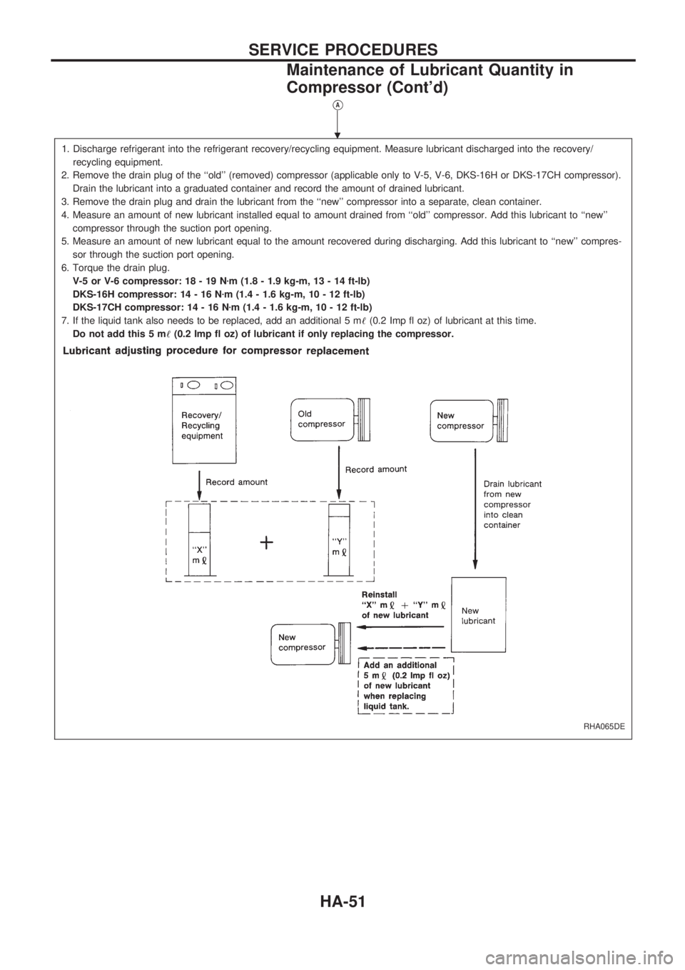
1. Discharge refrigerant into the refrigerant recovery/recycling equipment. Measure lubricant discharged into the recovery/
recycling equipment.
2. Remove the drain plug of the ``old'' (removed) compressor (applicable only to V-5, V-6, DKS-16H or DKS-17CH compressor).
Drain the lubricant into a graduated container and record the amount of drained lubricant.
3. Remove the drain plug and drain the lubricant from the ``new'' compressor into a separate, clean container.
4. Measure an amount of new lubricant installed equal to amount drained from ``old'' compressor. Add this lubricant to ``new''
compressor through the suction port opening.
5. Measure an amount of new lubricant equal to the amount recovered during discharging. Add this lubricant to ``new'' compres-
sor through the suction port opening.
6. Torque the drain plug.
V-5 or V-6 compressor: 18 - 19 Nzm (1.8 - 1.9 kg-m, 13 - 14 ft-lb)
DKS-16H compressor: 14 - 16 Nzm (1.4 - 1.6 kg-m, 10 - 12 ft-lb)
DKS-17CH compressor: 14 - 16 Nzm (1.4 - 1.6 kg-m, 10 - 12 ft-lb)
7. If the liquid tank also needs to be replaced, add an additional 5 m!(0.2 Imp fl oz) of lubricant at this time.
Do not add this 5 m!(0.2 Imp fl oz) of lubricant if only replacing the compressor.
RHA065DE
.
SERVICE PROCEDURES
Maintenance of Lubricant Quantity in
Compressor (Cont'd)
HA-51
Page 938 of 1659
General Specifications
COMPRESSOR
Model ZEXEL make DKV-14C
Type Vane rotary
Displacement cm
3(cu in)/rev. 140 (8.54)
Direction of rotationClockwise
(Viewed from drive end)
Drive belt A Type
LUBRICANT
Model ZEXEL make DKV-14C
Type KLH00-PAGR0
Capacity m!(lmp fl oz)
Total in system 200 (7.0)
Compressor (Service parts)
charging amount200 (7.0)
Inspection and Adjustment
REFRIGERANT
Type HFC-134a (R-134a)
Capacity kg (lb)0.60 - 0.70
(1.32 - 1.54)
ENGINE IDLING SPEED (When A/C is ON.)
lRefer to EC section.
BELT TENSION
lRefer to MA section (``Checking Drive
Belts'', ``ENGINE MAINTENANCE'').
COMPRESSOR
Model DKS-17CH DKV-14C
Clutch disc-to-pulley
clearance mm (in)0.3 - 0.6
(0.012 - 0.024)0.3 - 0.6
(0.012 - 0.024)
SERVICE DATA AND SPECIFICATIONS (SDS)
HA-67
Page 1199 of 1659
![NISSAN PICK-UP 1998 Repair Manual INTERMITTENT PROBLEM DIAGNOSTIC CODE CHART (``SELF-DIAG [PAST] or
``TROUBLE DIAG RECORD)
Diagnostic item Explanation Repair order
NO SELF DIAGNOSTIC
FAILURE INDICATED.
lNo malfunction is detected.](/manual-img/5/57374/w960_57374-1198.png "NISSAN PICK-UP 1998 Repair Manual INTERMITTENT PROBLEM DIAGNOSTIC CODE CHART (``SELF-DIAG [PAST] or
``TROUBLE DIAG RECORD)
Diagnostic item Explanation Repair order
NO SELF DIAGNOSTIC
FAILURE INDICATED.
lNo malfunction is detected.")
INTERMITTENT PROBLEM DIAGNOSTIC CODE CHART (``SELF-DIAG [PAST]'' or
``TROUBLE DIAG RECORD'')
Diagnostic item Explanation Repair order
NO SELF DIAGNOSTIC
FAILURE INDICATED.
lNo malfunction is detected.lGo to DIAGNOSTIC PROCEDURE 3 (RS-31)
after charging battery.
AIRBAG MODULE
[OPEN]
lDriver's air bag module circuit is open.
(including the spiral cable)lVisually check the wiring harness connection.
lReplace the harness if it has visible damage.
lReplace driver's air bag module.
(Before disposal of it, it must be deployed.)
lReplace the spiral cable.
lReplace the diagnosis sensor unit. AIRBAG MODULE
[VB-SHORT]
lDriver's air bag module circuit is shorted to
some power supply circuit. (including the spi-
ral cable)
AIRBAG MODULE
[GND-SHORT]
lDriver's air bag module circuit is shorted to
ground. (including the spiral cable)
AIRBAG MODULE
[SHORT]
lDriver's air bag module circuits are shorted to
each other.
CONTROL UNIT
lDiagnosis sensor unit is out of order.lVisually check the wiring harness connection.
lReplace the diagnosis sensor unit.
* Intermittent problem areas cannot be easily located. For this reason, perform the procedures outlined under the repair order, then
make the final system check.
TROUBLE DIAGNOSES Ð Supplemental Restraint System (SRS) Ð
4WD models
Trouble Diagnoses with CONSULT (Cont'd)
RS-36