1998 NISSAN PICK-UP relay
[x] Cancel search: relayPage 203 of 1659
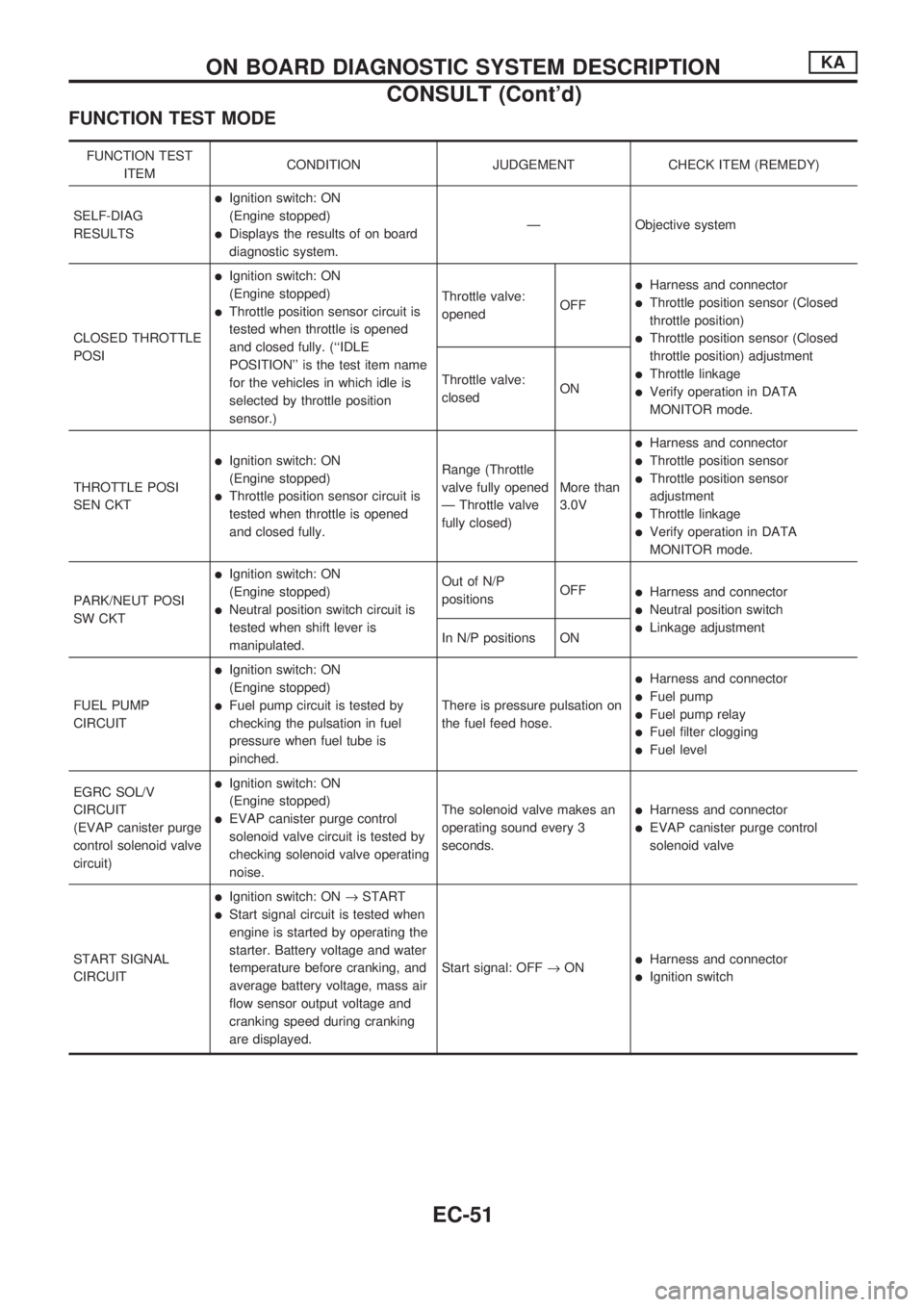
FUNCTION TEST MODE
FUNCTION TEST
ITEMCONDITION JUDGEMENT CHECK ITEM (REMEDY)
SELF-DIAG
RESULTS
lIgnition switch: ON
(Engine stopped)
lDisplays the results of on board
diagnostic system.Ð Objective system
CLOSED THROTTLE
POSI
lIgnition switch: ON
(Engine stopped)
lThrottle position sensor circuit is
tested when throttle is opened
and closed fully. (``IDLE
POSITION'' is the test item name
for the vehicles in which idle is
selected by throttle position
sensor.)Throttle valve:
openedOFF
lHarness and connector
lThrottle position sensor (Closed
throttle position)
lThrottle position sensor (Closed
throttle position) adjustment
lThrottle linkage
lVerify operation in DATA
MONITOR mode. Throttle valve:
closedON
THROTTLE POSI
SEN CKT
lIgnition switch: ON
(Engine stopped)
lThrottle position sensor circuit is
tested when throttle is opened
and closed fully.Range (Throttle
valve fully opened
Ð Throttle valve
fully closed)More than
3.0V
lHarness and connector
lThrottle position sensor
lThrottle position sensor
adjustment
lThrottle linkage
lVerify operation in DATA
MONITOR mode.
PARK/NEUT POSI
SW CKT
lIgnition switch: ON
(Engine stopped)
lNeutral position switch circuit is
tested when shift lever is
manipulated.Out of N/P
positionsOFF
lHarness and connector
lNeutral position switch
lLinkage adjustment
In N/P positions ON
FUEL PUMP
CIRCUIT
lIgnition switch: ON
(Engine stopped)
lFuel pump circuit is tested by
checking the pulsation in fuel
pressure when fuel tube is
pinched.There is pressure pulsation on
the fuel feed hose.
lHarness and connector
lFuel pump
lFuel pump relay
lFuel filter clogging
lFuel level
EGRC SOL/V
CIRCUIT
(EVAP canister purge
control solenoid valve
circuit)
lIgnition switch: ON
(Engine stopped)
lEVAP canister purge control
solenoid valve circuit is tested by
checking solenoid valve operating
noise.The solenoid valve makes an
operating sound every 3
seconds.lHarness and connector
lEVAP canister purge control
solenoid valve
START SIGNAL
CIRCUIT
lIgnition switch: ON®START
lStart signal circuit is tested when
engine is started by operating the
starter. Battery voltage and water
temperature before cranking, and
average battery voltage, mass air
flow sensor output voltage and
cranking speed during cranking
are displayed.Start signal: OFF®ON
lHarness and connector
lIgnition switch
ON BOARD DIAGNOSTIC SYSTEM DESCRIPTIONKA
CONSULT (Cont'd)
EC-51
Page 213 of 1659
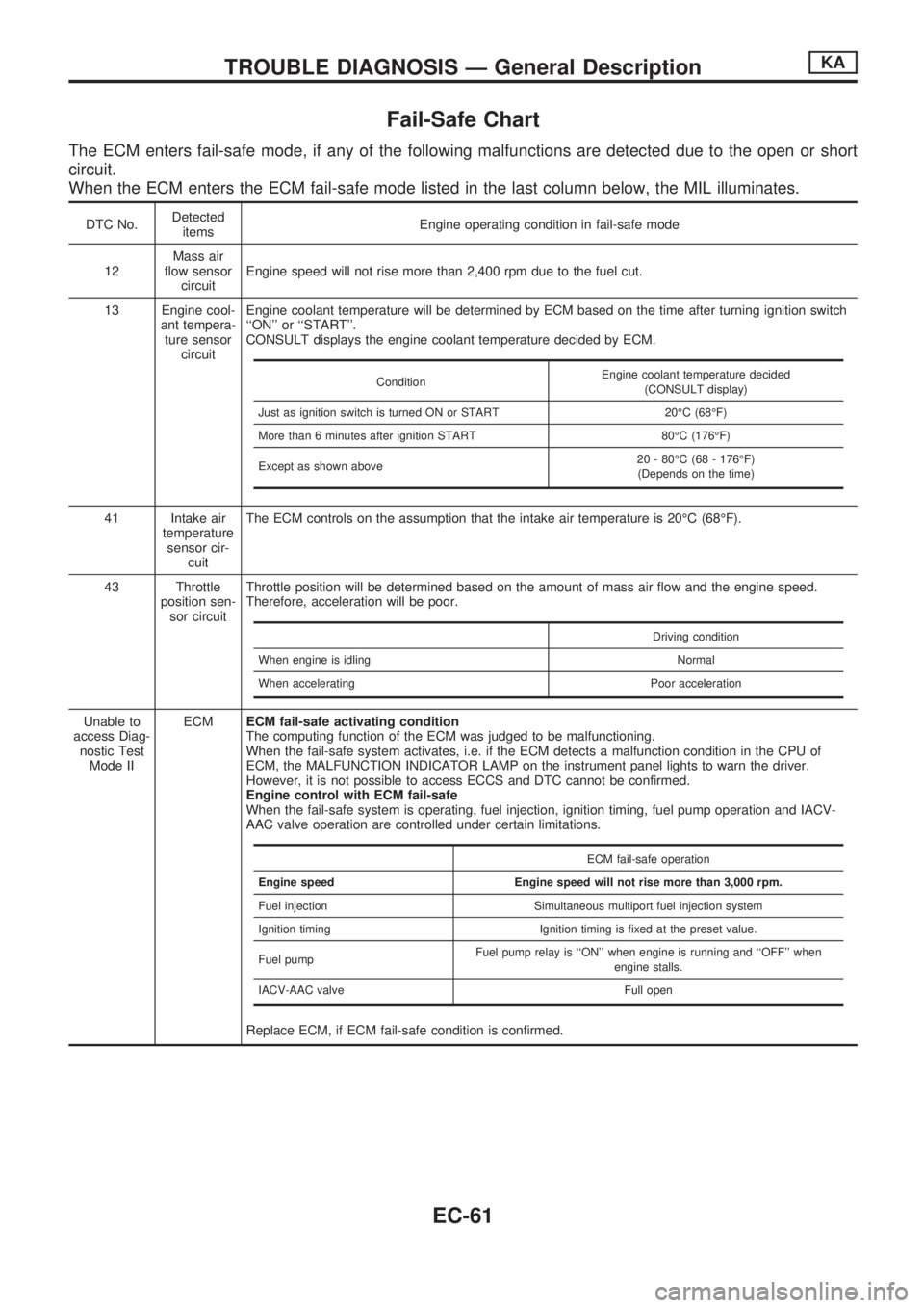
Fail-Safe Chart
The ECM enters fail-safe mode, if any of the following malfunctions are detected due to the open or short
circuit.
When the ECM enters the ECM fail-safe mode listed in the last column below, the MIL illuminates.
DTC No.Detected
itemsEngine operating condition in fail-safe mode
12Mass air
flow sensor
circuitEngine speed will not rise more than 2,400 rpm due to the fuel cut.
13 Engine cool-
ant tempera-
ture sensor
circuitEngine coolant temperature will be determined by ECM based on the time after turning ignition switch
``ON'' or ``START''.
CONSULT displays the engine coolant temperature decided by ECM.
41 Intake air
temperature
sensor cir-
cuitThe ECM controls on the assumption that the intake air temperature is 20ÉC (68ÉF).
43 Throttle
position sen-
sor circuitThrottle position will be determined based on the amount of mass air flow and the engine speed.
Therefore, acceleration will be poor.
Unable to
access Diag-
nostic Test
Mode IIECMECM fail-safe activating condition
The computing function of the ECM was judged to be malfunctioning.
When the fail-safe system activates, i.e. if the ECM detects a malfunction condition in the CPU of
ECM, the MALFUNCTION INDICATOR LAMP on the instrument panel lights to warn the driver.
However, it is not possible to access ECCS and DTC cannot be confirmed.
Engine control with ECM fail-safe
When the fail-safe system is operating, fuel injection, ignition timing, fuel pump operation and IACV-
AAC valve operation are controlled under certain limitations.
Replace ECM, if ECM fail-safe condition is confirmed.
ConditionEngine coolant temperature decided
(CONSULT display)
Just as ignition switch is turned ON or START 20ÉC (68ÉF)
More than 6 minutes after ignition START 80ÉC (176ÉF)
Except as shown above20 - 80ÉC (68 - 176ÉF)
(Depends on the time)
Driving condition
When engine is idling Normal
When accelerating Poor acceleration
ECM fail-safe operation
Engine speed Engine speed will not rise more than 3,000 rpm.
Fuel injection Simultaneous multiport fuel injection system
Ignition timing Ignition timing is fixed at the preset value.
Fuel pumpFuel pump relay is ``ON'' when engine is running and ``OFF'' when
engine stalls.
IACV-AAC valve Full open
TROUBLE DIAGNOSIS Ð General DescriptionKA
EC-61
Page 222 of 1659
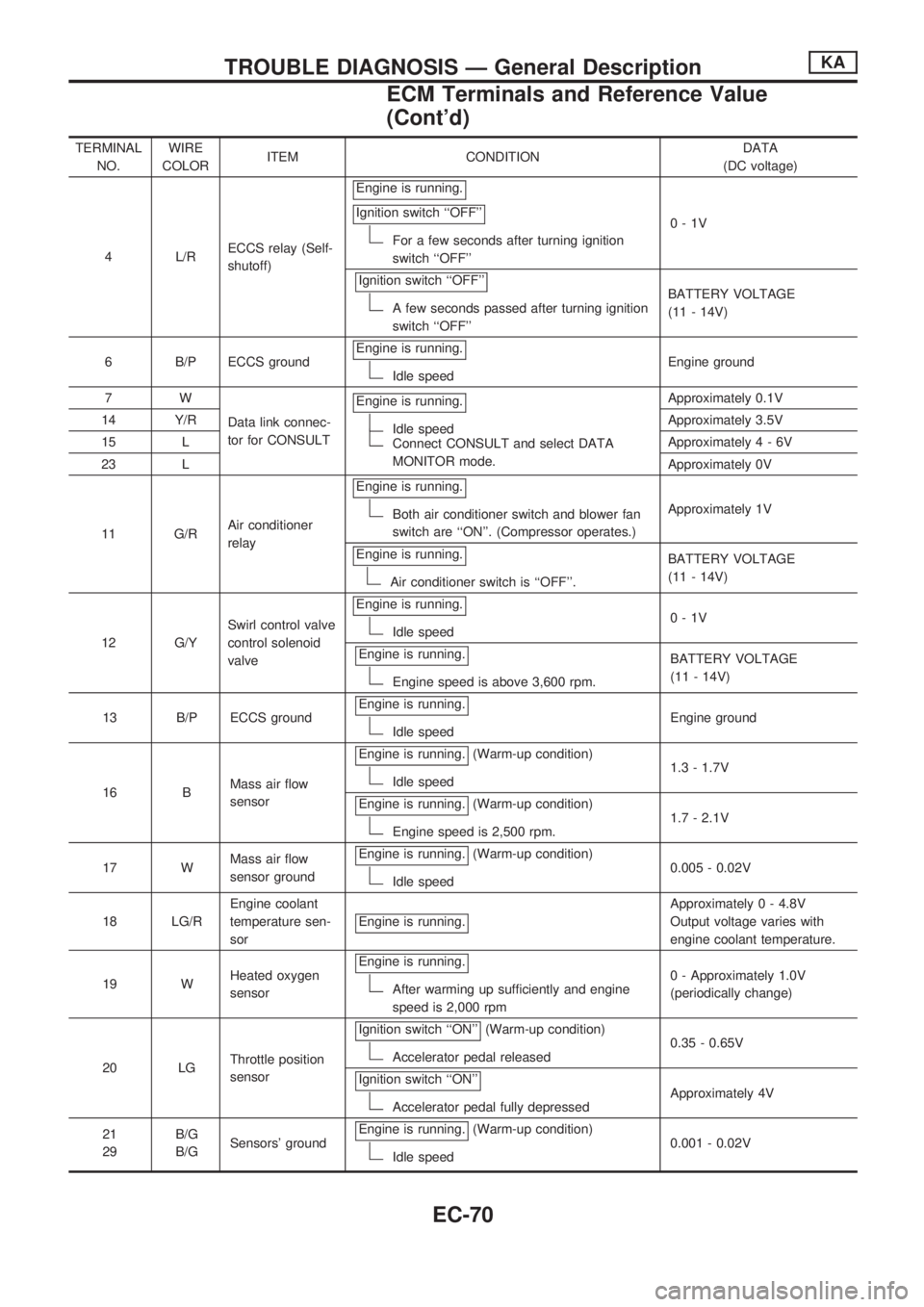
TERMINAL
NO.WIRE
COLORITEM CONDITIONDATA
(DC voltage)
4 L/RECCS relay (Self-
shutoff)Engine is running.
Ignition switch ``OFF''
For a few seconds after turning ignition
switch ``OFF''0-1V
Ignition switch ``OFF''
A few seconds passed after turning ignition
switch ``OFF''BATTERY VOLTAGE
(11 - 14V)
6 B/P ECCS groundEngine is running.
Idle speedEngine ground
7W
Data link connec-
tor for CONSULTEngine is running.
Idle speedConnect CONSULT and select DATA
MONITOR mode.Approximately 0.1V
14 Y/RApproximately 3.5V
15 LApproximately4-6V
23 LApproximately 0V
11 G/RAir conditioner
relayEngine is running.
Both air conditioner switch and blower fan
switch are ``ON''. (Compressor operates.)Approximately 1V
Engine is running.
Air conditioner switch is ``OFF''.BATTERY VOLTAGE
(11 - 14V)
12 G/YSwirl control valve
control solenoid
valveEngine is running.
Idle speed0-1V
Engine is running.
Engine speed is above 3,600 rpm.BATTERY VOLTAGE
(11 - 14V)
13 B/P ECCS groundEngine is running.
Idle speedEngine ground
16 BMass air flow
sensorEngine is running.
(Warm-up condition)
Idle speed1.3 - 1.7V
Engine is running.
(Warm-up condition)
Engine speed is 2,500 rpm.1.7 - 2.1V
17 WMass air flow
sensor groundEngine is running.
(Warm-up condition)
Idle speed0.005 - 0.02V
18 LG/REngine coolant
temperature sen-
sorEngine is running.
Approximately 0 - 4.8V
Output voltage varies with
engine coolant temperature.
19 WHeated oxygen
sensorEngine is running.
After warming up sufficiently and engine
speed is 2,000 rpm0 - Approximately 1.0V
(periodically change)
20 LGThrottle position
sensorIgnition switch ``ON''
(Warm-up condition)
Accelerator pedal released0.35 - 0.65V
Ignition switch ``ON''
Accelerator pedal fully depressedApproximately 4V
21
29B/G
B/GSensors' groundEngine is running.
(Warm-up condition)
Idle speed0.001 - 0.02V
TROUBLE DIAGNOSIS Ð General DescriptionKA
ECM Terminals and Reference Value
(Cont'd)
EC-70
Page 225 of 1659
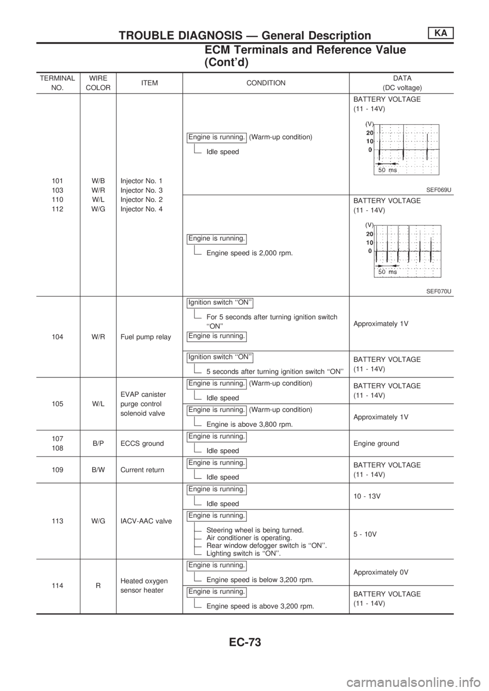
TERMINAL
NO.WIRE
COLORITEM CONDITIONDATA
(DC voltage)
101
103
110
112W/B
W/R
W/L
W/GInjector No. 1
Injector No. 3
Injector No. 2
Injector No. 4Engine is running.
(Warm-up condition)
Idle speedBATTERY VOLTAGE
(11 - 14V)
SEF069U
Engine is running.
Engine speed is 2,000 rpm.BATTERY VOLTAGE
(11 - 14V)
SEF070U
104 W/R Fuel pump relayIgnition switch ``ON''
For 5 seconds after turning ignition switch
``ON''
Engine is running.Approximately 1V
Ignition switch ``ON''
5 seconds after turning ignition switch ``ON''BATTERY VOLTAGE
(11 - 14V)
105 W/LEVAP canister
purge control
solenoid valveEngine is running.
(Warm-up condition)
Idle speedBATTERY VOLTAGE
(11 - 14V)
Engine is running.
(Warm-up condition)
Engine is above 3,800 rpm.Approximately 1V
107
108B/P ECCS groundEngine is running.
Idle speedEngine ground
109 B/W Current returnEngine is running.
Idle speedBATTERY VOLTAGE
(11 - 14V)
113 W/G IACV-AAC valveEngine is running.
Idle speed10 - 13V
Engine is running.
Steering wheel is being turned.Air conditioner is operating.Rear window defogger switch is ``ON''.Lighting switch is ``ON''.5 - 10V
114 RHeated oxygen
sensor heaterEngine is running.
Engine speed is below 3,200 rpm.Approximately 0V
Engine is running.
Engine speed is above 3,200 rpm.BATTERY VOLTAGE
(11 - 14V)
TROUBLE DIAGNOSIS Ð General DescriptionKA
ECM Terminals and Reference Value
(Cont'd)
EC-73
Page 227 of 1659
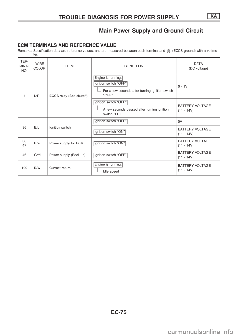
Main Power Supply and Ground Circuit
ECM TERMINALS AND REFERENCE VALUE
Remarks: Specification data are reference values, and are measured between each terminal andV39(ECCS ground) with a voltme-
ter.
TER-
MINAL
NO.WIRE
COLORITEM CONDITIONDATA
(DC voltage)
4 L/R ECCS relay (Self-shutoff)Engine is running.
Ignition switch ``OFF''
For a few seconds after turning ignition switch
``OFF''0-1V
Ignition switch ``OFF''
A few seconds passed after turning ignition
switch ``OFF''BATTERY VOLTAGE
(11 - 14V)
36 B/L Ignition switchIgnition switch ``OFF''
0V
Ignition switch ``ON''
BATTERY VOLTAGE
(11 - 14V)
38
47B/W Power supply for ECM Ignition switch ``ON''
BATTERY VOLTAGE
(11 - 14V)
46 GY/L Power supply (Back-up) Ignition switch ``OFF''
BATTERY VOLTAGE
(11 - 14V)
109 B/W Current returnEngine is running.
Idle speedBATTERY VOLTAGE
(11 - 14V)
TROUBLE DIAGNOSIS FOR POWER SUPPLYKA
EC-75
Page 232 of 1659
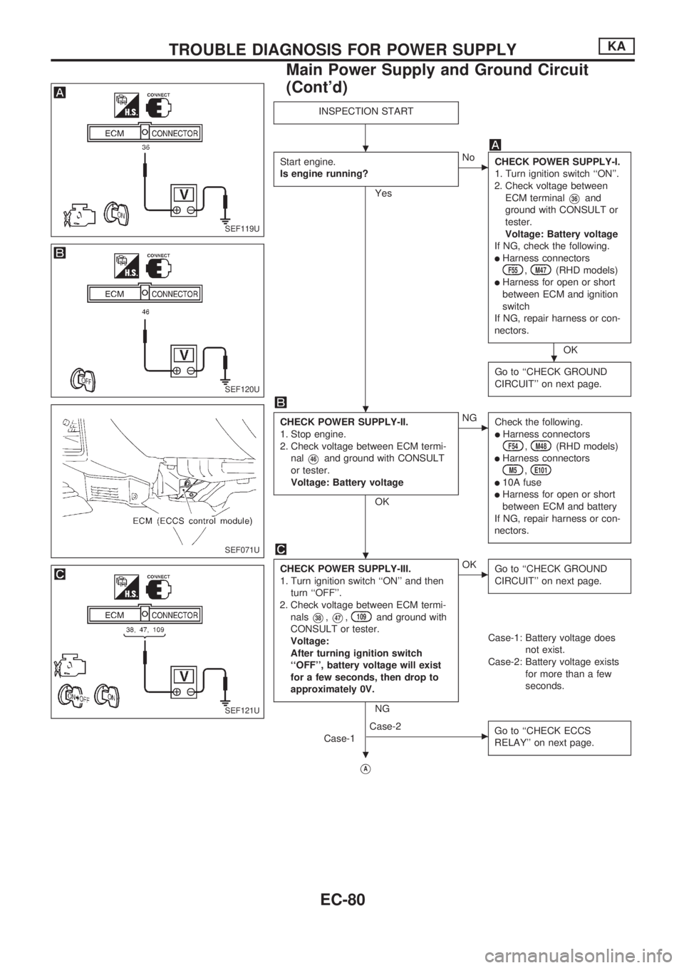
INSPECTION START
Start engine.
Is engine running?
Yes
cNo
CHECK POWER SUPPLY-I.
1. Turn ignition switch ``ON''.
2. Check voltage between
ECM terminal
V36and
ground with CONSULT or
tester.
Voltage: Battery voltage
If NG, check the following.
lHarness connectorsF55,M47(RHD models)
lHarness for open or short
between ECM and ignition
switch
If NG, repair harness or con-
nectors.
OK
Go to ``CHECK GROUND
CIRCUIT'' on next page.
CHECK POWER SUPPLY-II.
1. Stop engine.
2. Check voltage between ECM termi-
nal
V46and ground with CONSULT
or tester.
Voltage: Battery voltage
OK
cNG
Check the following.
lHarness connectorsF54,M48(RHD models)
lHarness connectorsM5,E101
l10A fuse
lHarness for open or short
between ECM and battery
If NG, repair harness or con-
nectors.
CHECK POWER SUPPLY-III.
1. Turn ignition switch ``ON'' and then
turn ``OFF''.
2. Check voltage between ECM termi-
nals
V38,V47,109and ground with
CONSULT or tester.
Voltage:
After turning ignition switch
``OFF'', battery voltage will exist
for a few seconds, then drop to
approximately 0V.
NG
cOK
Go to ``CHECK GROUND
CIRCUIT'' on next page.
Case-1: Battery voltage does
not exist.
Case-2: Battery voltage exists
for more than a few
seconds.
Case-1
cCase-2
Go to ``CHECK ECCS
RELAY'' on next page.
VA
SEF119U
SEF120U
SEF071U
SEF121U
.
.
.
.
.
TROUBLE DIAGNOSIS FOR POWER SUPPLYKA
Main Power Supply and Ground Circuit
(Cont'd)
EC-80
Page 233 of 1659
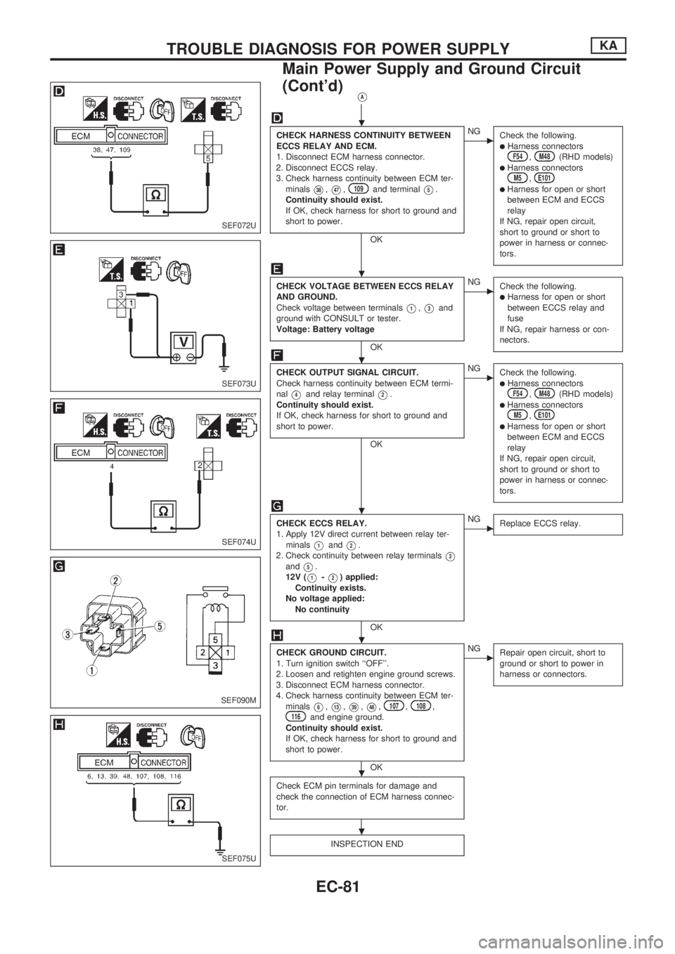
VA
CHECK HARNESS CONTINUITY BETWEEN
ECCS RELAY AND ECM.
1. Disconnect ECM harness connector.
2. Disconnect ECCS relay.
3. Check harness continuity between ECM ter-
minals
V38,V47,109and terminalV5.
Continuity should exist.
If OK, check harness for short to ground and
short to power.
OK
cNG
Check the following.
lHarness connectorsF54,M48(RHD models)lHarness connectorsM5,E101lHarness for open or short
between ECM and ECCS
relay
If NG, repair open circuit,
short to ground or short to
power in harness or connec-
tors.
CHECK VOLTAGE BETWEEN ECCS RELAY
AND GROUND.
Check voltage between terminals
V1,V3and
ground with CONSULT or tester.
Voltage: Battery voltage
OK
cNG
Check the following.
lHarness for open or short
between ECCS relay and
fuse
If NG, repair harness or con-
nectors.
CHECK OUTPUT SIGNAL CIRCUIT.
Check harness continuity between ECM termi-
nal
V4and relay terminalV2.
Continuity should exist.
If OK, check harness for short to ground and
short to power.
OK
cNG
Check the following.
lHarness connectorsF54,M48(RHD models)lHarness connectorsM5,E101lHarness for open or short
between ECM and ECCS
relay
If NG, repair open circuit,
short to ground or short to
power in harness or connec-
tors.
CHECK ECCS RELAY.
1. Apply 12V direct current between relay ter-
minals
V1andV2.
2. Check continuity between relay terminals
V3andV5.
12V (
V1-V2) applied:
Continuity exists.
No voltage applied:
No continuity
OK
cNG
Replace ECCS relay.
CHECK GROUND CIRCUIT.
1. Turn ignition switch ``OFF''.
2. Loosen and retighten engine ground screws.
3. Disconnect ECM harness connector.
4. Check harness continuity between ECM ter-
minals
V6,V13,V39,V48,107,108,116and engine ground.
Continuity should exist.
If OK, check harness for short to ground and
short to power.
OK
cNG
Repair open circuit, short to
ground or short to power in
harness or connectors.
Check ECM pin terminals for damage and
check the connection of ECM harness connec-
tor.
INSPECTION END
SEF072U
SEF073U
SEF074U
SEF090M
SEF075U
.
.
.
.
.
.
.
TROUBLE DIAGNOSIS FOR POWER SUPPLYKA
Main Power Supply and Ground Circuit
(Cont'd)
EC-81
Page 239 of 1659
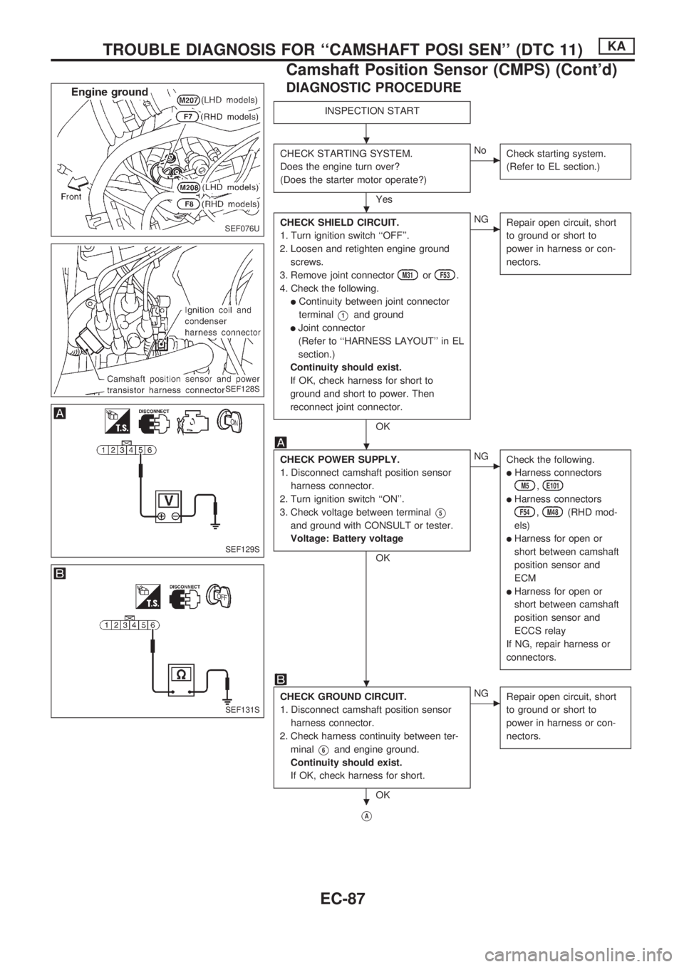
DIAGNOSTIC PROCEDURE
INSPECTION START
CHECK STARTING SYSTEM.
Does the engine turn over?
(Does the starter motor operate?)
Yes
cNo
Check starting system.
(Refer to EL section.)
CHECK SHIELD CIRCUIT.
1. Turn ignition switch ``OFF''.
2. Loosen and retighten engine ground
screws.
3. Remove joint connector
M31orF53.
4. Check the following.
lContinuity between joint connector
terminal
V1and ground
lJoint connector
(Refer to ``HARNESS LAYOUT'' in EL
section.)
Continuity should exist.
If OK, check harness for short to
ground and short to power. Then
reconnect joint connector.
OK
cNG
Repair open circuit, short
to ground or short to
power in harness or con-
nectors.
CHECK POWER SUPPLY.
1. Disconnect camshaft position sensor
harness connector.
2. Turn ignition switch ``ON''.
3. Check voltage between terminal
V5
and ground with CONSULT or tester.
Voltage: Battery voltage
OK
cNG
Check the following.
lHarness connectors
M5,E101
lHarness connectors
F54,M48(RHD mod-
els)
lHarness for open or
short between camshaft
position sensor and
ECM
lHarness for open or
short between camshaft
position sensor and
ECCS relay
If NG, repair harness or
connectors.
CHECK GROUND CIRCUIT.
1. Disconnect camshaft position sensor
harness connector.
2. Check harness continuity between ter-
minal
V6and engine ground.
Continuity should exist.
If OK, check harness for short.
OK
cNG
Repair open circuit, short
to ground or short to
power in harness or con-
nectors.
VA
SEF076U
SEF128S
SEF129S
SEF131S
.
.
.
.
.
TROUBLE DIAGNOSIS FOR ``CAMSHAFT POSI SEN'' (DTC 11)KA
Camshaft Position Sensor (CMPS) (Cont'd)
EC-87