1998 NISSAN PICK-UP relay
[x] Cancel search: relayPage 4 of 1659

How to Perform Trouble Diagnoses for Quick
and Accurate Repair ............................................ 38
Preliminary Check ................................................ 39
Component Parts and Harness Connector
Location................................................................ 40
Schematic/2WD Models....................................... 41
Wiring Diagram - ABS -/2WD LHD Models ......... 42
Wiring Diagram - ABS -/2WD RHD Models ........ 45
Schematic/4WD Models....................................... 48
Wiring Diagram - ABS -/4WD Models ................. 49
Self-diagnosis....................................................... 53
CONSULT ............................................................ 56
CONSULT Inspection Procedure......................... 57
Ground Circuit Check .......................................... 62
TROUBLE DIAGNOSES FOR
SELF-DIAGNOSTIC ITEMS.................................... 63
Diagnostic Procedure 1
(Wheel sensor or rotor)........................................ 63
Diagnostic Procedure 2 (ABS actuator
solenoid valve and solenoid valve relay)............. 65
Diagnostic Procedure 3 (Motor relay or motor) ... 67
Diagnostic Procedure 4 (Low voltage) ................ 69Diagnostic Procedure 5 (G sensor) ..................... 70
Diagnostic Procedure 6 (Control unit) ................. 71
TROUBLE DIAGNOSES FOR SYMPTOMS........... 72
Diagnostic Procedure 7
(ABS works frequently.) ....................................... 72
Diagnostic Procedure 8
(Unexpected pedal action) ................................... 73
Diagnostic Procedure 9
(Long stopping distance) ..................................... 73
Diagnostic Procedure 10
(ABS does not work.)........................................... 74
Diagnostic Procedure 11
(Pedal vibration and noise) .................................. 74
Diagnostic Procedure 12 (Warning lamp does
not come on when ignition switch is turned
ON.)...................................................................... 75
Diagnostic Procedure 13 (Warning lamp stays
on when ignition switch is turned ON.)................ 77
SERVICE DATA AND SPECIFICATIONS (SDS)... 78
General Specifications ......................................... 78
Inspection and Adjustment .................................. 80
When you read wiring diagrams:
lRead GI section, ``HOW TO READ WIRING DIAGRAMS''.
lSee EL section, ``POWER SUPPLY ROUTING'' for power distribution circuit.
When you perform trouble diagnoses, read GI section, ``HOW TO FOLLOW FLOW
CHART IN TROUBLE DIAGNOSES'' and ``HOW TO PERFORM EFFICIENT DIAGNOSIS
FOR AN ELECTRICAL INCIDENT''.
Page 37 of 1659

System Components
System Description
WHEEL SENSOR
The sensor unit consists of a gear-shaped sensor rotor and a
sensor element. The element contains a bar magnet around
which a coil is wound. The sensor is installed on the back of the
brake rotor and the front of the differential (2WD) or the back of
the rear brake drum (4WD). As the wheel rotates, the sensor
generates a sine-wave pattern. The frequency and voltage
increase(s) as the rotating speed increases.
CONTROL UNIT (built in ABS actuator and electric
unit)
The control unit computes the wheel rotating speed by the sig-
nal current sent from the sensor. Then it supplies a DC current
to the actuator solenoid valve. It also controls ON-OFF operation
of the valve relay and motor relay. If any electrical malfunction
should be detected in the system, the control unit causes the
warning lamp to light up. In this condition, the ABS will be deac-
tivated by the control unit, and the vehicle's brake system reverts
to normal operation. (For control unit layout, refer to ABS
ACTUATOR AND ELECTRIC UNIT, BR-34.)
SBR068E
SBR069E
ANTI-LOCK BRAKE SYSTEM
BR-33
Page 38 of 1659

G SENSOR (4WD models only)
The G sensor senses deceleration during braking to determine whether the vehicle is being driven on a high
road (asphalt road, etc.) or a low road (snow-covered road, etc.). It then sends a signal to the ABS con-
trol unit.
The reed switch turns on when it is affected by a magnetic field. During sudden deceleration (braking on a
high road), the weight moves and the magnet in the weight moves away from the reed switch. The mag-
netic field then diminishes and the reed switch turns off.
ABS ACTUATOR AND ELECTRIC UNIT
The ABS actuator and electric unit contains:
lAn electric motor and pump
lTwo relays
lSix solenoid valves, each inlet and outlet for
Ð LH front
Ð RH front
Ð Rear
lABS control unit
This component controls the hydraulic circuit and increases,
holds or decreases hydraulic pressure to all or individual wheels.
The ABS actuator and electric unit are not disassemble.
ABS actuator operation
Inlet solenoid
valveOutlet solenoid
valve
Normal brake operation OFF (Open) OFF (Closed)Master cylinder brake fluid pressure is directly trans-
mitted to wheel cylinder via the inlet solenoid valve.
ABS operationPressure hold ON (Closed) OFF (Closed)Hydraulic circuit is shut off to hold the wheel cylinder
brake fluid pressure.
Pressure
decreaseON (Closed) ON (Open)Wheel cylinder brake fluid is sent to reservoir via the
outlet solenoid valve. Then it is pushed up to the
master cylinder by pump.
Pressure
increaseOFF (Open) OFF (Closed)Master cylinder brake fluid pressure is transmitted to
wheel cylinder.
SBR070E
SBR071E
ANTI-LOCK BRAKE SYSTEM
System Description (Cont'd)
BR-34
Page 59 of 1659

MALFUNCTION CODE/SYMPTOM CHART
Code No.
(No. of warning lamp flashes)Malfunctioning part Diagnostic procedure
45 Actuator front left outlet solenoid valve 2
46 Actuator front left inlet solenoid valve 2
41 Actuator front right outlet solenoid valve 2
42 Actuator front right inlet solenoid valve 2
55 Actuator rear outlet solenoid valve 2
56 Actuator rear inlet solenoid valve 2
25.3 Front left sensor (open-circuit) 1
26.3 Front left sensor (short-circuit) 1
21.3 Front right sensor (open-circuit) 1
22.3 Front right sensor (short-circuit) 1
35.1,.3 Rear sensor (open-circuit) 1
36.1,.3 Rear sensor (short-circuit) 1
31.2,.3 Rear right sensor (open-circuit) 1
32.2,.3 Rear right sensor (short-circuit) 1
35.2,.3 Rear left sensor (open-circuit) 1
36.2,.3 Rear left sensor (short-circuit) 1
18.3 Sensor rotor 1
17.2 G sensor and circuit 5
61.5 Actuator motor or motor relay 3
63 Solenoid valve relay 2
57.4 Power supply (Low voltage) 4
71 Control unit 6
Warning lamp stays on when igni-
tion switch is turned onControl unit power supply circuit
Warning lamp bulb circuit
Control unit or control unit connector
Solenoid valve relay stuck
Power supply for solenoid valve relay coil13
Warning lamp does not come on
when ignition switch is turned onFuse, warning lamp bulb or warning lamp circuit
Control unit12
Pedal vibration and noise Ð 11
Long stopping distance Ð 9
Unexpected pedal action Ð 8
ABS does not work Ð 10
ABS works frequently Ð 7
.1: 2WD model only
.2: 4WD model only
.3: If one or more wheels spin on a rough or slippery road for 40 seconds or more, the ABS warning lamp will illuminate. This does
not indicate a malfunction. Only in the case of the short-circuit (Code Nos. 26, 22, 32 and 36), after repair the ABS warning
lamp also illuminates when the ignition switch is turned ``ON''. In this case, drive the vehicle at speeds greater than 30 km/h (19
MPH) for approximately 1 minute as specified in ``SELF-DIAGNOSIS PROCEDURE'', BR-53. Check to ensure that the ABS
warning lamp goes out while the vehicle is being driven.
.4: The trouble code ``57'', which refers to a low power supply voltage, does not indicate that the ABS control unit is malfunctioning.
Do not replace the ABS control unit with a new one.
.5: The trouble code ``61'' can sometimes appear when the ABS motor is not properly grounded. If it appears, be sure to check the
condition of the ABS motor ground circuit connection.
TROUBLE DIAGNOSES
Self-diagnosis (Cont'd)
BR-55
Page 60 of 1659

CONSULT
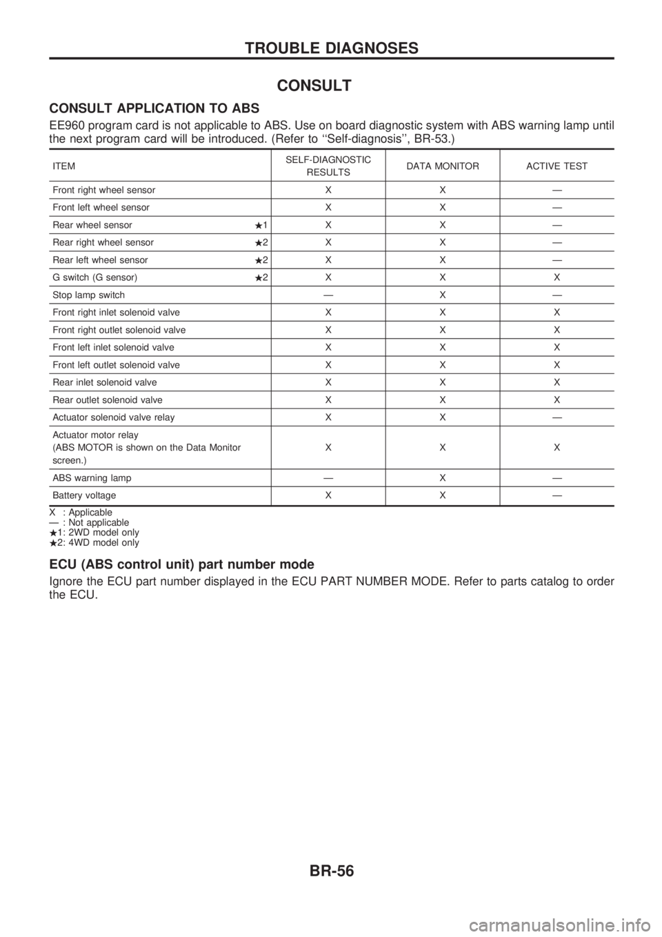
CONSULT APPLICATION TO ABS
EE960 program card is not applicable to ABS. Use on board diagnostic system with ABS warning lamp until
the next program card will be introduced. (Refer to ``Self-diagnosis'', BR-53.)
ITEMSELF-DIAGNOSTIC
RESULTSDATA MONITOR ACTIVE TEST
Front right wheel sensor X X Ð
Front left wheel sensor X X Ð
Rear wheel sensor.1X X Ð
Rear right wheel sensor.2X X Ð
Rear left wheel sensor.2X X Ð
G switch (G sensor).2XXX
Stop lamp switch Ð X Ð
Front right inlet solenoid valve X X X
Front right outlet solenoid valve X X X
Front left inlet solenoid valve X X X
Front left outlet solenoid valve X X X
Rear inlet solenoid valve X X X
Rear outlet solenoid valve X X X
Actuator solenoid valve relay X X Ð
Actuator motor relay
(ABS MOTOR is shown on the Data Monitor
screen.)XXX
ABS warning lamp Ð X Ð
Battery voltage X X Ð
X : Applicable
Ð : Not applicable
.1: 2WD model only
.2: 4WD model only
ECU (ABS control unit) part number mode
Ignore the ECU part number displayed in the ECU PART NUMBER MODE. Refer to parts catalog to order
the ECU.
TROUBLE DIAGNOSES
BR-56
Page 62 of 1659
![NISSAN PICK-UP 1998 Repair Manual SELF-DIAGNOSTIC RESULTS MODE
Diagnostic item Diagnostic item is detected when ...Diagnostic
procedure
FR RH SENSOR.1
[OPEN]
lCircuit for front right wheel sensor is open.
(An abnormally high input vol NISSAN PICK-UP 1998 Repair Manual SELF-DIAGNOSTIC RESULTS MODE
Diagnostic item Diagnostic item is detected when ...Diagnostic
procedure
FR RH SENSOR.1
[OPEN]
lCircuit for front right wheel sensor is open.
(An abnormally high input vol](/manual-img/5/57374/w960_57374-61.png)
SELF-DIAGNOSTIC RESULTS MODE
Diagnostic item Diagnostic item is detected when ...Diagnostic
procedure
FR RH SENSOR.1
[OPEN]
lCircuit for front right wheel sensor is open.
(An abnormally high input voltage is entered.)1
FR LH SENSOR.1
[OPEN]
lCircuit for front left wheel sensor is open.
(An abnormally high input voltage is entered.)1
RR SENSOR.1,.2
[OPEN]
lCircuit for rear sensor is open.
(An abnormal high input voltage is entered.)1
RR RH SENSOR.1,.3
[OPEN]
lCircuit for rear right sensor is open.
(An abnormally high input voltage is entered.)1
RR LH SENSOR.1,.3
[OPEN]
lCircuit for rear left sensor is open.
(An abnormally high input voltage is entered.)1
FR RH SENSOR.1
[SHORT]
lCircuit for front right wheel sensor is shorted.
(An abnormally low input voltage is entered.)1
FR LH SENSOR.1
[SHORT]
lCircuit for front left wheel sensor is shorted.
(An abnormally low input voltage is entered.)1
RR SENSOR.1,.2
[SHORT]
lCircuit for rear sensor is shorted.
(An abnormal low input voltage is entered.)1
RR RH SENSOR.1,.3
[SHORT]
lCircuit for rear right sensor is shorted.
(An abnormally low input voltage is entered.)1
RR LH SENSOR.1,.3
[SHORT]
lCircuit for rear left sensor is shorted.
(An abnormally low input voltage is entered.)1
ABS SENSOR.1
[ABNORMAL SIGNAL]
lTeeth damage on sensor rotor or improper installation of wheel sensor.
(Abnormal wheel sensor signal is entered.)1
FR RH IN ABS SOL
[OPEN]
lCircuit for front right inlet solenoid valve is open.
(An abnormally low output voltage is entered.)2
FR LH IN ABS SOL
[OPEN]
lCircuit for front left inlet solenoid valve is open.
(An abnormally low output voltage is entered.)2
RR IN ABS SOL
[OPEN]
lCircuit for rear inlet solenoid valve is open.
(An abnormally low output voltage is entered.)2
FR RH IN ABS SOL
[SHORT]
lCircuit for front right inlet solenoid valve is shorted.
(An abnormally high output voltage is entered.)2
FR LH IN ABS SOL
[SHORT]
lCircuit for front left inlet solenoid valve is shorted.
(An abnormally high output voltage is entered.)2
RR IN ABS SOL
[SHORT]
lCircuit for rear inlet solenoid valve is shorted.
(An abnormally high output voltage is entered.)2
FR RH OUT ABS SOL
[OPEN]
lCircuit for front right outlet solenoid valve is open.
(An abnormally low output voltage is entered.)2
FR LH OUT ABS SOL
[OPEN]
lCircuit for front left outlet solenoid valve is open.
(An abnormally low output voltage is entered.)2
RR OUT ABS SOL
[OPEN]
lCircuit for rear outlet solenoid valve is open.
(An abnormally low output voltage is entered.)2
FR RH OUT ABS SOL
[SHORT]
lCircuit for front right outlet solenoid valve is shorted.
(An abnormally high output voltage is entered.)2
FR LH OUT ABS SOL
[SHORT]
lCircuit for front left outlet solenoid valve is shorted.
(An abnormally high output voltage is entered.)2
RR OUT ABS SOL
[SHORT]
lCircuit for rear outlet solenoid valve is shorted.
(An abnormally high output voltage is entered.)2
ABS ACTUATOR RELAY
[ABNORMAL]
lActuator solenoid valve relay is ON, even if control unit sends off signal.lActuator solenoid valve relay is OFF, even if control unit sends on signal.2
ABS MOTOR RELAY
[ABNORMAL]
lCircuit for ABS motor relay is open or shorted.lCircuit for actuator motor is open or shorted.lActuator motor relay is stuck.3
BATTERY VOLT
[VB-LOW]
lPower source voltage supplied to ABS control unit is abnormally low. 4
CONTROL UNIT
lFunction of calculation in ABS control unit has failed. 6
G-SENSOR.3
[ABNORMAL]
lG sensor circuit is open or shorted. 5
.1: If one or more wheels spin on a rough or slippery road for 40 seconds or more, the ABS warning lamp will illuminate. This
does not indicate a malfunction. Only in the case of the short-circuit (Code Nos. 26, 22, 32 and 36), after repair the ABS warn-
ing lamp also illuminates when the ignition switch is turned ``ON''. In this case, drive the vehicle at speeds greater than 30 km/h
(19 MPH) for approximately 1 minute as specified in ``SELF-DIAGNOSIS PROCEDURE'', BR-53. Check to ensure that the ABS
warning lamp goes out while the vehicle is being driven.
.2: 2WD model only
.3: 4WD model only
TROUBLE DIAGNOSES
CONSULT Inspection Procedure (Cont'd)
BR-58
Page 65 of 1659

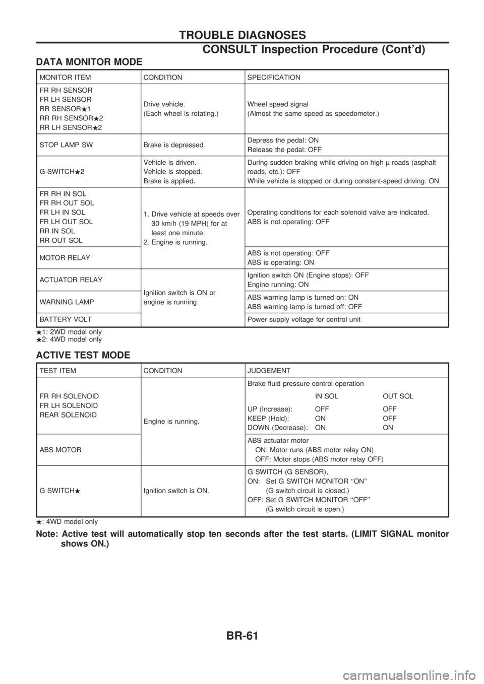
DATA MONITOR MODE
MONITOR ITEM CONDITION SPECIFICATION
FR RH SENSOR
FR LH SENSOR
RR SENSOR.1
RR RH SENSOR.2
RR LH SENSOR.2Drive vehicle.
(Each wheel is rotating.)Wheel speed signal
(Almost the same speed as speedometer.)
STOP LAMP SW Brake is depressed.Depress the pedal: ON
Release the pedal: OFF
G-SWITCH.2Vehicle is driven.
Vehicle is stopped.
Brake is applied.During sudden braking while driving on high roads (asphalt
roads, etc.): OFF
While vehicle is stopped or during constant-speed driving: ON
FR RH IN SOL
FR RH OUT SOL
FR LH IN SOL
FR LH OUT SOL
RR IN SOL
RR OUT SOL1. Drive vehicle at speeds over
30 km/h (19 MPH) for at
least one minute.
2. Engine is running.Operating conditions for each solenoid valve are indicated.
ABS is not operating: OFF
MOTOR RELAYABS is not operating: OFF
ABS is operating: ON
ACTUATOR RELAY
Ignition switch is ON or
engine is running.Ignition switch ON (Engine stops): OFF
Engine running: ON
WARNING LAMPABS warning lamp is turned on: ON
ABS warning lamp is turned off: OFF
BATTERY VOLT Power supply voltage for control unit
.1: 2WD model only
.2: 4WD model only
ACTIVE TEST MODE
TEST ITEM CONDITION JUDGEMENT
FR RH SOLENOID
FR LH SOLENOID
REAR SOLENOID
Engine is running.Brake fluid pressure control operation
IN SOL OUT SOL
UP (Increase):
KEEP (Hold):
DOWN (Decrease):OFF
ON
ONOFF
OFF
ON
ABS MOTORABS actuator motor
ON: Motor runs (ABS motor relay ON)
OFF: Motor stops (ABS motor relay OFF)
G SWITCH.Ignition switch is ON.G SWITCH (G SENSOR),
ON: Set G SWITCH MONITOR ``ON''
(G switch circuit is closed.)
OFF: Set G SWITCH MONITOR ``OFF''
(G switch circuit is open.)
.: 4WD model only
Note: Active test will automatically stop ten seconds after the test starts. (LIMIT SIGNAL monitor
shows ON.)
TROUBLE DIAGNOSES
CONSULT Inspection Procedure (Cont'd)
BR-61
Page 69 of 1659

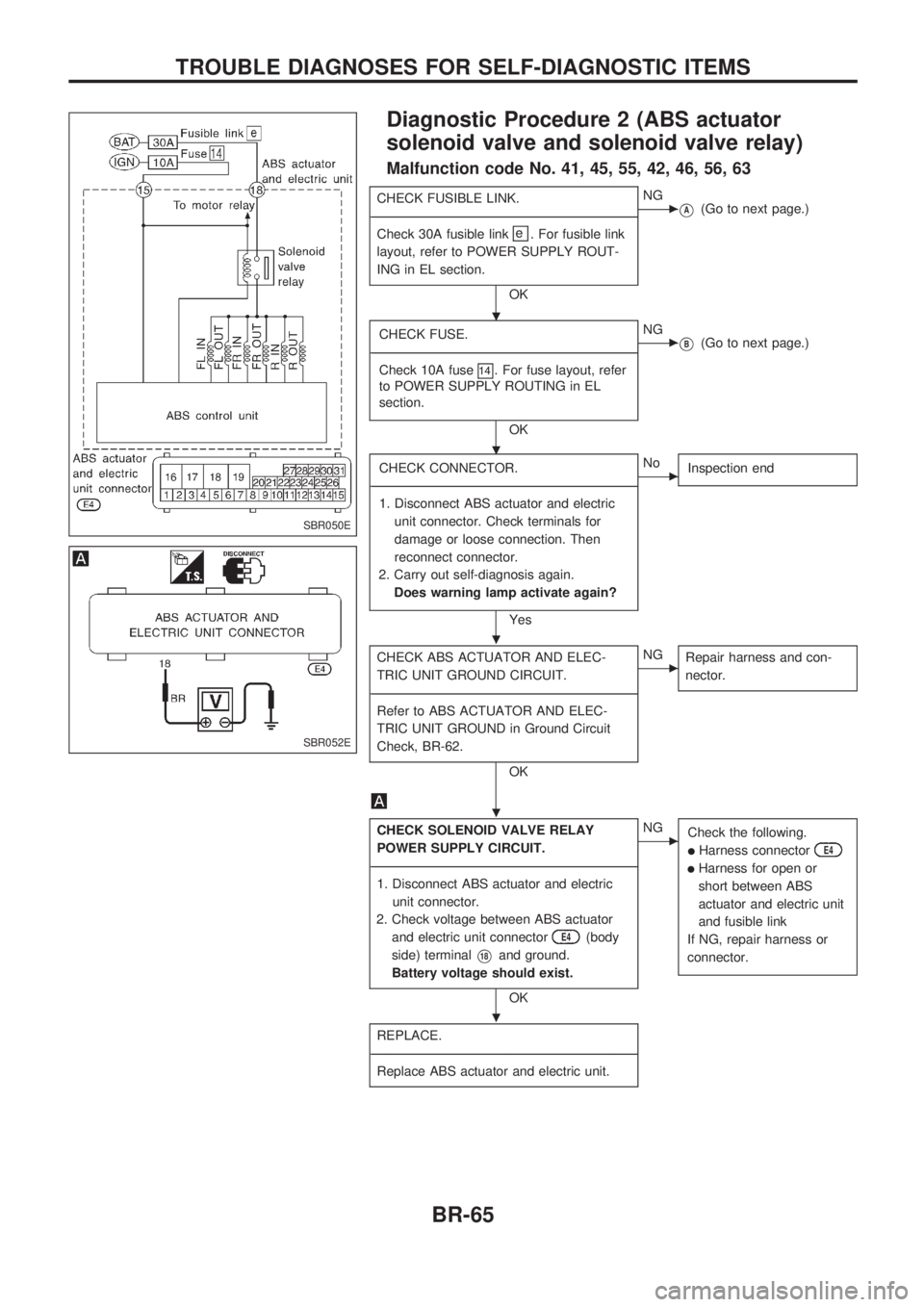
Diagnostic Procedure 2 (ABS actuator
solenoid valve and solenoid valve relay)
Malfunction code No. 41, 45, 55, 42, 46, 56, 63
CHECK FUSIBLE LINK.
-------------------------------------------------------------------------------------------------------------------------------------------------------------------------------------------------------------------------------------------------------------------------------------------------------------
Check 30A fusible link
e
. For fusible link
layout, refer to POWER SUPPLY ROUT-
ING in EL section.
OK
cNG
VA(Go to next page.)
CHECK FUSE.
-------------------------------------------------------------------------------------------------------------------------------------------------------------------------------------------------------------------------------------------------------------------------------------------------------------
Check 10A fuse
14. For fuse layout, refer
to POWER SUPPLY ROUTING in EL
section.
OK
cNG
VB(Go to next page.)
CHECK CONNECTOR.
-------------------------------------------------------------------------------------------------------------------------------------------------------------------------------------------------------------------------------------------------------------------------------------------------------------
1. Disconnect ABS actuator and electric
unit connector. Check terminals for
damage or loose connection. Then
reconnect connector.
2. Carry out self-diagnosis again.
Does warning lamp activate again?
Yes
cNo
Inspection end
CHECK ABS ACTUATOR AND ELEC-
TRIC UNIT GROUND CIRCUIT.
-------------------------------------------------------------------------------------------------------------------------------------------------------------------------------------------------------------------------------------------------------------------------------------------------------------
Refer to ABS ACTUATOR AND ELEC-
TRIC UNIT GROUND in Ground Circuit
Check, BR-62.
OK
cNG
Repair harness and con-
nector.
CHECK SOLENOID VALVE RELAY
POWER SUPPLY CIRCUIT.
-------------------------------------------------------------------------------------------------------------------------------------------------------------------------------------------------------------------------------------------------------------------------------------------------------------
1. Disconnect ABS actuator and electric
unit connector.
2. Check voltage between ABS actuator
and electric unit connector
E4(body
side) terminal
V18and ground.
Battery voltage should exist.
OK
cNG
Check the following.
lHarness connectorE4
lHarness for open or
short between ABS
actuator and electric unit
and fusible link
If NG, repair harness or
connector.
REPLACE.
-------------------------------------------------------------------------------------------------------------------------------------------------------------------------------------------------------------------------------------------------------------------------------------------------------------
Replace ABS actuator and electric unit.
SBR050E
SBR052E
.
.
.
.
.
TROUBLE DIAGNOSES FOR SELF-DIAGNOSTIC ITEMS
BR-65