1998 NISSAN PICK-UP relay
[x] Cancel search: relayPage 70 of 1659
VA
REPLACE.
-------------------------------------------------------------------------------------------------------------------------------------------------------------------------------------------------------------------------------------------------------------------------------------------------------------
Replace fusible link.
Does the fusible link blow out when
ignition switch is turned ``ON''?
Yes
cNo
Inspection end
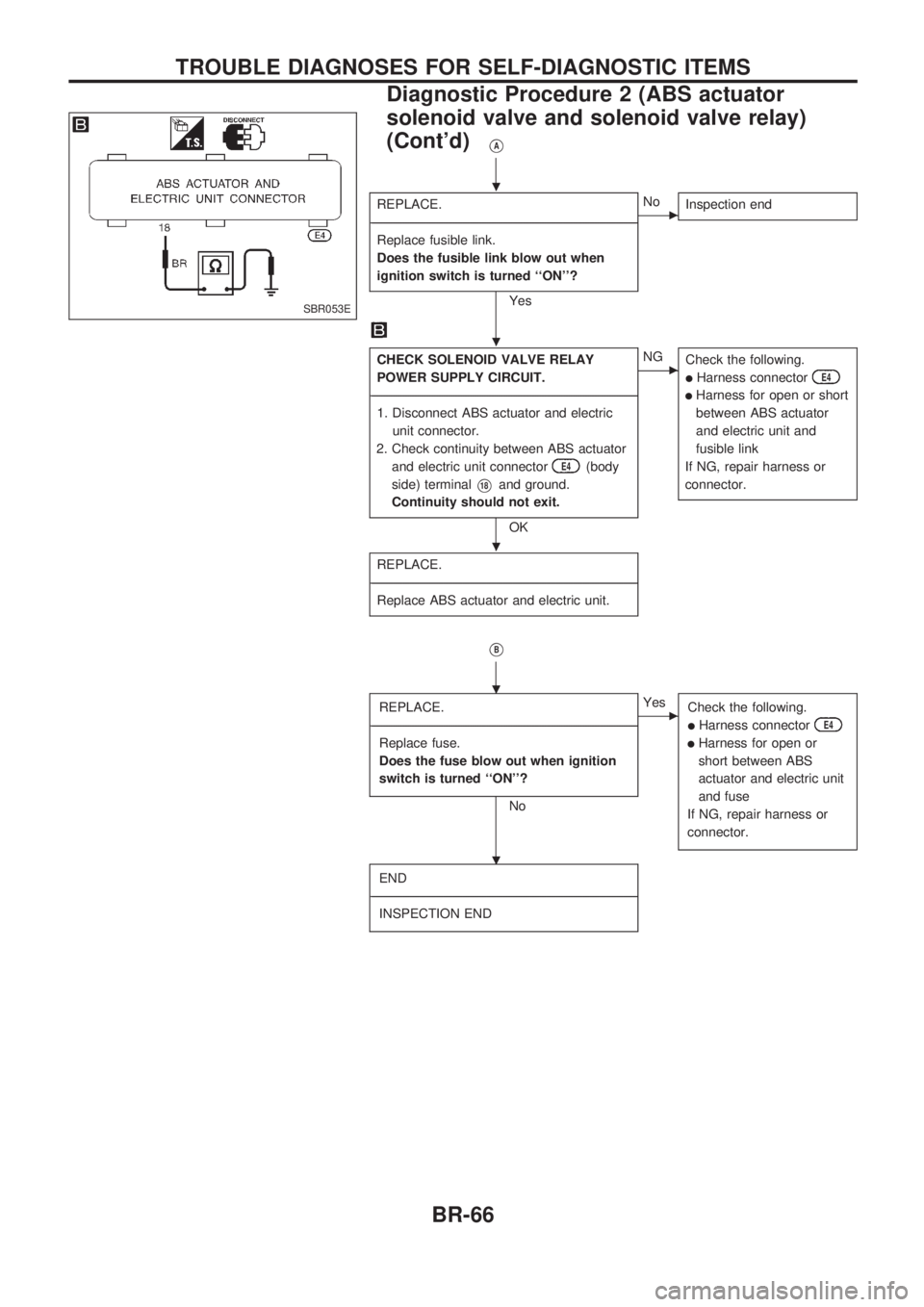
CHECK SOLENOID VALVE RELAY
POWER SUPPLY CIRCUIT.
-------------------------------------------------------------------------------------------------------------------------------------------------------------------------------------------------------------------------------------------------------------------------------------------------------------
1. Disconnect ABS actuator and electric
unit connector.
2. Check continuity between ABS actuator
and electric unit connector
E4(body
side) terminal
V18and ground.
Continuity should not exit.
OK
cNG
Check the following.
lHarness connectorE4
lHarness for open or short
between ABS actuator
and electric unit and
fusible link
If NG, repair harness or
connector.
REPLACE.
-------------------------------------------------------------------------------------------------------------------------------------------------------------------------------------------------------------------------------------------------------------------------------------------------------------
Replace ABS actuator and electric unit.
VB
REPLACE.
-------------------------------------------------------------------------------------------------------------------------------------------------------------------------------------------------------------------------------------------------------------------------------------------------------------
Replace fuse.
Does the fuse blow out when ignition
switch is turned ``ON''?
No
cYes
Check the following.
lHarness connectorE4
lHarness for open or
short between ABS
actuator and electric unit
and fuse
If NG, repair harness or
connector.
END
-------------------------------------------------------------------------------------------------------------------------------------------------------------------------------------------------------------------------------------------------------------------------------------------------------------
INSPECTION END
SBR053E
.
.
.
.
.
TROUBLE DIAGNOSES FOR SELF-DIAGNOSTIC ITEMS
Diagnostic Procedure 2 (ABS actuator
solenoid valve and solenoid valve relay)
(Cont'd)
BR-66
Page 71 of 1659
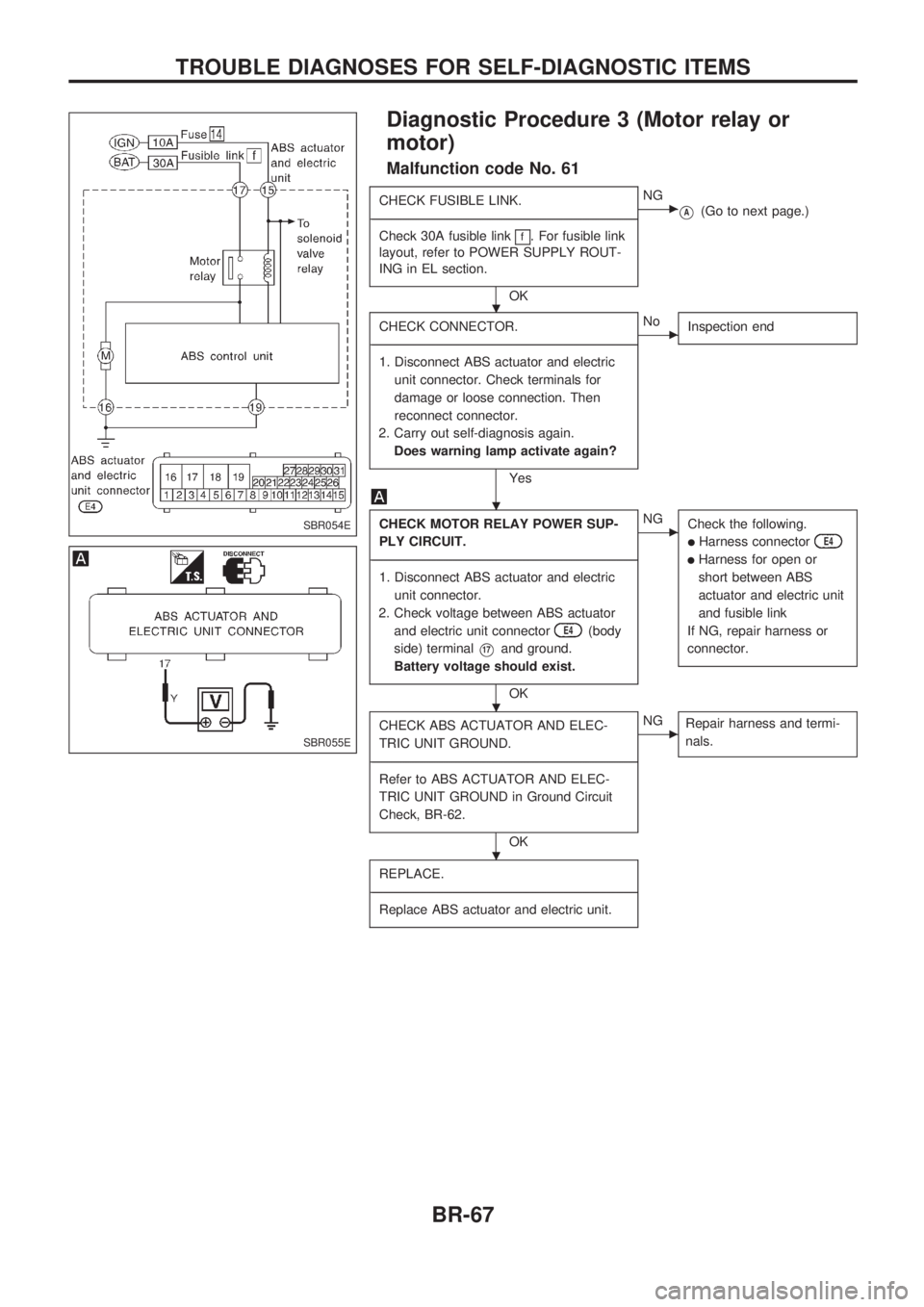
Diagnostic Procedure 3 (Motor relay or
motor)
Malfunction code No. 61
CHECK FUSIBLE LINK.
-------------------------------------------------------------------------------------------------------------------------------------------------------------------------------------------------------------------------------------------------------------------------------------------------------------
Check 30A fusible link
f. For fusible link
layout, refer to POWER SUPPLY ROUT-
ING in EL section.
OK
cNG
VA(Go to next page.)
CHECK CONNECTOR.
-------------------------------------------------------------------------------------------------------------------------------------------------------------------------------------------------------------------------------------------------------------------------------------------------------------
1. Disconnect ABS actuator and electric
unit connector. Check terminals for
damage or loose connection. Then
reconnect connector.
2. Carry out self-diagnosis again.
Does warning lamp activate again?
Yes
cNo
Inspection end
CHECK MOTOR RELAY POWER SUP-
PLY CIRCUIT.
-------------------------------------------------------------------------------------------------------------------------------------------------------------------------------------------------------------------------------------------------------------------------------------------------------------
1. Disconnect ABS actuator and electric
unit connector.
2. Check voltage between ABS actuator
and electric unit connector
E4(body
side) terminal
V17and ground.
Battery voltage should exist.
OK
cNG
Check the following.
lHarness connectorE4
lHarness for open or
short between ABS
actuator and electric unit
and fusible link
If NG, repair harness or
connector.
CHECK ABS ACTUATOR AND ELEC-
TRIC UNIT GROUND.
-------------------------------------------------------------------------------------------------------------------------------------------------------------------------------------------------------------------------------------------------------------------------------------------------------------
Refer to ABS ACTUATOR AND ELEC-
TRIC UNIT GROUND in Ground Circuit
Check, BR-62.
OK
cNG
Repair harness and termi-
nals.
REPLACE.
-------------------------------------------------------------------------------------------------------------------------------------------------------------------------------------------------------------------------------------------------------------------------------------------------------------
Replace ABS actuator and electric unit.
SBR054E
SBR055E
.
.
.
.
TROUBLE DIAGNOSES FOR SELF-DIAGNOSTIC ITEMS
BR-67
Page 72 of 1659
VA
REPLACE.
-------------------------------------------------------------------------------------------------------------------------------------------------------------------------------------------------------------------------------------------------------------------------------------------------------------
Replace fusible link.
Does the fusible link blow out when
ignition switch is turned ``ON''?
Yes
cNo
Inspection end
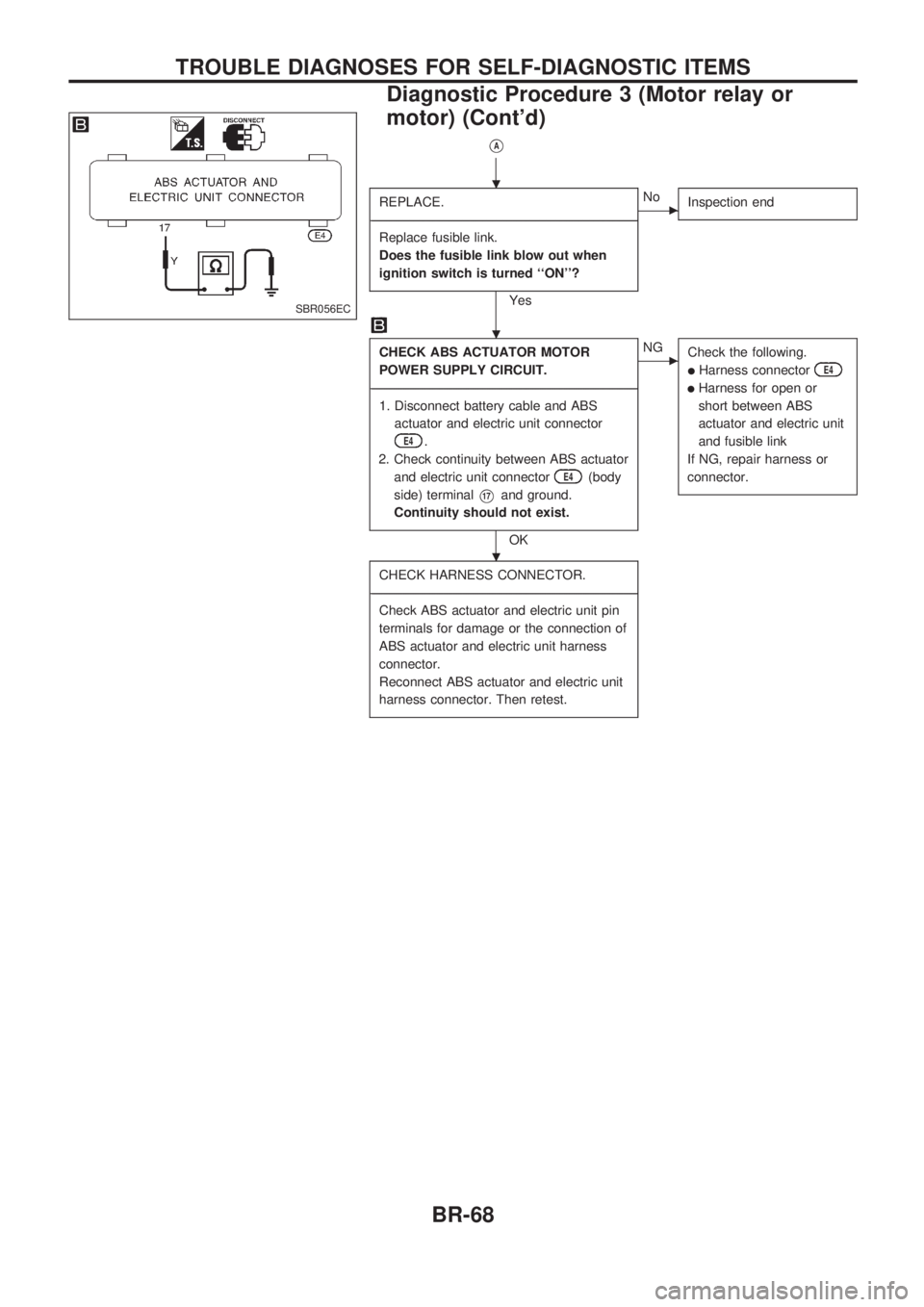
CHECK ABS ACTUATOR MOTOR
POWER SUPPLY CIRCUIT.
-------------------------------------------------------------------------------------------------------------------------------------------------------------------------------------------------------------------------------------------------------------------------------------------------------------
1. Disconnect battery cable and ABS
actuator and electric unit connector
E4.
2. Check continuity between ABS actuator
and electric unit connector
E4(body
side) terminal
V17and ground.
Continuity should not exist.
OK
cNG
Check the following.
lHarness connectorE4
lHarness for open or
short between ABS
actuator and electric unit
and fusible link
If NG, repair harness or
connector.
CHECK HARNESS CONNECTOR.
-------------------------------------------------------------------------------------------------------------------------------------------------------------------------------------------------------------------------------------------------------------------------------------------------------------
Check ABS actuator and electric unit pin
terminals for damage or the connection of
ABS actuator and electric unit harness
connector.
Reconnect ABS actuator and electric unit
harness connector. Then retest.
SBR056EC
.
.
.
TROUBLE DIAGNOSES FOR SELF-DIAGNOSTIC ITEMS
Diagnostic Procedure 3 (Motor relay or
motor) (Cont'd)
BR-68
Page 165 of 1659

System Chart
Camshaft position sensorc
ECM
(ECCS
control
module)
Mass air flow sensorc
Engine coolant temperature sensorc
Heated oxygen sensor*c
Ignition switchc
Throttle position sensorc
Neutral position switchc
Vehicle speed sensorc
Air conditioner switchc
Battery voltagec
Power steering oil pressure switchc
Intake air temperature sensorc
*: LHD models
Fuel injection &
mixture ratio controlcInjectors
Distributor ignition systemcPower transistor
Idle air control systemcIACV-AAC valve
IACV-FICD solenoid valve
Swirl control valve controlcSwirl control valve control
solenoid valve
EVAP canister controlcEVAP canister purge control
solenoid valve
Fuel pump controlcFuel pump relay
Heated oxygen sensor moni-
tor & on board diagnostic
systemcMalfunction indicator lamp
(On the instrument panel)
Acceleration cut controlcAir conditioner relay
Heated oxygen sensor
heater control*cHeated oxygen sensor
heater
ENGINE AND EMISSION CONTROL OVERALL SYSTEMKA
EC-13
Page 170 of 1659

Air Conditioning Cut Control
INPUT/OUTPUT SIGNAL LINE
Air conditioner switchcAir conditioner ``ON'' signal
ECM
(ECCS
control
module)
cAir condi-
tioner
relayThrottle position sensorcThrottle valve opening angle
Ignition switch
cStart signal
Engine coolant temperature sensor
cEngine coolant temperature
SYSTEM DESCRIPTION
This system improves engine operation when the
air conditioner is used.
Under the following conditions, the air conditioner
is turned off.
lWhen the accelerator pedal is fully depressed
lWhen cranking the engine
lWhen the engine coolant temperature becomes
excessively high
Fuel Cut Control (at no load & high engine
speed)
INPUT/OUTPUT SIGNAL LINE
Vehicle speed sensorcVehicle speed
ECM
(ECCS
control
module)
cInjectors
Neutral position switchcNeutral position
Throttle position sensor
cThrottle position
Engine coolant temperature sensor
cEngine coolant temperature
Camshaft position sensor
cEngine speed
If the engine speed is above 3,500 rpm with no load (for
example, in neutral and engine speed over 3,500 rpm) fuel will
be cut off after some time. The exact time when the fuel is cut
off varies based on engine speed.
Fuel cut will operate until the engine speed reaches 1,500 rpm,
then fuel cut is cancelled.
NOTE:
This function is different than deceleration control listed
under multiport fuel injection on EC-14.
ENGINE AND EMISSION BASIC CONTROL SYSTEM DESCRIPTIONKA
EC-18
Page 199 of 1659
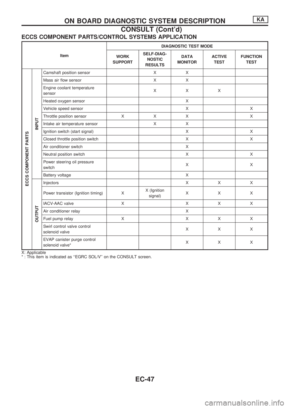
ECCS COMPONENT PARTS/CONTROL SYSTEMS APPLICATION
ItemDIAGNOSTIC TEST MODE
WORK
SUPPORTSELF-DIAG-
NOSTIC
RESULTSDATA
MONITORACTIVE
TESTFUNCTION
TEST
ECCS COMPONENT PARTS
INPUT
Camshaft position sensor X X
Mass air flow sensor X X
Engine coolant temperature
sensorXXX
Heated oxygen sensor X
Vehicle speed sensor X X
Throttle position sensor X X X X
Intake air temperature sensor X X
Ignition switch (start signal) X X
Closed throttle position switch X X
Air conditioner switch X
Neutral position switch X X
Power steering oil pressure
switchXX
Battery voltage X
OUTPUT
Injectors X X X
Power transistor (Ignition timing) XX (Ignition
signal)XXX
IACV-AAC valve X X X X
Air conditioner relay X
Fuel pump relay X X X X
Swirl control valve control
solenoid valveXXX
EVAP canister purge control
solenoid valve*XXX
X: Applicable
* : This item is indicated as ``EGRC SOL/V'' on the CONSULT screen.
ON BOARD DIAGNOSTIC SYSTEM DESCRIPTIONKA
CONSULT (Cont'd)
EC-47
Page 201 of 1659
![NISSAN PICK-UP 1998 Repair Manual Monitored item
[Unit]ECM
input
signalsMain
signalsDescription Remarks
INJ PULSE [msec]
j
lIndicates the actual fuel injection pulse
width compensated by ECM according to
the input signals.lWhen the en NISSAN PICK-UP 1998 Repair Manual Monitored item
[Unit]ECM
input
signalsMain
signalsDescription Remarks
INJ PULSE [msec]
j
lIndicates the actual fuel injection pulse
width compensated by ECM according to
the input signals.lWhen the en](/manual-img/5/57374/w960_57374-200.png)
Monitored item
[Unit]ECM
input
signalsMain
signalsDescription Remarks
INJ PULSE [msec]
j
lIndicates the actual fuel injection pulse
width compensated by ECM according to
the input signals.lWhen the engine is stopped, a certain
computed value is indicated.
IGN TIMING [BTDC]
j
lIndicates the ignition timing computed by
ECM according to the input signals.lWhen the engine is stopped, a certain
value is indicated.
IACV-AAC/V [%]
j
lIndicates the idle air control valve (AAC
valve) control value computed by ECM
according to the input signals.
A/F ALPHA [%]
j
lThe mean value of the air-fuel ratio feed-
back correction factor per cycle is indi-
cated.lWhen the engine is stopped, a certain
value is indicated.
lThis data also includes the data for the
air-fuel ratio learning control.
AIR COND RLY
[ON/OFF]
j
lThe air conditioner relay control condition
(determined by ECM according to the
input signal) is indicated.
FUEL PUMP RLY
[ON/OFF]
j
lIndicates the fuel pump relay control con-
dition determined by ECM according to
the input signals.
SWRL CONT S/V
[ON/OFF]
j
lThe control condition of the swirl control
valve control solenoid valve (determined
by the ECM according to the input signal)
is indicated.
ON ... Swirl control valve is closed
OFF ... Swirl control valve is open
EGRC SOL/V
(EVAP canister purge
control solenoid
valve) [ON/OFF]
j
lThe control condition of the EVAP canis-
ter purge control solenoid valve (deter-
mined by ECM according to the input
signal) is indicated.
ON ... EVAP canister purge control is not
operating
OFF ... EVAP canister purge control is
operational.
VOLTAGE
[V]
lVoltage measured by the voltage probe.
PULSE
[msec] or [Hz] or [%]
lPulse width, frequency or duty cycle
measured by the pulse probe.lOnly ``#'' is displayed if item is unable to
be measured.
lFigures with ``#''s are temporary ones.
They are the same figures as an actual
piece of data which was just previously
measured.
ON BOARD DIAGNOSTIC SYSTEM DESCRIPTIONKA
CONSULT (Cont'd)
EC-49
Page 202 of 1659
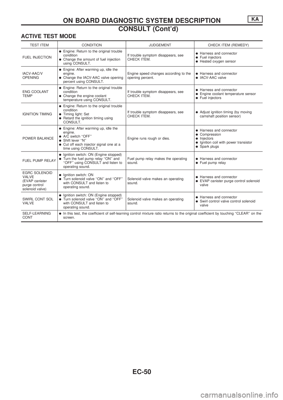
ACTIVE TEST MODE
TEST ITEM CONDITION JUDGEMENT CHECK ITEM (REMEDY)
FUEL INJECTION
lEngine: Return to the original trouble
condition
lChange the amount of fuel injection
using CONSULT.If trouble symptom disappears, see
CHECK ITEM.
lHarness and connectorlFuel injectorslHeated oxygen sensor
IACV-AAC/V
OPENING
lEngine: After warming up, idle the
engine.
lChange the IACV-AAC valve opening
percent using CONSULT.Engine speed changes according to the
opening percent.lHarness and connectorlIACV-AAC valve
ENG COOLANT
TEMP
lEngine: Return to the original trouble
condition
lChange the engine coolant
temperature using CONSULT.If trouble symptom disappears, see
CHECK ITEM.
lHarness and connectorlEngine coolant temperature sensorlFuel injectors
IGNITION TIMING
lEngine: Return to the original trouble
condition
lTiming light: SetlRetard the ignition timing using
CONSULT.If trouble symptom disappears, see
CHECK ITEM.
lAdjust ignition timing (by moving
camshaft position sensor)
POWER BALANCE
lEngine: After warming up, idle the
engine.
lA/C switch ``OFF''lShift lever ``N''lCut off each injector signal one at a
time using CONSULT.Engine runs rough or dies.
lHarness and connectorlCompressionlInjectorslIgnition coil with power transistorlSpark plugs
FUEL PUMP RELAY
lIgnition switch: ON (Engine stopped)lTurn the fuel pump relay ``ON'' and
``OFF'' using CONSULT and listen to
operating sound.Fuel pump relay makes the operating
sound.lHarness and connectorlFuel pump relay
EGRC SOLENOID
VALVE
(EVAP canister
purge control
solenoid valve)
lIgnition switch: ONlTurn solenoid valve ``ON'' and ``OFF''
with CONSULT and listen to
operating sound.Solenoid valve makes an operating
sound.lHarness and connectorlEVAP canister purge control solenoid
valve
SWIRL CONT SOL
VALVE
lIgnition switch: ON (Engine stopped)lTurn solenoid valve ``ON'' and ``OFF''
with CONSULT and listen to
operating sound.Solenoid valve makes an operating
sound.lHarness and connectorlSwirl control valve control solenoid
valve
SELF-LEARNING
CONT
lIn this test, the coefficient of self-learning control mixture ratio returns to the original coefficient by touching ``CLEAR'' on the
screen.
ON BOARD DIAGNOSTIC SYSTEM DESCRIPTIONKA
CONSULT (Cont'd)
EC-50