Page 9 of 75

1. Ensure vehicle is unladen condition*.* Fuel, radiator coolant and engine oil full. Spare tire, jack,hand tools and mats in designated positions.
2. Have a driver sit in the driver's seat and one person sit on the rear end. Then have the person on the rear end slowly get off
the vehicle. This is necessary to stabilize suspension de¯ec-
tion.
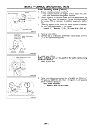
3. Gradually depress brake pedal and attach a lever to the stop- per bolt, then adjust length ``L'' as follows:Length ``L'': Approx. 175.2 - 178.2 mm (6.90 - 7.02 in)
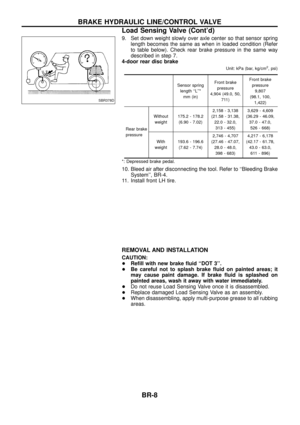
4. Remove front LH tire.
5. Connect tool to air bleeders on front LH brake caliper and rear LH or RH brake wheel cylinder.
6. Install front LH tire.
Before installing front LH tire, con®rm the tool is not touching
the front LH wheel.
7. Bleed air from Tool.
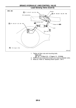
8. Raise front brake pressure to 4,904 kPa (49.0 bar, 50 kg/cm
2,
711 psi) and 9,807 kPa (98.1 bar, 100 kg/cm2, 1,422 psi) and
check rear brake pressure. Rear brake pressure: Refer to table on next page.
SBR287E
SBR822BA
SBR823BA
SBR377D
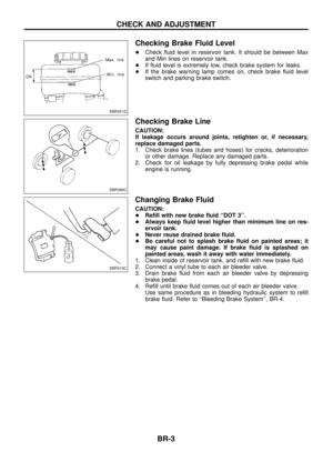
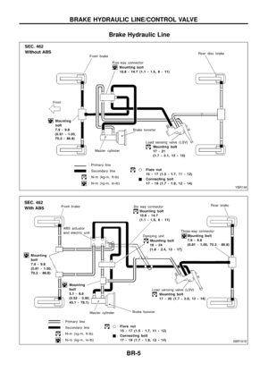
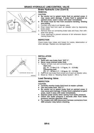
BRAKE HYDRAULIC LINE/CONTROL VALVE
Load Sensing Valve (Cont'd)
BR-7
Page 10 of 75
. Check rear brake pressure in the same way
described in step")
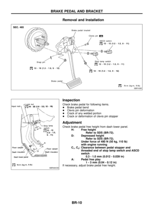
9. Set down weight slowly over axle center so that sensor springlength becomes the same as when in loaded condition (Refer
to table below). Check rear brake pressure in the same way
described in step 7.
4-door rear disc brake
Unit: kPa (bar, kg/cm2, psi)
Sensor spring
length ``L''* mm (in) Front brake
pressure
4,904 (49.0, 50, 711) Front brake
pressure 9,807
(98.1, 100, 1,422)
Rear brake
pressure Without
weight 175.2 - 178.2
(6.90 - 7.02) 2,158 - 3,138
(21.58 - 31.38, 22.0 - 32.0,313 - 455) 3,629 - 4,609
(36.29 - 46.09, 37.0 - 47.0,526 - 668)
With
weight 193.6 - 196.6
(7.62 - 7.74) 2,746 - 4,707
(27.46 - 47.07, 28.0 - 48.0,398 - 683) 4,217 - 6,178
(42.17 - 61.78, 43.0 - 63.0,611 - 896)
*: Depressed brake pedal.
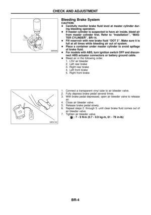
10. Bleed air after disconnecting the tool. Refer to ``Bleeding Brake System'', BR-4.
11. Install front LH tire.
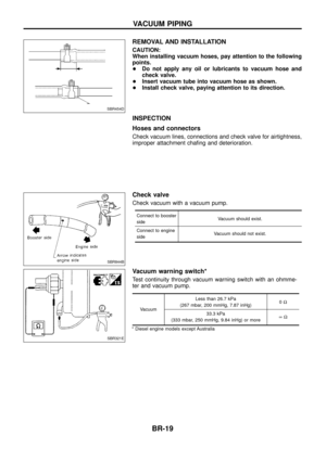
REMOVAL AND INSTALLATION
CAUTION:
+ Re®ll with new brake ¯uid ``DOT 3''.
+ Be careful not to splash brake ¯uid on painted areas; it
may cause paint damage. If brake ¯uid is splashed on
painted areas, wash it away with water immediately.
+ Do not reuse Load Sensing Valve once it is disassembled.
+ Replace damaged Load Sensing Valve as an assembly.
+ When disassembling, apply multi-purpose grease to all rubbing
areas.
SBR378D
BRAKE HYDRAULIC LINE/CONTROL VALVE
Load Sensing Valve (Cont'd)
BR-8
Page 11 of 75
1. Tighten all ¯are nuts and mounting bolts.Flare nut:
:15-17N zm (1.5 - 1.7 kg-m, 11 - 12 ft-lb)
2. Re®ll until new brake ¯uid comes out of each air bleeder valve.
3. Bleed air. Refer to ``Bleeding Brake System'', BR-4.
SBR162E
BRAKE HYDRAULIC LINE/CONTROL VALVE
Load Sensing Valve (Cont'd)
BR-9
Page 12 of 75
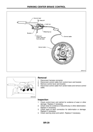
Removal and Installation
Inspection
Check brake pedal for following items.
+Brake pedal bend
+ Clevis pin deformation
+ Crack of any welded portion
+ Crack or deformation of clevis pin stopper
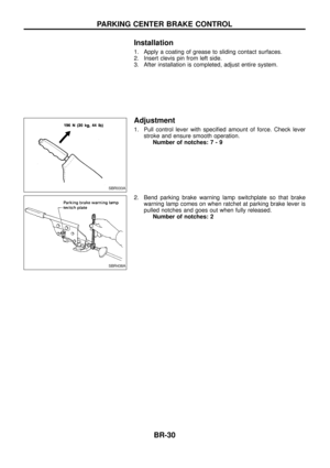
Adjustment
Check brake pedal free height from dash lower panel.
H: Free height Refer to SDS (BR-72).
D: Depressed height Refer to SDS (BR-72).
Under force of 490 N (50 kg, 110 lb)
with engine running
C
1,C2: Clearance between pedal stopper and threaded end of stop lamp switch and ASCD
switch 0.3 - 1.0 mm (0.012 - 0.039 in)
A: Pedal free play 1-3mm(0.04 - 0.12 in)
If necessary, adjust brake pedal free height.
SBR163E
SBR463CB
BRAKE PEDAL AND BRACKET
BR-10
Page 13 of 75
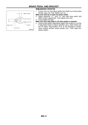
1. Loosen lock nut and adjust pedal free height by turning brakebooster input rod. Then tighten lock nut.
Make sure that tip of input rod stays inside.
2. Adjust clearance ``C
1'' and ``C2'' with stop lamp switch and
ASCD switch respectively. Then tighten lock nuts.
3. Check pedal free play.
Make sure that stop lamp is off when pedal is released.
4. Check brake pedal's depressed height while engine is running. If depressed height is below speci®ed value, check brake sys-
tem for leaks, accumulation of air or any damage to compo-
nents (master cylinder, wheel cylinder, etc.). Then make nec-
essary repairs.
SBR824B
BRAKE PEDAL AND BRACKET
Adjustment (Cont'd)
BR-11
Page 14 of 75
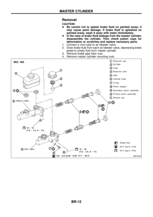
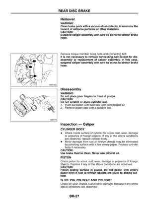
Removal
CAUTION:
+Be careful not to splash brake ¯uid on painted areas; it
may cause paint damage. If brake ¯uid is splashed on
painted areas, wash it away with water immediately.
+ In the case of brake ¯uid leakage from the master cylinder,
disassemble the cylinder. Then check piston cups for
deformation or scratches and replace necessary parts.
1. Connect a vinyl tube to air bleeder valve.
2. Drain brake ¯uid from each air bleeder valve, depressing brake pedal to empty ¯uid from master cylinder.
3. Remove brake pipe ¯are nuts.
4. Remove master cylinder mounting nuts.
SBR164E
MASTER CYLINDER
BR-12
Page 15 of 75
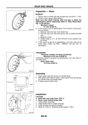
Disassembly
1. Bend claws of stopper cap outward.
2. Remove piston stopper while piston is pushed into cylinder(Models with ABS only).
3. Remove piston assemblies.
If it is difficult to remove secondary piston assembly, gradually
apply compressed air through ¯uid outlet.
4. Draw out reservoir tank.
Inspection
Check master cylinder inner wall for pin holes or scratches.
Replace if damaged.
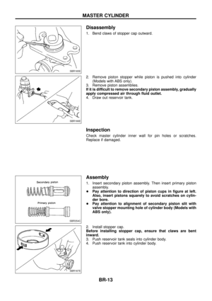
Assembly
1. Insert secondary piston assembly. Then insert primary piston assembly.
+ Pay attention to direction of piston cups in ®gure at left.
Also, insert pistons squarely to avoid scratches on cylin-
der bore.
+ Pay attention to alignment of secondary piston slit with
valve stopper mounting hole of cylinder body (Models with
ABS only).
2. Install stopper cap.
Before installing stopper cap, ensure that claws are bent
inward.
3. Push reservoir tank seals into cylinder body.
4. Push reservoir tank into cylinder body.
SBR165E
SBR166E
SBR354C
SBR167E
MASTER CYLINDER
BR-13
Page 16 of 75
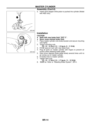
5. Install valve stopper while piston is pushed into cylinder (Modelwith ABS only).
Installation
CAUTION:
+Re®ll with new brake ¯uid ``DOT 3''.
+ Never reuse drained brake ¯uid.
1. Place master cylinder onto brake booster and secure mounting nuts lightly.
2. Torque mounting nuts.
:12-15N zm (1.2 - 1.5 kg-m ,9-11ft-lb)
3. Fill up reservoir tank with new brake ¯uid.
4. Plug all ports on master cylinder with ®ngers to prevent air suction while releasing brake pedal.
5. Have driver depress brake pedal slowly several times until no air comes out of master cylinder.
6. Fit brake lines to master cylinder.
7. Tighten ¯are nuts.
:15-17N zm (1.5 - 1.7 kg-m, 11 - 12 ft-lb)
8. Bleed air. Refer to ``Bleeding Brake System'', BR-4.
SBR168E
SBR169E
MASTER CYLINDER
Assembly (Cont'd)
BR-14

2. Re®ll until new brake ¯uid comes out of each air bleeder valve.
3. Bleed air. Refer to ``Bleedin")


.
3. Remove piston assemblies.
If it is difficult to remove seconda")
.
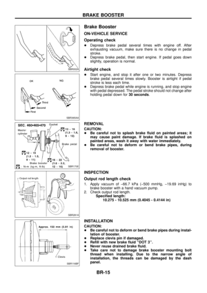
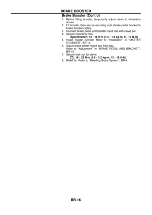
Installation
CAUTION:
+Re®ll with new brake ¯uid ``DOT 3.
+ Never reuse drained brake ¯uid.
1. Place master cyl")