Page 25 of 75

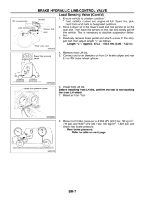
Removal
WARNING:
Clean brake pads with a vacuum dust collector to minimize the
hazard of airborne particles or other materials.
CAUTION:
Suspend caliper assembly with wire so as not to stretch brake
hose.
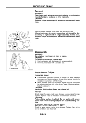
Remove torque member ®xing bolts and connecting bolt.
It is not necessary to remove connecting bolt except for dis-
assembly or replacement of caliper assembly. In this case,
suspend caliper assembly with wire so as not to stretch brake
hose.
Disassembly
WARNING:
Do not place your ®ngers in front of piston.
CAUTION:
Do not scratch or score cylinder wall.
1. Push out piston with dust seal with compressed air.
2. Remove piston seal with a suitable tool.
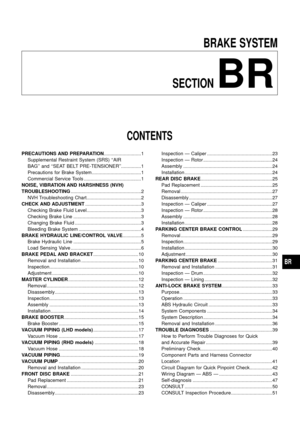
Inspection Ð Caliper
CYLINDER BODY
+Check inside surface of cylinder for score, rust, wear, damage
or presence of foreign objects. If any of the above conditions
are observed, replace cylinder body.
+ Minor damage from rust or foreign objects may be eliminated
by polishing surface with a ®ne emery paper. Replace cylinder
body if necessary.
CAUTION:
Use brake ¯uid to clean. Never use mineral oil.
PISTON
Check piston for score, rust, wear, damage or presence of foreign
objects. Replace if any of the above conditions are observed.
CAUTION:
Piston sliding surface is plated. Do not polish with emery
paper even if rust or foreign objects are stuck to sliding sur-
face.
SLIDE PIN, PIN BOLT AND PIN BOOT
Check for wear, cracks, rust or other damage. Replace if any of the
above conditions are observed.
SBR174E
SBR085A
FRONT DISC BRAKE
BR-23
Page 26 of 75
.
2. Check runout using a dial indicator.
Make sure that wheel bearing axial end play is within the
speci®c")
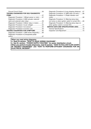
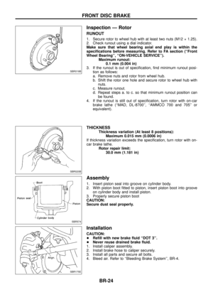
Inspection Ð Rotor
RUNOUT
1. Secure rotor to wheel hub with at least two nuts (M12 ý 1.25).
2. Check runout using a dial indicator.
Make sure that wheel bearing axial end play is within the
speci®cations before measuring. Refer to FA section (``Front
Wheel Bearing'', ``ON-VEHICLE SERVICE'').Maximum runout:0.1 mm (0.004 in)
3. If the runout is out of speci®cation, ®nd minimum runout posi- tion as follows:
a. Remove nuts and rotor from wheel hub.
b. Shift the rotor one hole and secure rotor to wheel hub withnuts.
c. Measure runout.
d. Repeat steps a. to c. so that minimum runout position can be found.
4. If the runout is still out of speci®cation, turn rotor with on-car brake lathe (``MAD, DL-8700'', ``AMMCO 700 and 705'' or
equivalent).
THICKNESS
Thickness variation (At least 8 positions): Maximum 0.015 mm (0.0006 in)
If thickness variation exceeds the speci®cation, turn rotor with on-
car brake lathe. Rotor repair limit:30.0 mm (1.181 in)
Assembly
1. Insert piston seal into groove on cylinder body.
2. With piston boot ®tted to piston, insert piston boot into grooveon cylinder body and install piston.
3. Properly secure piston boot
CAUTION:
Secure dust seal properly.
Installation
CAUTION:
+ Re®ll with new brake ¯uid ``DOT 3''.
+ Never reuse drained brake ¯uid.
1. Install caliper assembly.
2. Install brake hose to caliper securely.
3. Install all parts and secure all bolts.
4. Bleed air. Refer to ``Bleeding Brake System'', BR-4.
SBR019B
SBR020B
SBR574
SBR175E
FRONT DISC BRAKE
BR-24
Page 27 of 75

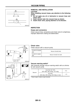
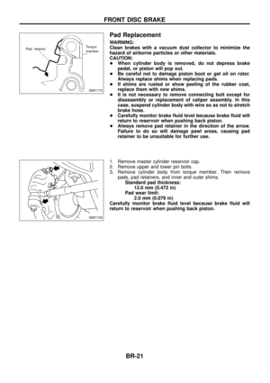
Pad Replacement
WARNING:
Clean brakes with a vacuum dust collector to minimize the
hazard of airborne particles or other materials.
CAUTION:
+When cylinder body is open, do not depress brake pedal,
or piston will pop out.
+ Be careful not to damage piston boot or get oil on rotor.
Always replace shims when replacing pads.
+ If shims are rusted or show peeling of the rubber coat,
replace them with new shims.
+ It is not necessary to remove connecting bolt except for
disassembly or replacement of caliper assembly. In this
case, suspend cylinder body with wire so as not to stretch
brake hose.
+ Carefully monitor brake ¯uid level because brake ¯uid will
return to reservoir when pushing back piston.
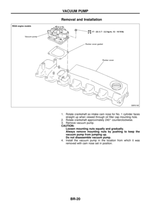
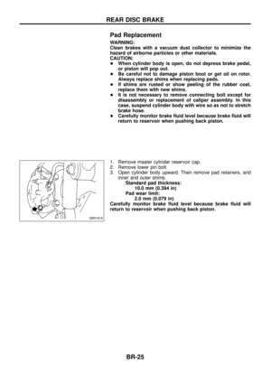
1. Remove master cylinder reservoir cap.
2. Remove lower pin bolt.
3. Open cylinder body upward. Then remove pad retainers, and inner and outer shims.Standard pad thickness: 10.0 mm (0.394 in)
Pad wear limit: 2.0 mm (0.079 in)
Carefully monitor brake ¯uid level because brake ¯uid will
return to reservoir when pushing back piston.
SBR181E
REAR DISC BRAKE
BR-25
Page 28 of 75
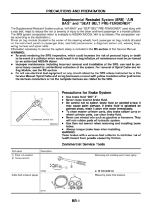
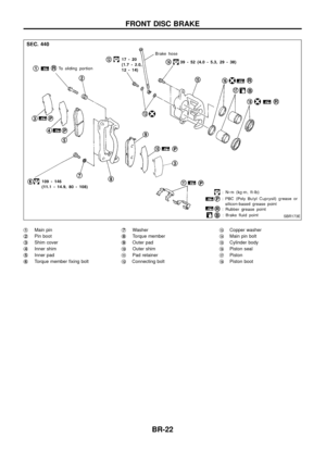
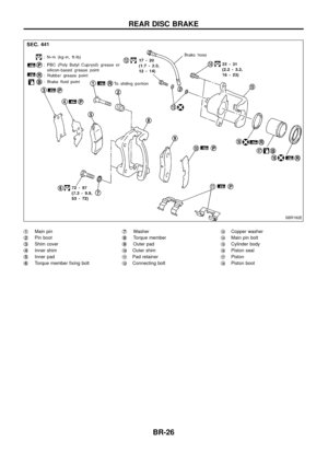
j1Main pin
j
2Pin boot
j
3Shim cover
j
4Inner shim
j
5Inner pad
j
6Torque member ®xing bolt j
7Washer
j
8Torque member
j
9Outer pad
j
10Outer shim
j
11Pad retainer
j
12Connecting bolt j
13Copper washer
j
14Main pin bolt
j
15Cylinder body
j
16Piston seal
j
17Piston
j
18Piston boot
SBR182E
REAR DISC BRAKE
BR-26
Page 29 of 75

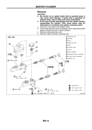
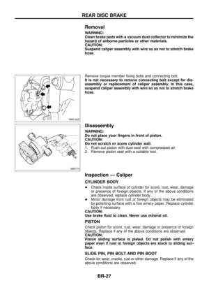
Removal
WARNING:
Clean brake pads with a vacuum dust collector to minimize the
hazard of airborne particles or other materials.
CAUTION:
Suspend caliper assembly with wire so as not to stretch brake
hose.
Remove torque member ®xing bolts and connecting bolt.
It is not necessary to remove connecting bolt except for dis-
assembly or replacement of caliper assembly. In this case,
suspend caliper assembly with wire so as not to stretch brake
hose.
Disassembly
WARNING:
Do not place your ®ngers in front of piston.
CAUTION:
Do not scratch or score cylinder wall.
1. Push out piston with dust seal with compressed air.
2. Remove piston seal with a suitable tool.
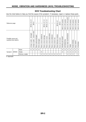
Inspection Ð Caliper
CYLINDER BODY
+Check inside surface of cylinder for score, rust, wear, damage
or presence of foreign objects. If any of the above conditions
are observed, replace cylinder body.
+ Minor damage from rust or foreign objects may be eliminated
by polishing surface with a ®ne emery paper. Replace cylinder
body if necessary.
CAUTION:
Use brake ¯uid to clean. Never use mineral oil.
PISTON
Check piston for score, rust, wear, damage or presence of foreign
objects. Replace if any of the above conditions are observed.
CAUTION:
Piston sliding surface is plated. Do not polish with emery
paper even if rust or foreign objects are stuck to sliding sur-
face.
SLIDE PIN, PIN BOLT AND PIN BOOT
Check for wear, cracks, rust or other damage. Replace if any of the
above conditions are observed.
SBR183E
SBR772
REAR DISC BRAKE
BR-27
Page 30 of 75
.
2. Check runout using a dial indicator.
Make sure that wheel bearing axial end play is within the
speci®c")
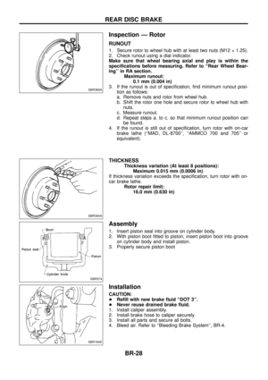
Inspection Ð Rotor
RUNOUT
1. Secure rotor to wheel hub with at least two nuts (M12 ý 1.25).
2. Check runout using a dial indicator.
Make sure that wheel bearing axial end play is within the
speci®cations before measuring. Refer to ``Rear Wheel Bear-
ing'' in RA section.Maximum runout:0.1 mm (0.004 in)
3. If the runout is out of speci®cation, ®nd minimum runout posi- tion as follows:
a. Remove nuts and rotor from wheel hub.
b. Shift the rotor one hole and secure rotor to wheel hub withnuts.
c. Measure runout.
d. Repeat steps a. to c. so that minimum runout position can be found.
4. If the runout is still out of speci®cation, turn rotor with on-car brake lathe (``MAD, DL-8700'', ``AMMCO 700 and 705'' or
equivalent).
THICKNESS
Thickness variation (At least 8 positions): Maximum 0.015 mm (0.0006 in)
If thickness variation exceeds the speci®cation, turn rotor with on-
car brake lathe. Rotor repair limit:16.0 mm (0.630 in)
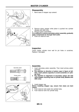
Assembly
1. Insert piston seal into groove on cylinder body.
2. With piston boot ®tted to piston, insert piston boot into grooveon cylinder body and install piston.
3. Properly secure piston boot
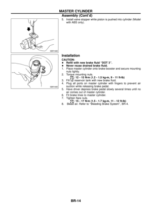
Installation
CAUTION:
+ Re®ll with new brake ¯uid ``DOT 3''.
+ Never reuse drained brake ¯uid.
1. Install caliper assembly.
2. Install brake hose to caliper securely.
3. Install all parts and secure all bolts.
4. Bleed air. Refer to ``Bleeding Brake System'', BR-4.
SBR389A
SBR390A
SBR574
SBR184E
REAR DISC BRAKE
BR-28
Page 31 of 75
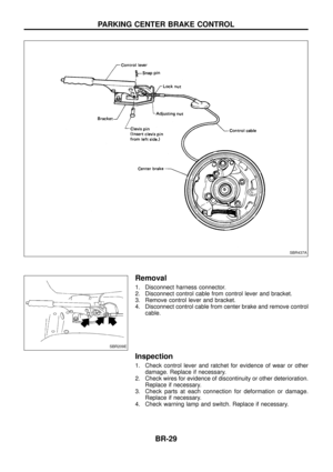
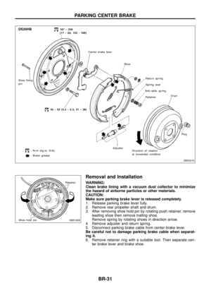
Removal
1. Disconnect harness connector.
2. Disconnect control cable from control lever and bracket.
3. Remove control lever and bracket.
4. Disconnect control cable from center brake and remove controlcable.
Inspection
1. Check control lever and ratchet for evidence of wear or otherdamage. Replace if necessary.
2. Check wires for evidence of discontinuity or other deterioration. Replace if necessary.
3. Check parts at each connection for deformation or damage. Replace if necessary.
4. Check warning lamp and switch. Replace if necessary.
SBR437A
SBR209E
PARKING CENTER BRAKE CONTROL
BR-29
Page 32 of 75
Installation
1. Apply a coating of grease to sliding contact surfaces.
2. Insert clevis pin from left side.
3. After installation is completed, adjust entire system.
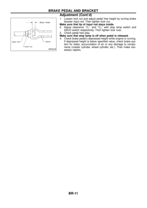
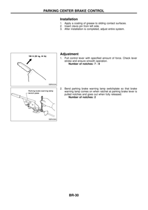
Adjustment
1. Pull control lever with speci®ed amount of force. Check leverstroke and ensure smooth operation.Number of notches :7-9
2. Bend parking brake warning lamp switchplate so that brake warning lamp comes on when ratchet at parking brake lever is
pulled notches and goes out when fully released.Number of notches: 2
SBR033A
SBR438A
PARKING CENTER BRAKE CONTROL
BR-30