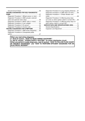
Page 57 of 75

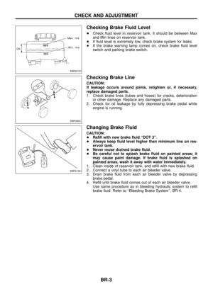
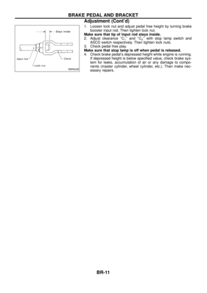
Wheel speed signal
(Almost the same speed a")
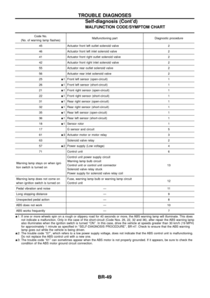
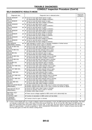
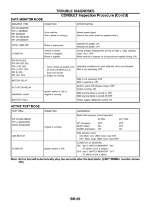
DATA MONITOR MODE
MONITOR ITEM CONDITION SPECIFICATION
FR RH SENSOR
FR LH SENSOR
RR SENSOR
RR RH SENSOR
RR LH SENSORDrive vehicle.
(Each wheel is rotating.)
Wheel speed signal
(Almost the same speed as speedometer.)
STOP LAMP SW Brake is depressed. Depress the pedal: ON
Release the pedal: OFF
G-SWITCH Vehicle is driven.
Vehicle is stopped.
Brake is applied.During sudden braking while driving on high roads (asphalt
roads, etc.): OFF
While vehicle is stopped or during constant-speed driving: ON
FR RH IN SOL
FR RH OUT SOL
FR LH IN SOL
FR LH OUT SOL
RR IN SOL
RR OUT SOL 1. Drive vehicle at speeds over
30 km/h (19 MPH) for at
least one minute.
2. Engine is running. Operating conditions for each solenoid valve are indicated.
ABS is not operating: OFF
MOTOR RELAY ABS is not operating: OFF
ABS is operating: ON
ACTUATOR RELAY Ignition switch is ON or
engine is running.Ignition switch ON (Engine stops): OFF
Engine running: ON
WARNING LAMP ABS warning lamp is turned on: ON
ABS warning lamp is turned off: OFF
BATTERY VOLT Power supply voltage for control unit
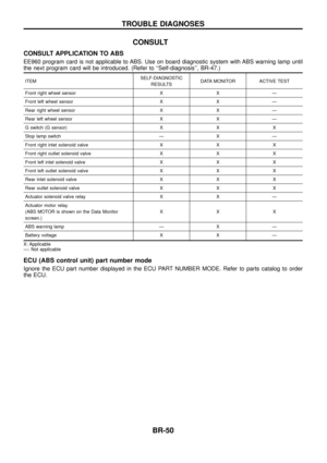
ACTIVE TEST MODE
TEST ITEM CONDITION JUDGEMENT
FR RH SOLENOID
FR LH SOLENOID
REAR SOLENOID Engine is running.Brake ¯uid pressure control operation
IN SOL OUT SOL
UP (Increase):
KEEP (Hold):
DOWN (Decrease): OFF
ON
ONOFF
OFF
ON
ABS MOTOR ABS actuator motor
ON: Motor runs (ABS motor relay ON)
OFF: Motor stops (ABS motor relay OFF)
G SWITCH Ignition switch is ON. G SWITCH (G SENSOR),
ON: Set G SWITCH MONITOR ``ON''
(G switch circuit is closed.)
OFF: Set G SWITCH MONITOR ``OFF'' (G switch circuit is open.)
Note: Active test will automatically stop ten seconds after the test starts. (LIMIT SIGNAL monitor shows ON.)
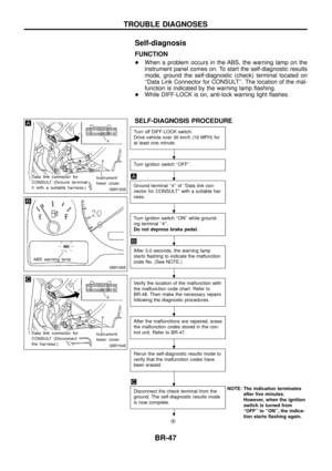
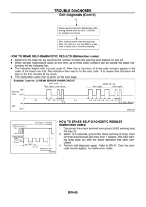
TROUBLE DIAGNOSES
CONSULT Inspection Procedure (Cont'd)
BR-55
Page 58 of 75
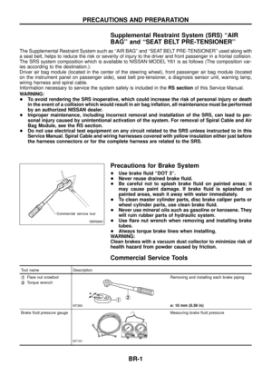
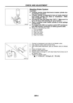
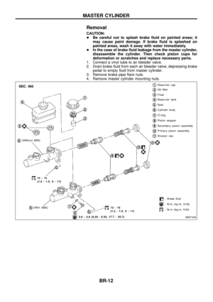
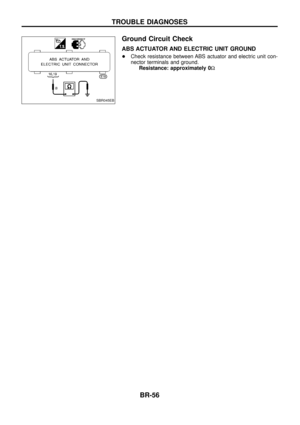
Ground Circuit Check
ABS ACTUATOR AND ELECTRIC UNIT GROUND
+Check resistance between ABS actuator and electric unit con-
nector terminals and ground.
Resistance: approximately 0 W
SBR045EB
TROUBLE DIAGNOSES
BR-56
Page 59 of 75

Malfunction code No. 21, 22, 25, 26, 31, 32, 35, 36 or 18
INSPECTION START
- ----------------------------------------------------------------------------")
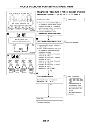
Diagnostic Procedure 1 (Wheel sensor or rotor)
Malfunction code No. 21, 22, 25, 26, 31, 32, 35, 36 or 18
INSPECTION START
- ---------------------------------------------------------------------------------------------------------------------------------------------------------------------------------------------------------------------------------------------------------------------------------------------------------------
1. Disconnect connectors from ABS actua- tor and electric unit and wheel sensor
of malfunction code No. Check termi-
nals for damage or loose connections.
Then reconnect connectors.
2. Carry out self-diagnosis again. Does warning lamp activate again?
Ye s
cNo Inspection end
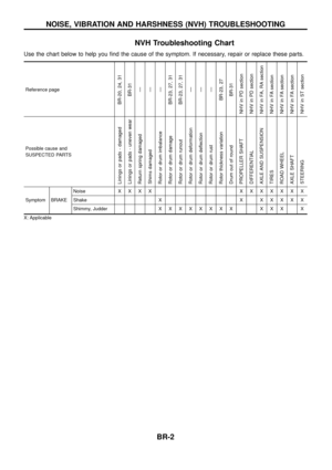
CHECK WHEEL SENSOR ELECTRICAL.
- ---------------------------------------------------------------------------------------------------------------------------------------------------------------------------------------------------------------------------------------------------------------------------------------------------------------
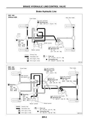
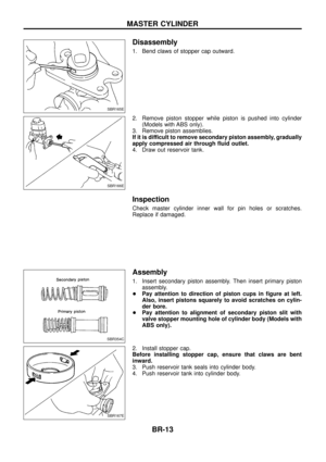
1. Disconnect ABS actuator and electric unit connector.
2. Check resistance between ABS actua- tor and electric unit connector
E18
(body side) terminals.
Code No. 21 or 22 (Front RH wheel)
Terminals j
4andj5
Code No. 25 or 26 (Front LH wheel)
Terminals j
6andj7
Code No. 31 or 32 (Rear RH wheel)
Terminals j
1andj2
Code No. 35 or 36 (Rear LH wheel)
Terminals j
8andj9
Resistance: 1.44 - 1.76 k
W
NG
cOK
jA(Go to next page.)
CHECK WHEEL SENSOR.
- ---------------------------------------------------------------------------------------------------------------------------------------------------------------------------------------------------------------------------------------------------------------------------------------------------------------
Check each sensor for resistance.
Resistance: 1.44 - 1.76 k W
NG
cOK
Check the following.
+Harness connectors
E18,E77,E62,C6,
C5
+Harness for open or
short between wheel
sensor connectors and
ABS actuator and elec-
tric unit
If NG, repair harness or
connectors.
REPLACE.
- ---------------------------------------------------------------------------------------------------------------------------------------------------------------------------------------------------------------------------------------------------------------------------------------------------------------
Replace wheel sensor.
SBR196E
SBR048EB
SBR197E
.
.
.
TROUBLE DIAGNOSES FOR SELF-DIAGNOSTIC ITEMS
BR-57
Page 60 of 75

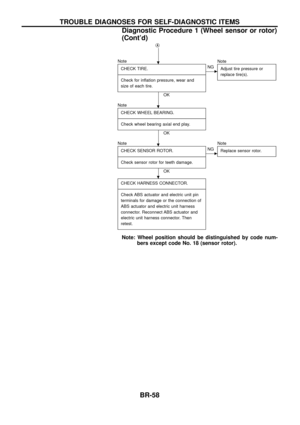
jA
NoteCHECK TIRE.
- ---------------------------------------------------------------------------------------------------------------------------------------------------------------------------------------------------------------------------------------------------------------------------------------------------------------
Check for in¯ation pressure, wear and
size of each tire.
OK
cNG Note
Adjust tire pressure or
replace tire(s).
NoteCHECK WHEEL BEARING.
- ---------------------------------------------------------------------------------------------------------------------------------------------------------------------------------------------------------------------------------------------------------------------------------------------------------------
Check wheel bearing axial end play.
OK
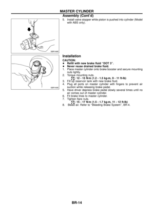
Note CHECK SENSOR ROTOR.
- ---------------------------------------------------------------------------------------------------------------------------------------------------------------------------------------------------------------------------------------------------------------------------------------------------------------
Check sensor rotor for teeth damage.
OK
cNG Note
Replace sensor rotor.
CHECK HARNESS CONNECTOR.
- ---------------------------------------------------------------------------------------------------------------------------------------------------------------------------------------------------------------------------------------------------------------------------------------------------------------
Check ABS actuator and electric unit pin
terminals for damage or the connection of
ABS actuator and electric unit harness
connector. Reconnect ABS actuator and
electric unit harness connector. Then
retest.
Note: Wheel position should be distinguished by code num- bers except code No. 18 (sensor rotor).
.
.
.
.
TROUBLE DIAGNOSES FOR SELF-DIAGNOSTIC ITEMS
Diagnostic Procedure 1 (Wheel sensor or rotor)
(Cont'd)
BR-58
Page 61 of 75

Malfunction code No. 41, 45, 55, 42, 46, 56, 63
CHECK FUSIBLE LINK.
- ----------------------------------------------------")
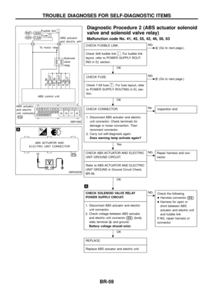
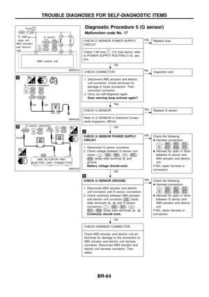
Diagnostic Procedure 2 (ABS actuator solenoid
valve and solenoid valve relay)
Malfunction code No. 41, 45, 55, 42, 46, 56, 63
CHECK FUSIBLE LINK.
- ---------------------------------------------------------------------------------------------------------------------------------------------------------------------------------------------------------------------------------------------------------------------------------------------------------------
Check 30A fusible link
i. For fusible link
layout, refer to POWER SUPPLY ROUT-
ING in EL section.
OK
cNG jA(Go to next page.)
CHECK FUSE.
- ---------------------------------------------------------------------------------------------------------------------------------------------------------------------------------------------------------------------------------------------------------------------------------------------------------------
Check 7.5A fuse
7. For fuse layout, refer
to POWER SUPPLY ROUTING in EL sec-
tion.
OK
cNG jB(Go to next page.)
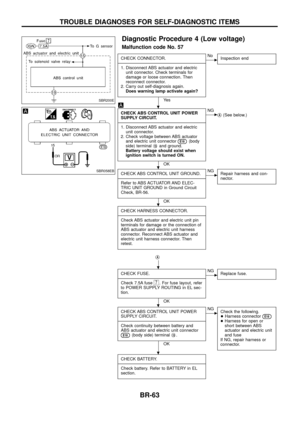
CHECK CONNECTOR.
- ---------------------------------------------------------------------------------------------------------------------------------------------------------------------------------------------------------------------------------------------------------------------------------------------------------------
1. Disconnect ABS actuator and electric unit connector. Check terminals for
damage or loose connection. Then
reconnect connector.
2. Carry out self-diagnosis again. Does warning lamp activate again?
Ye s
cNo Inspection end
CHECK ABS ACTUATOR AND ELECTRIC
UNIT GROUND CIRCUIT.
- ---------------------------------------------------------------------------------------------------------------------------------------------------------------------------------------------------------------------------------------------------------------------------------------------------------------
Refer to ABS ACTUATOR AND ELECTRIC
UNIT GROUND in Ground Circuit Check,
BR-56.
OK
cNG Repair harness and con-
nector.
CHECK SOLENOID VALVE RELAY
POWER SUPPLY CIRCUIT.
- ---------------------------------------------------------------------------------------------------------------------------------------------------------------------------------------------------------------------------------------------------------------------------------------------------------------
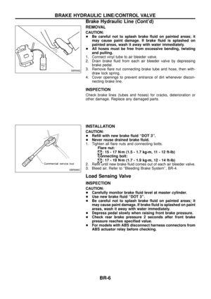
1. Disconnect ABS actuator and electric unit connector.
2. Check voltage between ABS actuator and electric unit connector
E18(body
side) terminal j
18and ground.
Battery voltage should exist.
OK
cNG Check the following.
+Harness connector
E18
+Harness for open or
short between ABS
actuator and electric unit
and fusible link
If NG, repair harness or
connector.
REPLACE.
- ---------------------------------------------------------------------------------------------------------------------------------------------------------------------------------------------------------------------------------------------------------------------------------------------------------------
Replace ABS actuator and electric unit.
SBR198E
SBR052EB
.
.
.
.
.
TROUBLE DIAGNOSES FOR SELF-DIAGNOSTIC ITEMS
BR-59
Page 62 of 75

jA
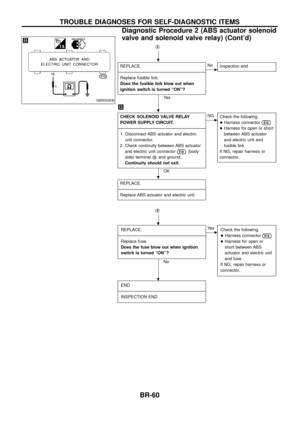
REPLACE.
- ---------------------------------------------------------------------------------------------------------------------------------------------------------------------------------------------------------------------------------------------------------------------------------------------------------------
Replace fusible link.
Does the fusible link blow out when
ignition switch is turned ``ON''?
Ye s
cNo Inspection end
CHECK SOLENOID VALVE RELAY
POWER SUPPLY CIRCUIT.
- ---------------------------------------------------------------------------------------------------------------------------------------------------------------------------------------------------------------------------------------------------------------------------------------------------------------
1. Disconnect ABS actuator and electric
unit connector.
2. Check continuity between ABS actuator and electric unit connector
E18(body
side) terminal j
18and ground.
Continuity should not exit.
OK
cNG Check the following.
+Harness connector
E18
+Harness for open or short
between ABS actuator
and electric unit and
fusible link
If NG, repair harness or
connector.
REPLACE.
- ---------------------------------------------------------------------------------------------------------------------------------------------------------------------------------------------------------------------------------------------------------------------------------------------------------------
Replace ABS actuator and electric unit.
jB
REPLACE.
- ---------------------------------------------------------------------------------------------------------------------------------------------------------------------------------------------------------------------------------------------------------------------------------------------------------------
Replace fuse.
Does the fuse blow out when ignition
switch is turned ``ON''?
No
cYe s Check the following.
+Harness connector
E18
+Harness for open or
short between ABS
actuator and electric unit
and fuse
If NG, repair harness or
connector.
END
- ---------------------------------------------------------------------------------------------------------------------------------------------------------------------------------------------------------------------------------------------------------------------------------------------------------------
INSPECTION END
SBR053EB
.
.
.
.
.
TROUBLE DIAGNOSES FOR SELF-DIAGNOSTIC ITEMS
Diagnostic Procedure 2 (ABS actuator solenoid
valve and solenoid valve relay) (Cont'd)
BR-60
Page 63 of 75

Malfunction code No. 61
CHECK FUSIBLE LINK.
- ------------------------------------------------------------------------------------------------------------")
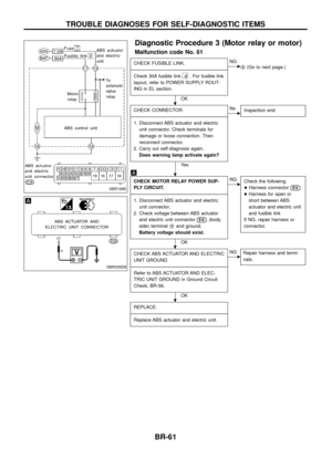
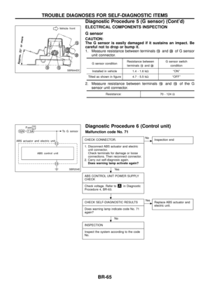
Diagnostic Procedure 3 (Motor relay or motor)
Malfunction code No. 61
CHECK FUSIBLE LINK.
- ---------------------------------------------------------------------------------------------------------------------------------------------------------------------------------------------------------------------------------------------------------------------------------------------------------------
Check 30A fusible link
d . For fusible link
layout, refer to POWER SUPPLY ROUT-
ING in EL section.
OK
cNG jA(Go to next page.)
CHECK CONNECTOR.
- ---------------------------------------------------------------------------------------------------------------------------------------------------------------------------------------------------------------------------------------------------------------------------------------------------------------
1. Disconnect ABS actuator and electric unit connector. Check terminals for
damage or loose connection. Then
reconnect connector.
2. Carry out self-diagnosis again. Does warning lamp activate again?
Ye s
cNo Inspection end
CHECK MOTOR RELAY POWER SUP-
PLY CIRCUIT.
- ---------------------------------------------------------------------------------------------------------------------------------------------------------------------------------------------------------------------------------------------------------------------------------------------------------------
1. Disconnect ABS actuator and electric unit connector.
2. Check voltage between ABS actuator and electric unit connector
E18(body
side) terminal j
17and ground.
Battery voltage should exist.
OK
cNG Check the following.
+Harness connector
E18
+Harness for open or
short between ABS
actuator and electric unit
and fusible link
If NG, repair harness or
connector.
CHECK ABS ACTUATOR AND ELECTRIC
UNIT GROUND.
- ---------------------------------------------------------------------------------------------------------------------------------------------------------------------------------------------------------------------------------------------------------------------------------------------------------------
Refer to ABS ACTUATOR AND ELEC-
TRIC UNIT GROUND in Ground Circuit
Check, BR-56.
OK
cNG Repair harness and termi-
nals.
REPLACE.
- ---------------------------------------------------------------------------------------------------------------------------------------------------------------------------------------------------------------------------------------------------------------------------------------------------------------
Replace ABS actuator and electric unit.
SBR199E
SBR055EB
.
.
.
.
TROUBLE DIAGNOSES FOR SELF-DIAGNOSTIC ITEMS
BR-61
Page 64 of 75

jA
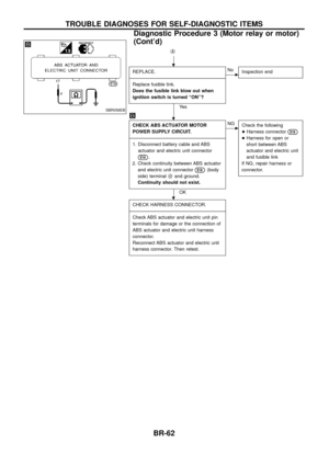
REPLACE.
- ---------------------------------------------------------------------------------------------------------------------------------------------------------------------------------------------------------------------------------------------------------------------------------------------------------------
Replace fusible link.
Does the fusible link blow out when
ignition switch is turned ``ON''?
Ye s
cNo Inspection end
CHECK ABS ACTUATOR MOTOR
POWER SUPPLY CIRCUIT.
- ---------------------------------------------------------------------------------------------------------------------------------------------------------------------------------------------------------------------------------------------------------------------------------------------------------------
1. Disconnect battery cable and ABS actuator and electric unit connector
E18.
2. Check continuity between ABS actuator and electric unit connector
E18(body
side) terminal j
17and ground.
Continuity should not exist.
OK
cNG Check the following
+Harness connector
E18
+Harness for open or
short between ABS
actuator and electric unit
and fusible link
If NG, repair harness or
connector.
CHECK HARNESS CONNECTOR.
- ---------------------------------------------------------------------------------------------------------------------------------------------------------------------------------------------------------------------------------------------------------------------------------------------------------------
Check ABS actuator and electric unit pin
terminals for damage or the connection of
ABS actuator and electric unit harness
connector.
Reconnect ABS actuator and electric unit
harness connector. Then retest.
SBR056EB
.
.
.
TROUBLE DIAGNOSES FOR SELF-DIAGNOSTIC ITEMS
Diagnostic Procedure 3 (Motor relay or motor)
(Cont'd)
BR-62