Page 17 of 75

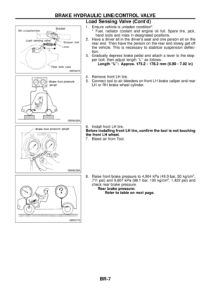
Brake Booster
ON-VEHICLE SERVICE
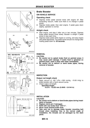
Operating check
+Depress brake pedal several times with engine off. After
exhausting vacuum, make sure there is no change in pedal
stroke.
+ Depress brake pedal, then start engine. If pedal goes down
slightly, operation is normal.
Airtight check
+Start engine, and stop it after one or two minutes. Depress
brake pedal several times slowly. Booster is airtight if pedal
stroke is less each time.
+ Depress brake pedal while engine is running, and stop engine
with pedal depressed. The pedal stroke should not change after
holding pedal down for 30 seconds.
REMOVAL
CAUTION:
+Be careful not to splash brake ¯uid on painted areas; it
may cause paint damage. If brake ¯uid is splashed on
painted areas, wash it away with water immediately.
+ Be careful not to deform or bend brake pipes, during
removal of booster.
INSPECTION
Output rod length check
1. Apply vacuum of þ66.7 kPa (þ500 mmHg, þ19.69 inHg) to
brake booster with a hand vacuum pump.
2. Check output rod length. Speci®ed length:10.275 - 10.525 mm (0.4045 - 0.4144 in)
INSTALLATION
CAUTION:
+Be careful not to deform or bend brake pipes during instal-
lation of booster.
+ Replace clevis pin if damaged.
+ Re®ll with new brake ¯uid ``DOT 3''.
+ Never reuse drained brake ¯uid.
+ Take care not to damage brake booster mounting bolt
thread when installing. Due to the narrow angle of
installation, the threads can be damaged by the dash
panel.
SBR002A
SBR365AA
SBR170E
SBR281A
SBR116BF
BRAKE BOOSTER
BR-15
Page 18 of 75
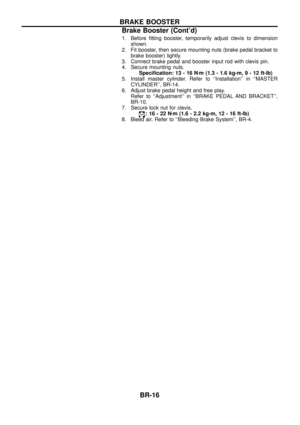
1. Before ®tting booster, temporarily adjust clevis to dimensionshown.
2. Fit booster, then secure mounting nuts (brake pedal bracket to brake booster) lightly.
3. Connect brake pedal and booster input rod with clevis pin.
4. Secure mounting nuts. Speci®cation: 13 - 16 N zm (1.3 - 1.6 kg-m ,9-12ft-lb)
5. Install master cylinder. Refer to ``Installation'' in ``MASTER CYLINDER'', BR-14.
6. Adjust brake pedal height and free play. Refer to ``Adjustment'' in ``BRAKE PEDAL AND BRACKET'',
BR-10.
7. Secure lock nut for clevis.
:16-22N zm (1.6 - 2.2 kg-m, 12 - 16 ft-lb)
8. Bleed air. Refer to ``Bleeding Brake System'', BR-4.
BRAKE BOOSTER
Brake Booster (Cont'd)
BR-16
Page 19 of 75
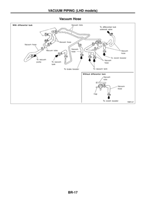
Vacuum Hose
YBR147
VACUUM PIPING (LHD models)
BR-17
Page 20 of 75
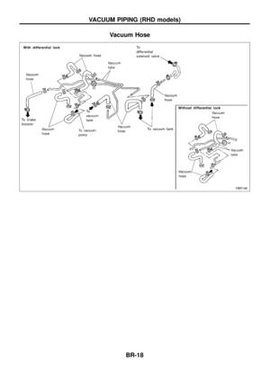
Vacuum Hose
YBR148
VACUUM PIPING (RHD models)
BR-18
Page 21 of 75
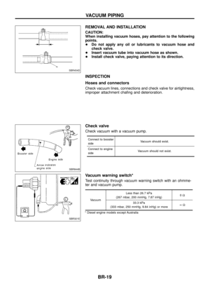
REMOVAL AND INSTALLATION
CAUTION:
When installing vacuum hoses, pay attention to the following
points.
+Do not apply any oil or lubricants to vacuum hose and
check valve.
+ Insert vacuum tube into vacuum hose as shown.
+ Install check valve, paying attention to its direction.
INSPECTION
Hoses and connectors
Check vacuum lines, connections and check valve for airtightness,
improper attachment cha®ng and deterioration.
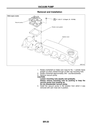
Check valve
Check vacuum with a vacuum pump.
Connect to booster
side Vacuum should exist.
Connect to engine
side Vacuum should not exist.
Vacuum warning switch*
Test continuity through vacuum warning switch with an ohmme-
ter and vacuum pump.
VacuumLess than 26.7 kPa
(267 mbar, 200 mmHg, 7.87 inHg) 0
W
33.3 kPa
(333 mbar, 250 mmHg, 9.84 inHg) or more ¥W
* Diesel engine models except Australia
SBR454D
SBR844B
SBR321E
VACUUM PIPING
BR-19
Page 22 of 75
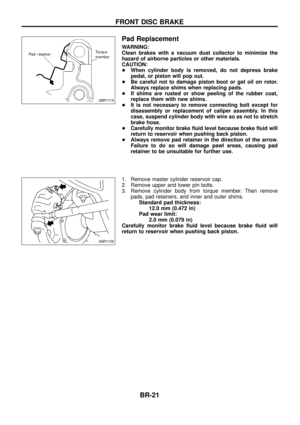
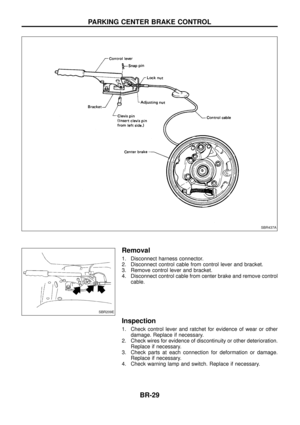
Removal and Installation
1. Rotate crankshaft so intake cam nose for No. 1 cylinder facesstraight up when viewed through oil ®ller cap mounting hole.
2. Rotate crankshaft approximately 240É counterclockwise.
3. Remove vacuum pump.
CAUTION: Loosen mounting nuts equally and gradually.
Always remove mounting nuts by pushing to keep the
vacuum pump from jumping up.
Do not disassemble vacuum pump.
4. Install the vacuum pump in the location from which it was removed with cam nose set in position.
SBR319E
RD28 engine models
Vacuum pump
17 - 22 (1.7 - 2.2 kg-m, 12 - 16 ft-lb)
Rocker cover gasket
Rocker cover
VACUUM PUMP
BR-20
Page 23 of 75

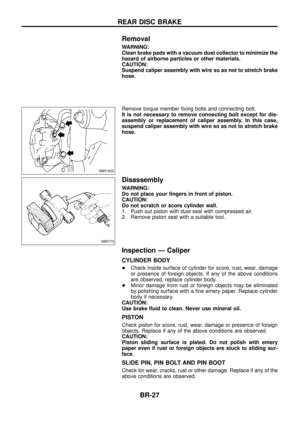
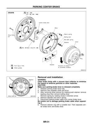
Pad Replacement
WARNING:
Clean brakes with a vacuum dust collector to minimize the
hazard of airborne particles or other materials.
CAUTION:
+When cylinder body is removed, do not depress brake
pedal, or piston will pop out.
+ Be careful not to damage piston boot or get oil on rotor.
Always replace shims when replacing pads.
+ If shims are rusted or show peeling of the rubber coat,
replace them with new shims.
+ It is not necessary to remove connecting bolt except for
disassembly or replacement of caliper assembly. In this
case, suspend cylinder body with wire so as not to stretch
brake hose.
+ Carefully monitor brake ¯uid level because brake ¯uid will
return to reservoir when pushing back piston.
+ Always remove pad retainer in the direction of the arrow.
Failure to do so will damage pawl areas, causing pad
retainer to be unsuitable for further use.
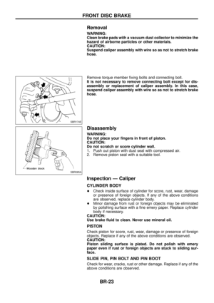
1. Remove master cylinder reservoir cap.
2. Remove upper and lower pin bolts.
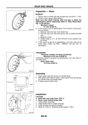
3. Remove cylinder body from torque member. Then remove pads, pad retainers, and inner and outer shims.Standard pad thickness: 12.0 mm (0.472 in)
Pad wear limit: 2.0 mm (0.079 in)
Carefully monitor brake ¯uid level because brake ¯uid will
return to reservoir when pushing back piston.
SBR171E
SBR172E
FRONT DISC BRAKE
BR-21
Page 24 of 75
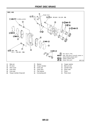
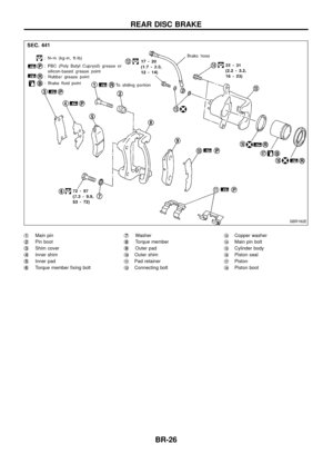
j1Main pin
j
2Pin boot
j
3Shim cover
j
4Inner shim
j
5Inner pad
j
6Torque member ®xing bolt j
7Washer
j
8Torque member
j
9Outer pad
j
10Outer shim
j
11Pad retainer
j
12Connecting bolt j
13Copper washer
j
14Main pin bolt
j
15Cylinder body
j
16Piston seal
j
17Piston
j
18Piston boot
SBR173E
FRONT DISC BRAKE
BR-22
 lightly.
3. Connect brake pedal and booster inp")

BR-17")

BR-18")


