1998 NISSAN PATROL sensor
[x] Cancel search: sensorPage 2 of 75
Ground Circuit Check ................................................56
TROUBLE DIAGNOSES FOR SELF-DIAGNOSTIC
ITEMS ........................................................................\
.....57
Diagnostic Procedure 1 (Wheel sensor or rotor) ......57
Diagnostic Procedure 2 (ABS actuator solenoid
valve and solenoid valve relay) .................................59
Diagnostic Procedure 3 (Motor relay or motor).........61
Diagnostic Procedure 4 (Low voltage) ......................63
Diagnostic Procedure 5 (G sensor) ...........................64
Diagnostic Procedure 6 (Control unit) .......................65
TROUBLE DIAGNOSES FOR SYMPTOMS .................66
Diagnostic Procedure 7 (ABS works frequently.) ......66
Diagnostic Procedure 8 (Unexpected pedal
action) ........................................................................\
67 Diagnostic Procedure 9 (Long stopping distance) ....67
Diagnostic Procedure 10 (ABS does not work.) .......68
Diagnostic Procedure 11 (Pedal vibration and
noise) ........................................................................\
.68
Diagnostic Procedure 12 (Warning lamp does
not come on when ignition switch is turned ON.) .....69
Diagnostic Procedure 13 (Warning lamp stays on
when ignition switch is turned ON.)...........................71
SERVICE DATA AND SPECIFICATIONS (SDS) ..........72
General Speci®cations ...............................................72
Inspection and Adjustment ........................................73
When you read wiring diagrams:
+ Read GI section, ``HOW TO READ WIRING DIAGRAMS''.
+ See EL section, ``POWER SUPPLY ROUTING'' for power distribution circuit.
When you perform trouble diagnoses, read GI section, ``HOW TO FOLLOW FLOW CHART
IN TROUBLE DIAGNOSES'' and ``HOW TO PERFORM EFFICIENT DIAGNOSIS FOR AN
ELECTRICAL INCIDENT''.
Page 3 of 75
Supplemental Restraint System (SRS) ``AIR
BAG'' and ``SEAT BELT PRE-TENSIONER''
The Supplemental Restraint System such as ``AIR BAG'' and ``SEAT BELT PRE-TENSIONER'' used along with
a seat belt, helps to reduce the risk or severity of injury to the driver and front passenger in a frontal collision.
The SRS system composition which is available to NISSAN MODEL Y61 is as follows (The composition var-
ies according to the destination.):
Driver air bag module (located in the center of the steering wheel), front passenger air bag module (located
on the instrument panel on passenger side), seat belt pre-tensioner, a diagnosis sensor unit, warning lamp,
wiring harness and spiral cable.
Information necessary to service the system safely is included in theRS sectionof this Service Manual.
WARNING:
+ To avoid rendering the SRS inoperative, which could increase the risk of personal injury or death
in the event of a collision which would result in air bag in¯ation, all maintenance must be performed
by an authorized NISSAN dealer.
+ Improper maintenance, including incorrect removal and installation of the SRS, can lead to per-
sonal injury caused by unintentional activation of the system. For removal of Spiral Cable and Air
Bag Module, see the RS section.
+ Do not use electrical test equipment on any circuit related to the SRS unless instructed to in this
Service Manual. Spiral Cable and wiring harnesses covered with yellow insulation either just before
the harness connectors or for the complete harness are related to the SRS.
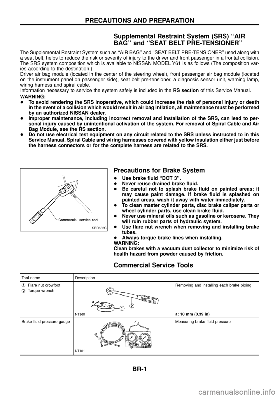
Precautions for Brake System
+Use brake ¯uid ``DOT 3''.
+ Never reuse drained brake ¯uid.
+ Be careful not to splash brake ¯uid on painted areas; it
may cause paint damage. If brake ¯uid is splashed on
painted areas, wash it away with water immediately.
+ To clean master cylinder parts, disc brake caliper parts or
wheel cylinder parts, use clean brake ¯uid.
+ Never use mineral oils such as gasoline or kerosene. They
will ruin rubber parts of hydraulic system.
+ Use ¯are nut wrench when removing and installing brake
tubes.
+ Always torque brake lines when installing.
WARNING:
Clean brakes with a vacuum dust collector to minimize risk of
health hazard from powder caused by friction.
Commercial Service Tools
Tool name Description
j
1Flare nut crowfoot
j
2Torque wrench
NT360
Removing and installing each brake piping
a: 10 mm (0.39 in)
Brake ¯uid pressure gauge
NT151
Measuring brake ¯uid pressure
SBR686C
PRECAUTIONS AND PREPARATION
BR-1
Page 10 of 75
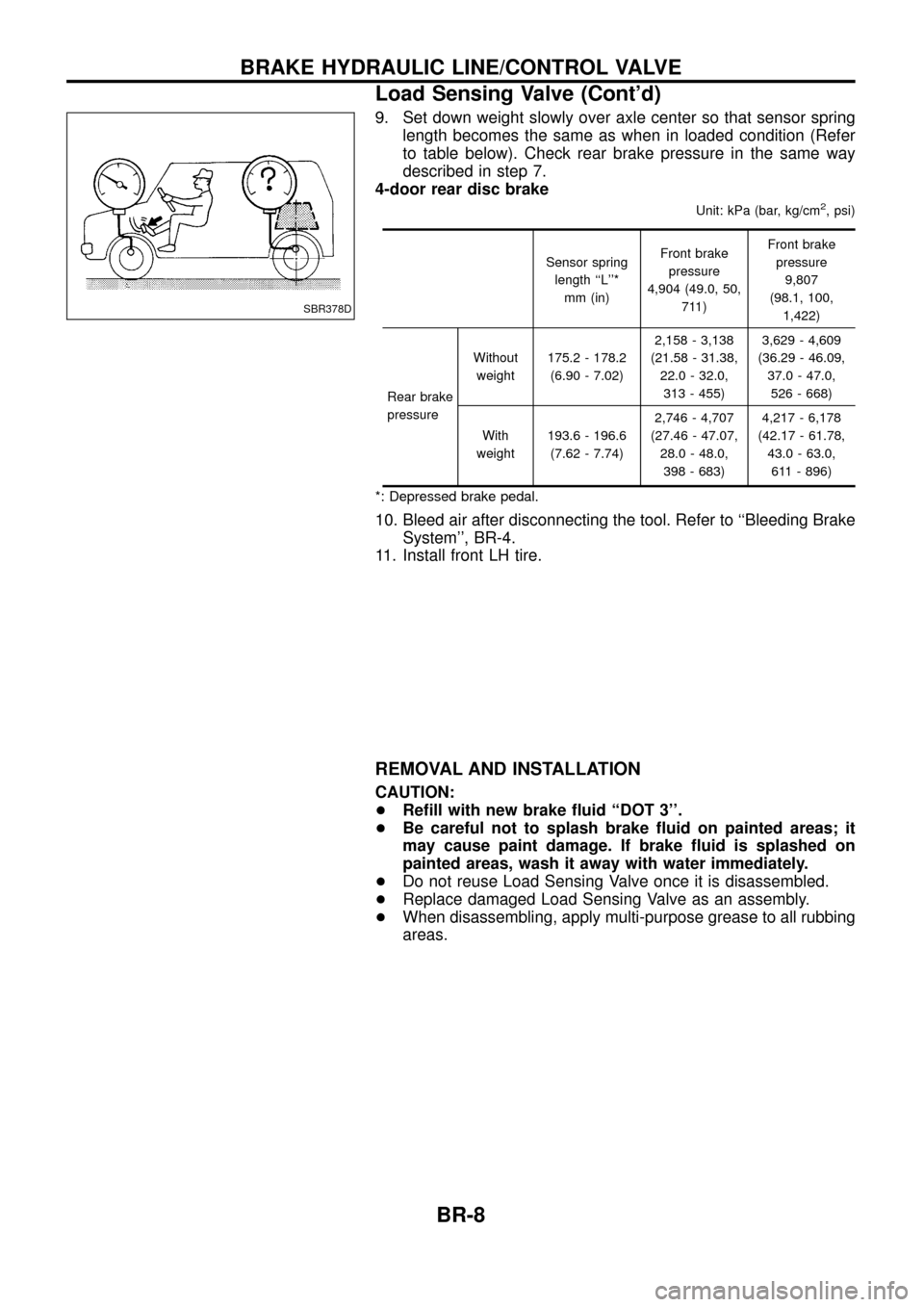
9. Set down weight slowly over axle center so that sensor springlength becomes the same as when in loaded condition (Refer
to table below). Check rear brake pressure in the same way
described in step 7.
4-door rear disc brake
Unit: kPa (bar, kg/cm2, psi)
Sensor spring
length ``L''* mm (in) Front brake
pressure
4,904 (49.0, 50, 711) Front brake
pressure 9,807
(98.1, 100, 1,422)
Rear brake
pressure Without
weight 175.2 - 178.2
(6.90 - 7.02) 2,158 - 3,138
(21.58 - 31.38, 22.0 - 32.0,313 - 455) 3,629 - 4,609
(36.29 - 46.09, 37.0 - 47.0,526 - 668)
With
weight 193.6 - 196.6
(7.62 - 7.74) 2,746 - 4,707
(27.46 - 47.07, 28.0 - 48.0,398 - 683) 4,217 - 6,178
(42.17 - 61.78, 43.0 - 63.0,611 - 896)
*: Depressed brake pedal.
10. Bleed air after disconnecting the tool. Refer to ``Bleeding Brake System'', BR-4.
11. Install front LH tire.
REMOVAL AND INSTALLATION
CAUTION:
+ Re®ll with new brake ¯uid ``DOT 3''.
+ Be careful not to splash brake ¯uid on painted areas; it
may cause paint damage. If brake ¯uid is splashed on
painted areas, wash it away with water immediately.
+ Do not reuse Load Sensing Valve once it is disassembled.
+ Replace damaged Load Sensing Valve as an assembly.
+ When disassembling, apply multi-purpose grease to all rubbing
areas.
SBR378D
BRAKE HYDRAULIC LINE/CONTROL VALVE
Load Sensing Valve (Cont'd)
BR-8
Page 36 of 75
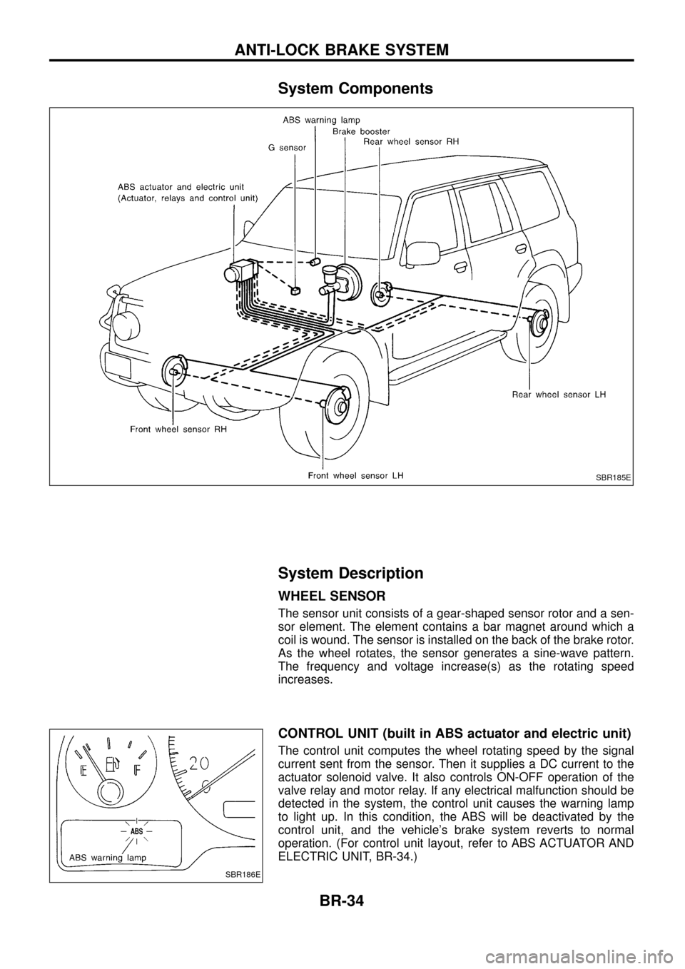
System Components
System Description
WHEEL SENSOR
The sensor unit consists of a gear-shaped sensor rotor and a sen-
sor element. The element contains a bar magnet around which a
coil is wound. The sensor is installed on the back of the brake rotor.
As the wheel rotates, the sensor generates a sine-wave pattern.
The frequency and voltage increase(s) as the rotating speed
increases.
CONTROL UNIT (built in ABS actuator and electric unit)
The control unit computes the wheel rotating speed by the signal
current sent from the sensor. Then it supplies a DC current to the
actuator solenoid valve. It also controls ON-OFF operation of the
valve relay and motor relay. If any electrical malfunction should be
detected in the system, the control unit causes the warning lamp
to light up. In this condition, the ABS will be deactivated by the
control unit, and the vehicle's brake system reverts to normal
operation. (For control unit layout, refer to ABS ACTUATOR AND
ELECTRIC UNIT, BR-34.)
SBR185E
SBR186E
ANTI-LOCK BRAKE SYSTEM
BR-34
Page 37 of 75
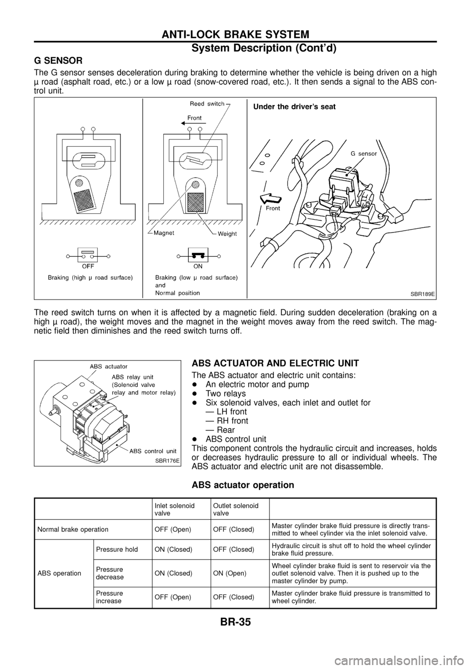
G SENSOR
The G sensor senses deceleration during braking to determine whether the vehicle is being driven on a high
road (asphalt road, etc.) or a low road (snow-covered road, etc.). It then sends a signal to the ABS con-
trol unit.
The reed switch turns on when it is affected by a magnetic ®eld. During sudden deceleration (braking on a
high road), the weight moves and the magnet in the weight moves away from the reed switch. The mag-
netic ®eld then diminishes and the reed switch turns off.
ABS ACTUATOR AND ELECTRIC UNIT
The ABS actuator and electric unit contains:
+An electric motor and pump
+ Two relays
+ Six solenoid valves, each inlet and outlet for
Ð LH front
Ð RH front
Ð Rear
+ ABS control unit
This component controls the hydraulic circuit and increases, holds
or decreases hydraulic pressure to all or individual wheels. The
ABS actuator and electric unit are not disassemble.
ABS actuator operation
Inlet solenoid
valve Outlet solenoid
valve
Normal brake operation OFF (Open) OFF (Closed) Master cylinder brake ¯uid pressure is directly trans-
mitted to wheel cylinder via the inlet solenoid valve.
ABS operation Pressure hold ON (Closed) OFF (Closed)
Hydraulic circuit is shut off to hold the wheel cylinder
brake ¯uid pressure.
Pressure
decrease ON (Closed) ON (Open) Wheel cylinder brake ¯uid is sent to reservoir via the
outlet solenoid valve. Then it is pushed up to the
master cylinder by pump.
Pressure
increase OFF (Open) OFF (Closed) Master cylinder brake ¯uid pressure is transmitted to
wheel cylinder.
SBR189E
SBR176E
ANTI-LOCK BRAKE SYSTEM
System Description (Cont'd)
BR-35
Page 38 of 75
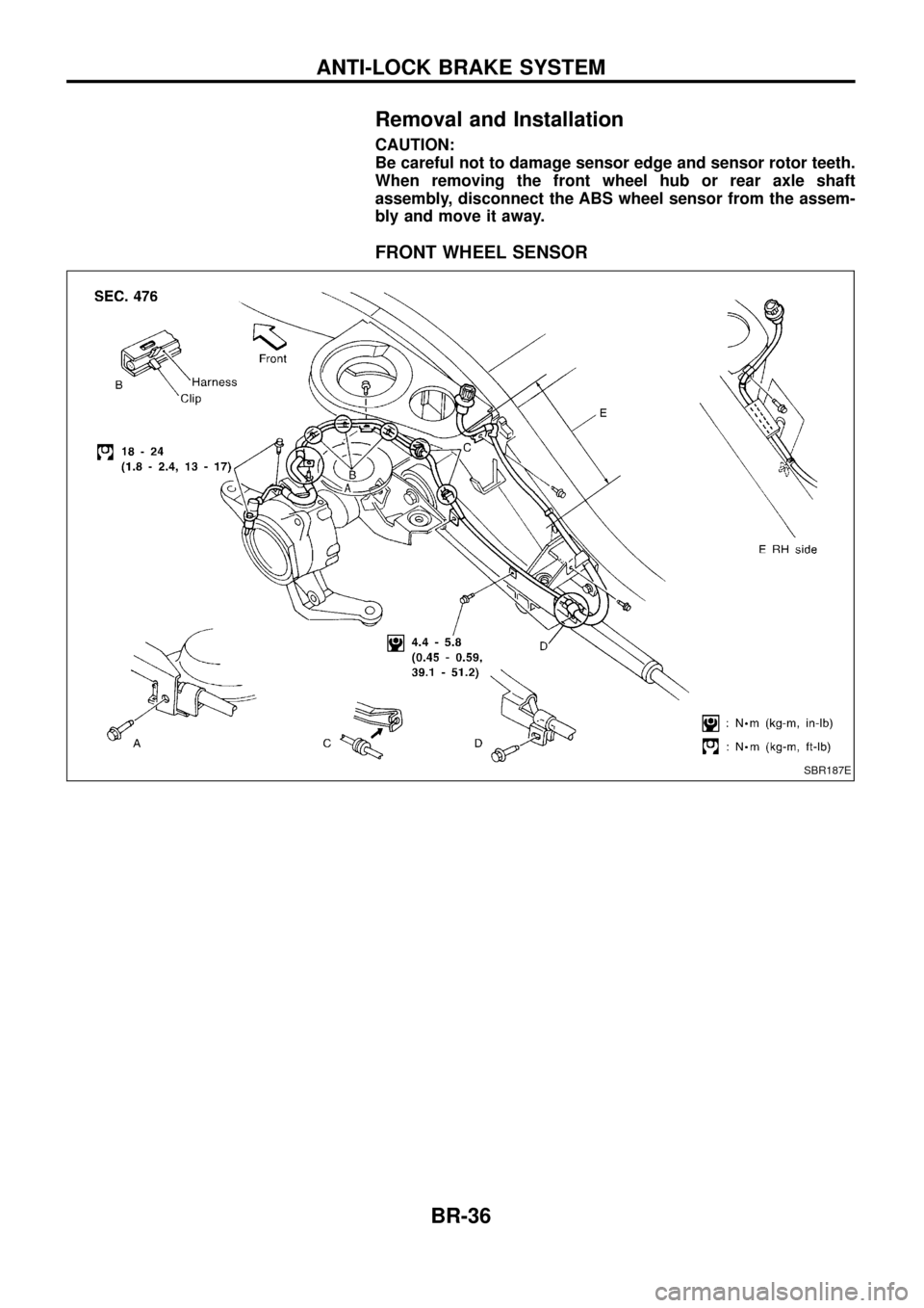
Removal and Installation
CAUTION:
Be careful not to damage sensor edge and sensor rotor teeth.
When removing the front wheel hub or rear axle shaft
assembly, disconnect the ABS wheel sensor from the assem-
bly and move it away.
FRONT WHEEL SENSOR
SBR187E
ANTI-LOCK BRAKE SYSTEM
BR-36
Page 39 of 75
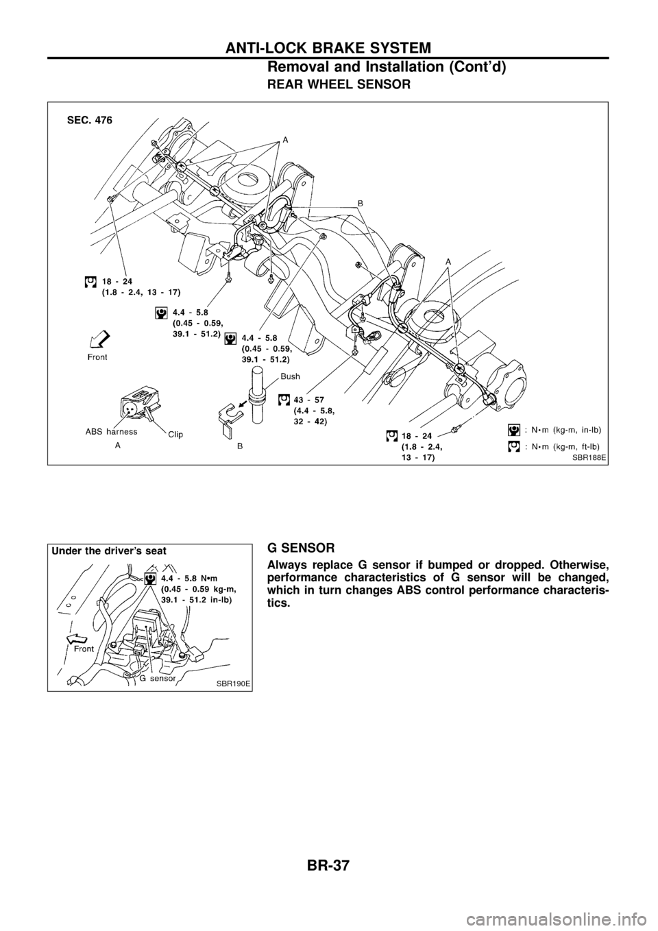
REAR WHEEL SENSOR
G SENSOR
Always replace G sensor if bumped or dropped. Otherwise,
performance characteristics of G sensor will be changed,
which in turn changes ABS control performance characteris-
tics.
SBR188E
SBR190E
ANTI-LOCK BRAKE SYSTEM
Removal and Installation (Cont'd)BR-37
Page 41 of 75
How to Perform Trouble Diagnoses for Quick
and Accurate Repair
INTRODUCTION
The ABS system has an electronic control unit to control major
functions. The control unit accepts input signals from sensors and
instantly drives the actuators. It is essential that both kinds of sig-
nals are proper and stable. It is also important to check for conven-
tional problems: such as air leaks in booster lines, lack of brake
¯uid, or other problems with the brake system.
It is much more difficult to diagnose a problem that occurs intermit-
tently rather than continuously. Most intermittent problems are
caused by poor electric connections or faulty wiring. In this case,
careful checking of suspicious circuits may help prevent the
replacement of good parts.
A visual check only may not ®nd the cause of the problems, so a
road test should be performed.
Before undertaking actual checks, take a few minutes to talk with
a customer who approaches with a ABS complaint. The customer
is a very good source of information on such problems; especially
intermittent ones. Through the talks with the customer, ®nd out what
symptoms are present and under what conditions they occur.
Start your diagnosis by looking for ``conventional'' problems ®rst.
This is one of the best ways to troubleshoot brake problems on an
ABS controlled vehicle.
SEF233G
SEF234G
TROUBLE DIAGNOSES
BR-39