1998 NISSAN PATROL service
[x] Cancel search: servicePage 1 of 75
BRAKE SYSTEM
SECTION
BR
CONTENTS
PRECAUTIONS AND PREPARATION ............................1
Supplemental Restraint System (SRS) ``AIR
BAG'' and ``SEAT BELT PRE-TENSIONER''...............1
Precautions for Brake System .....................................1
Commercial Service Tools ...........................................1
NOISE, VIBRATION AND HARSHNESS (NVH)
TROUBLESHOOTING .....................................................2
NVH Troubleshooting Chart.........................................2
CHECK AND ADJUSTMENT ..........................................3
Checking Brake Fluid Level.........................................3
Checking Brake Line ...................................................3
Changing Brake Fluid ..................................................3
Bleeding Brake System ...............................................4
BRAKE HYDRAULIC LINE/CONTROL VALVE ..............5
Brake Hydraulic Line ...................................................5
Load Sensing Valve .....................................................6
BRAKE PEDAL AND BRACKET ..................................10
Removal and Installation ...........................................10
Inspection...................................................................10
Adjustment .................................................................10
MASTER CYLINDER .....................................................12
Removal .....................................................................12
Disassembly...............................................................13
Inspection...................................................................13
Assembly ...................................................................13
Installation ..................................................................14
BRAKE BOOSTER ........................................................15
Brake Booster ............................................................15
VACUUM PIPING (LHD models) ..................................17
Vacuum Hose ............................................................17
VACUUM PIPING (RHD models) .................................18
Vacuum Hose ............................................................18
VACUUM PIPING ...........................................................19
VACUUM PUMP ............................................................20
Removal and Installation ...........................................20
FRONT DISC BRAKE ...................................................21
Pad Replacement ......................................................21
Removal .....................................................................23
Disassembly...............................................................23 Inspection Ð Caliper .................................................23
Inspection Ð Rotor ....................................................24
Assembly ...................................................................24
Installation ..................................................................24
REAR DISC BRAKE ......................................................25
Pad Replacement ......................................................25
Removal .....................................................................27
Disassembly...............................................................27
Inspection Ð Caliper .................................................27
Inspection Ð Rotor ....................................................28
Assembly ...................................................................28
Installation ..................................................................28
PARKING CENTER BRAKE CONTROL ......................29
Removal .....................................................................29
Inspection...................................................................29
Installation ..................................................................30
Adjustment .................................................................30
PARKING CENTER BRAKE .........................................31
Removal and Installation ...........................................31
Inspection Ð Drum ....................................................32
Inspection Ð Lining ...................................................32
ANTI-LOCK BRAKE SYSTEM ......................................33
Purpose......................................................................33
Operation ...................................................................33
ABS Hydraulic Circuit ................................................33
System Components .................................................34
System Description ....................................................34
Removal and Installation ...........................................36
TROUBLE DIAGNOSES ...............................................39
How to Perform Trouble Diagnoses for Quick
and Accurate Repair ..................................................39
Preliminary Check......................................................40
Component Parts and Harness Connector
Location .....................................................................41
Circuit Diagram for Quick Pinpoint Check.................42
Wiring Diagram Ð ABS Ð ........................................43
Self-diagnosis ............................................................47
CONSULT ..................................................................50
CONSULT Inspection Procedure...............................51
BR
Page 2 of 75
Ground Circuit Check ................................................56
TROUBLE DIAGNOSES FOR SELF-DIAGNOSTIC
ITEMS ........................................................................\
.....57
Diagnostic Procedure 1 (Wheel sensor or rotor) ......57
Diagnostic Procedure 2 (ABS actuator solenoid
valve and solenoid valve relay) .................................59
Diagnostic Procedure 3 (Motor relay or motor).........61
Diagnostic Procedure 4 (Low voltage) ......................63
Diagnostic Procedure 5 (G sensor) ...........................64
Diagnostic Procedure 6 (Control unit) .......................65
TROUBLE DIAGNOSES FOR SYMPTOMS .................66
Diagnostic Procedure 7 (ABS works frequently.) ......66
Diagnostic Procedure 8 (Unexpected pedal
action) ........................................................................\
67 Diagnostic Procedure 9 (Long stopping distance) ....67
Diagnostic Procedure 10 (ABS does not work.) .......68
Diagnostic Procedure 11 (Pedal vibration and
noise) ........................................................................\
.68
Diagnostic Procedure 12 (Warning lamp does
not come on when ignition switch is turned ON.) .....69
Diagnostic Procedure 13 (Warning lamp stays on
when ignition switch is turned ON.)...........................71
SERVICE DATA AND SPECIFICATIONS (SDS) ..........72
General Speci®cations ...............................................72
Inspection and Adjustment ........................................73
When you read wiring diagrams:
+ Read GI section, ``HOW TO READ WIRING DIAGRAMS''.
+ See EL section, ``POWER SUPPLY ROUTING'' for power distribution circuit.
When you perform trouble diagnoses, read GI section, ``HOW TO FOLLOW FLOW CHART
IN TROUBLE DIAGNOSES'' and ``HOW TO PERFORM EFFICIENT DIAGNOSIS FOR AN
ELECTRICAL INCIDENT''.
Page 3 of 75
Supplemental Restraint System (SRS) ``AIR
BAG'' and ``SEAT BELT PRE-TENSIONER''
The Supplemental Restraint System such as ``AIR BAG'' and ``SEAT BELT PRE-TENSIONER'' used along with
a seat belt, helps to reduce the risk or severity of injury to the driver and front passenger in a frontal collision.
The SRS system composition which is available to NISSAN MODEL Y61 is as follows (The composition var-
ies according to the destination.):
Driver air bag module (located in the center of the steering wheel), front passenger air bag module (located
on the instrument panel on passenger side), seat belt pre-tensioner, a diagnosis sensor unit, warning lamp,
wiring harness and spiral cable.
Information necessary to service the system safely is included in theRS sectionof this Service Manual.
WARNING:
+ To avoid rendering the SRS inoperative, which could increase the risk of personal injury or death
in the event of a collision which would result in air bag in¯ation, all maintenance must be performed
by an authorized NISSAN dealer.
+ Improper maintenance, including incorrect removal and installation of the SRS, can lead to per-
sonal injury caused by unintentional activation of the system. For removal of Spiral Cable and Air
Bag Module, see the RS section.
+ Do not use electrical test equipment on any circuit related to the SRS unless instructed to in this
Service Manual. Spiral Cable and wiring harnesses covered with yellow insulation either just before
the harness connectors or for the complete harness are related to the SRS.
Precautions for Brake System
+Use brake ¯uid ``DOT 3''.
+ Never reuse drained brake ¯uid.
+ Be careful not to splash brake ¯uid on painted areas; it
may cause paint damage. If brake ¯uid is splashed on
painted areas, wash it away with water immediately.
+ To clean master cylinder parts, disc brake caliper parts or
wheel cylinder parts, use clean brake ¯uid.
+ Never use mineral oils such as gasoline or kerosene. They
will ruin rubber parts of hydraulic system.
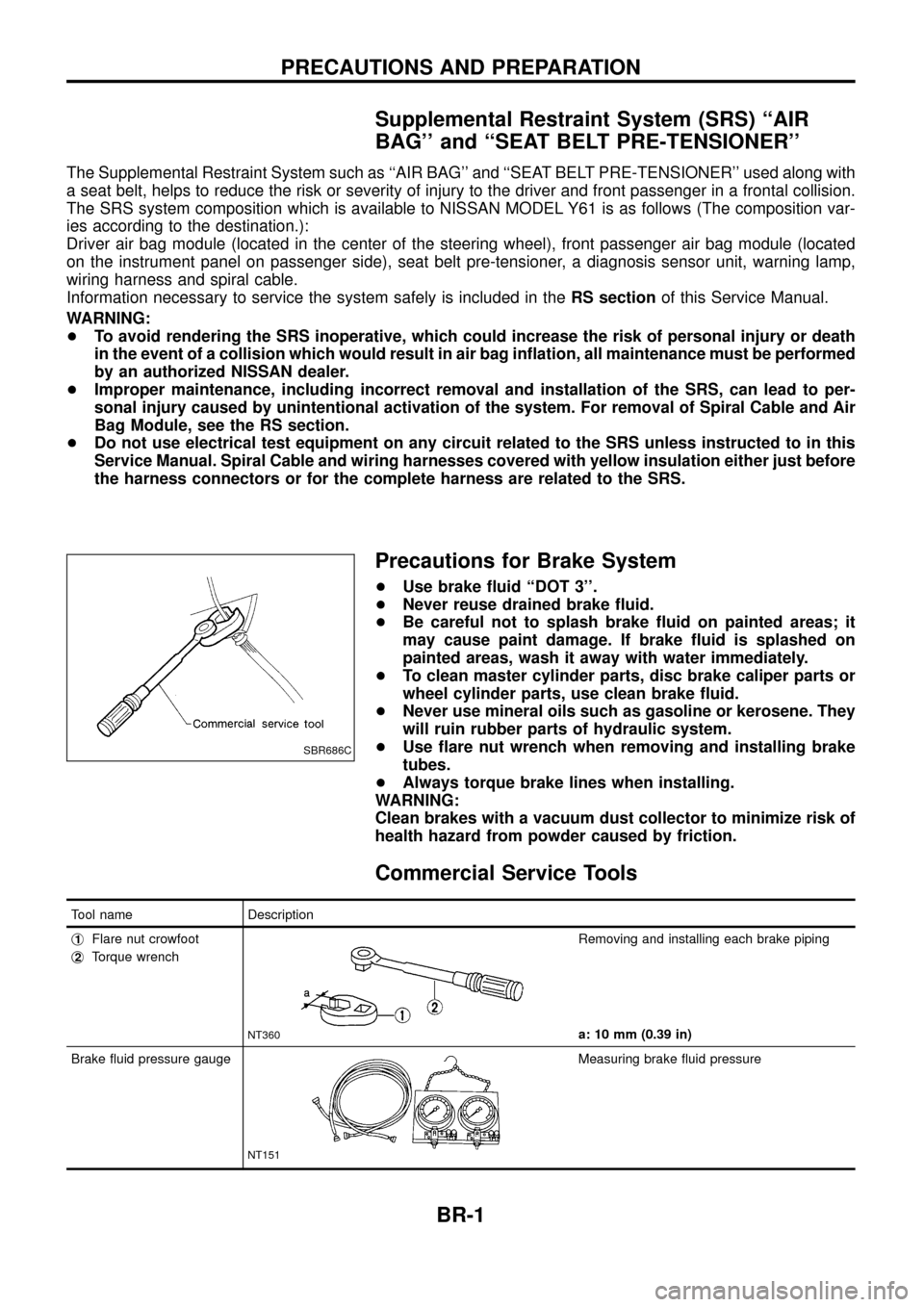
+ Use ¯are nut wrench when removing and installing brake
tubes.
+ Always torque brake lines when installing.
WARNING:
Clean brakes with a vacuum dust collector to minimize risk of
health hazard from powder caused by friction.
Commercial Service Tools
Tool name Description
j
1Flare nut crowfoot
j
2Torque wrench
NT360
Removing and installing each brake piping
a: 10 mm (0.39 in)
Brake ¯uid pressure gauge
NT151
Measuring brake ¯uid pressure
SBR686C
PRECAUTIONS AND PREPARATION
BR-1
Page 17 of 75
Brake Booster
ON-VEHICLE SERVICE
Operating check
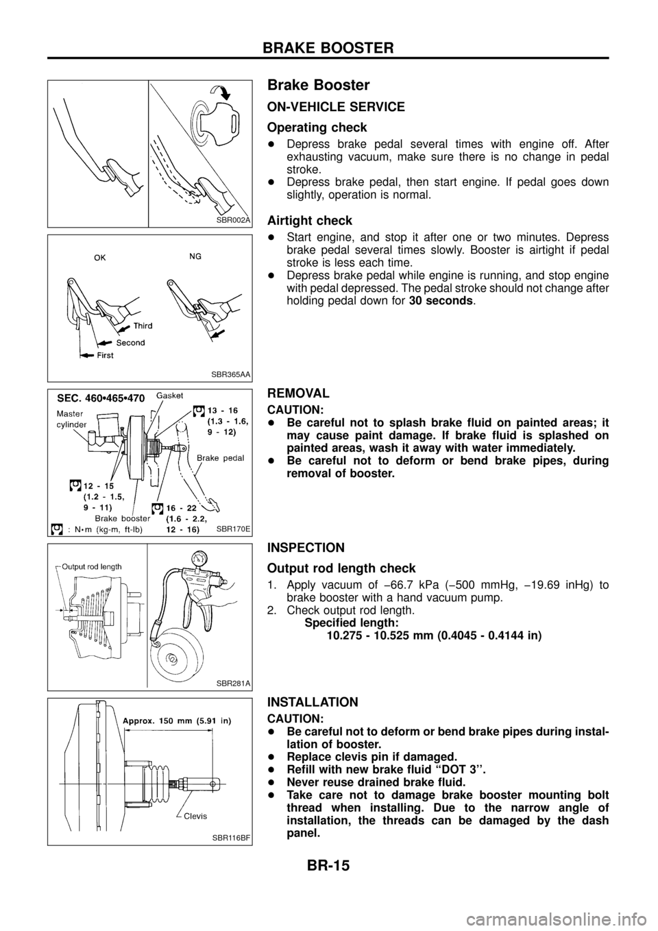
+Depress brake pedal several times with engine off. After
exhausting vacuum, make sure there is no change in pedal
stroke.
+ Depress brake pedal, then start engine. If pedal goes down
slightly, operation is normal.
Airtight check
+Start engine, and stop it after one or two minutes. Depress
brake pedal several times slowly. Booster is airtight if pedal
stroke is less each time.
+ Depress brake pedal while engine is running, and stop engine
with pedal depressed. The pedal stroke should not change after
holding pedal down for 30 seconds.
REMOVAL
CAUTION:
+Be careful not to splash brake ¯uid on painted areas; it
may cause paint damage. If brake ¯uid is splashed on
painted areas, wash it away with water immediately.
+ Be careful not to deform or bend brake pipes, during
removal of booster.
INSPECTION
Output rod length check
1. Apply vacuum of þ66.7 kPa (þ500 mmHg, þ19.69 inHg) to
brake booster with a hand vacuum pump.
2. Check output rod length. Speci®ed length:10.275 - 10.525 mm (0.4045 - 0.4144 in)
INSTALLATION
CAUTION:
+Be careful not to deform or bend brake pipes during instal-
lation of booster.
+ Replace clevis pin if damaged.
+ Re®ll with new brake ¯uid ``DOT 3''.
+ Never reuse drained brake ¯uid.
+ Take care not to damage brake booster mounting bolt
thread when installing. Due to the narrow angle of
installation, the threads can be damaged by the dash
panel.
SBR002A
SBR365AA
SBR170E
SBR281A
SBR116BF
BRAKE BOOSTER
BR-15
Page 26 of 75
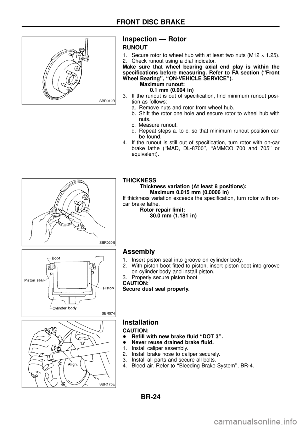
Inspection Ð Rotor
RUNOUT
1. Secure rotor to wheel hub with at least two nuts (M12 ý 1.25).
2. Check runout using a dial indicator.
Make sure that wheel bearing axial end play is within the
speci®cations before measuring. Refer to FA section (``Front
Wheel Bearing'', ``ON-VEHICLE SERVICE'').Maximum runout:0.1 mm (0.004 in)
3. If the runout is out of speci®cation, ®nd minimum runout posi- tion as follows:
a. Remove nuts and rotor from wheel hub.
b. Shift the rotor one hole and secure rotor to wheel hub withnuts.
c. Measure runout.
d. Repeat steps a. to c. so that minimum runout position can be found.
4. If the runout is still out of speci®cation, turn rotor with on-car brake lathe (``MAD, DL-8700'', ``AMMCO 700 and 705'' or
equivalent).
THICKNESS
Thickness variation (At least 8 positions): Maximum 0.015 mm (0.0006 in)
If thickness variation exceeds the speci®cation, turn rotor with on-
car brake lathe. Rotor repair limit:30.0 mm (1.181 in)
Assembly
1. Insert piston seal into groove on cylinder body.
2. With piston boot ®tted to piston, insert piston boot into grooveon cylinder body and install piston.
3. Properly secure piston boot
CAUTION:
Secure dust seal properly.
Installation
CAUTION:
+ Re®ll with new brake ¯uid ``DOT 3''.
+ Never reuse drained brake ¯uid.
1. Install caliper assembly.
2. Install brake hose to caliper securely.
3. Install all parts and secure all bolts.
4. Bleed air. Refer to ``Bleeding Brake System'', BR-4.
SBR019B
SBR020B
SBR574
SBR175E
FRONT DISC BRAKE
BR-24
Page 68 of 75
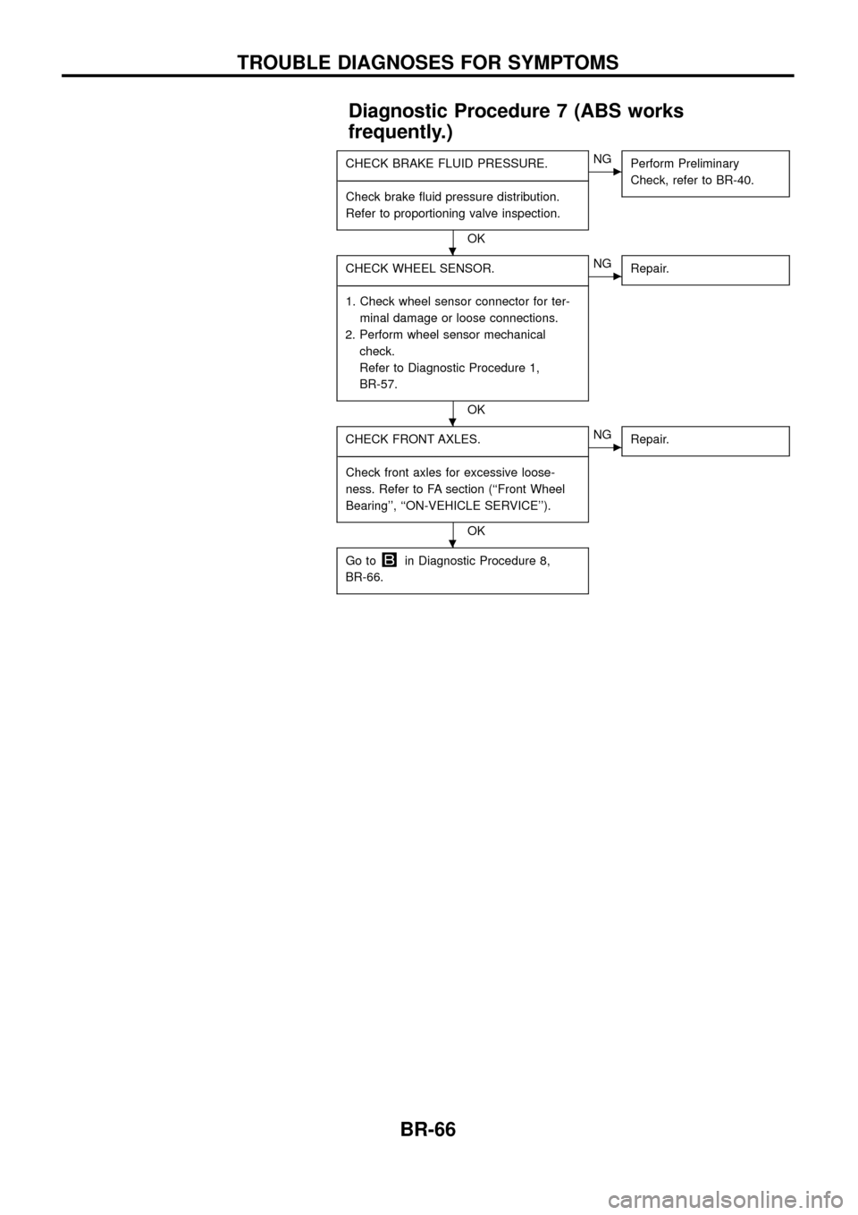
Diagnostic Procedure 7 (ABS works
frequently.)
CHECK BRAKE FLUID PRESSURE.
- ---------------------------------------------------------------------------------------------------------------------------------------------------------------------------------------------------------------------------------------------------------------------------------------------------------------
Check brake ¯uid pressure distribution.
Refer to proportioning valve inspection.
OK
cNG Perform Preliminary
Check, refer to BR-40.
CHECK WHEEL SENSOR.
- ---------------------------------------------------------------------------------------------------------------------------------------------------------------------------------------------------------------------------------------------------------------------------------------------------------------
1. Check wheel sensor connector for ter- minal damage or loose connections.
2. Perform wheel sensor mechanical check.
Refer to Diagnostic Procedure 1,
BR-57.
OK
cNG Repair.
CHECK FRONT AXLES.
- ---------------------------------------------------------------------------------------------------------------------------------------------------------------------------------------------------------------------------------------------------------------------------------------------------------------
Check front axles for excessive loose-
ness. Refer to FA section (``Front Wheel
Bearing'', ``ON-VEHICLE SERVICE'').
OK
cNG Repair.
Go toin Diagnostic Procedure 8,
BR-66.
.
.
.
TROUBLE DIAGNOSES FOR SYMPTOMS
BR-66
Page 74 of 75
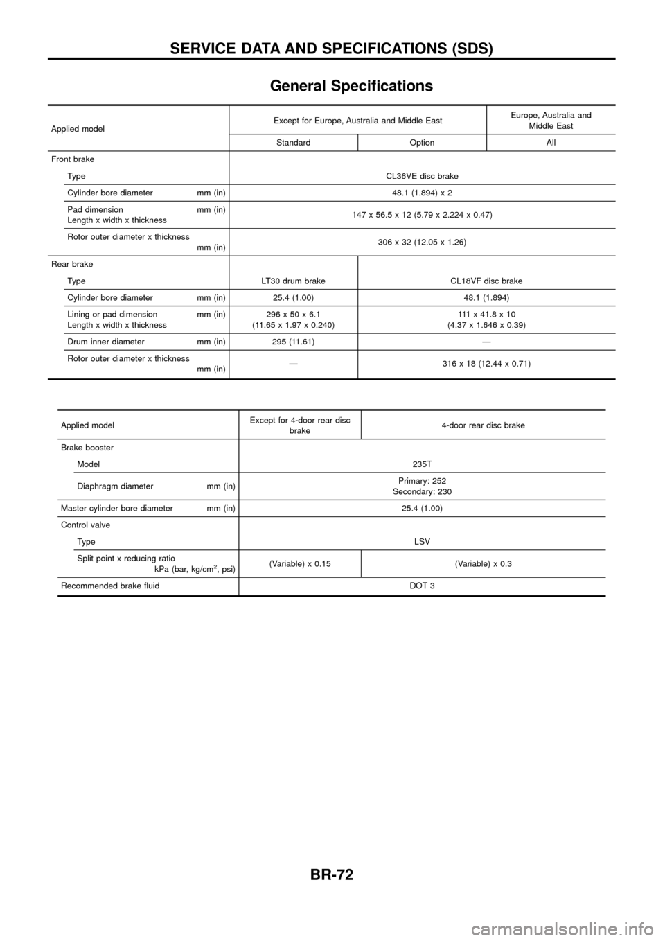
General Speci®cations
Applied modelExcept for Europe, Australia and Middle East
Europe, Australia and
Middle East
Standard Option All
Front brake Type CL36VE disc brake
Cylinder bore diameter mm (in) 48.1 (1.894) x 2
Pad dimension mm (in)
Length x width x thickness 147 x 56.5 x 12 (5.79 x 2.224 x 0.47)
Rotor outer diameter x thickness mm (in) 306 x 32 (12.05 x 1.26)
Rear brake Type LT30 drum brake CL18VF disc brake
Cylinder bore diameter mm (in) 25.4 (1.00) 48.1 (1.894)
Lining or pad dimension mm (in)
Length x width x thickness 296x50x6.1
(11.65 x 1.97 x 0.240) 111x41.8x10
(4.37 x 1.646 x 0.39)
Drum inner diameter mm (in) 295 (11.61) Ð
Rotor outer diameter x thickness mm (in)Ð 316 x 18 (12.44 x 0.71)
Applied model Except for 4-door rear disc
brake 4-door rear disc brake
Brake booster Model 235T
Diaphragm diameter mm (in) Primary: 252
Secondary: 230
Master cylinder bore diameter mm (in) 25.4 (1.00)
Control valve Type LSV
Split point x reducing ratio kPa (bar, kg/cm
2, psi)(Variable) x 0.15 (Variable) x 0.3
Recommended brake ¯uid DOT 3
SERVICE DATA AND SPECIFICATIONS (SDS)
BR-72
Page 75 of 75
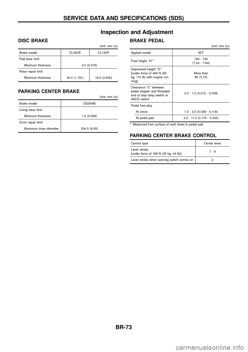
Inspection and Adjustment
DISC BRAKE
Unit: mm (in)
Brake model CL36VE CL18VF
Pad wear limit
Minimum thickness 2.0 (0.079)
Rotor repair limit
Minimum thickness 30.0 (1.181) 16.0 (0.630)
PARKING CENTER BRAKE
Unit: mm (in)
Brake model DS20HB
Lining wear limit
Minimum thickness 1.5 (0.059)
Drum repair limit
Maximum inner diameter 204.5 (8.05)
BRAKE PEDAL
Unit: mm (in)
Applied model M/T
Free height ``H''*184 - 194
(7.24 - 7.64)
Depressed height ``D''
[under force of 490 N (50
kg, 110 lb) with engine run-
ning]More than
80 (3.15)
Clearance ``C'' between
pedal stopper and threaded
end of stop lamp switch or
ASCD switch0.3 - 1.0 (0.012 - 0.039)
Pedal free play
At clevis 1.0 - 3.0 (0.039 - 0.118)
At pedal pad 3.0 - 11.0 (0.118 - 0.433)
*: Measured from surface of melt sheet to pedal pad.
PARKING CENTER BRAKE CONTROL
Control type Center lever
Lever stroke
[under force of 196 N (20 kg, 44 lb)]7-9
Lever stroke when warning switch comes on 2
SERVICE DATA AND SPECIFICATIONS (SDS)
BR-73