1998 NISSAN PATROL PARKING
[x] Cancel search: PARKINGPage 1 of 75
BRAKE SYSTEM
SECTION
BR
CONTENTS
PRECAUTIONS AND PREPARATION ............................1
Supplemental Restraint System (SRS) ``AIR
BAG'' and ``SEAT BELT PRE-TENSIONER''...............1
Precautions for Brake System .....................................1
Commercial Service Tools ...........................................1
NOISE, VIBRATION AND HARSHNESS (NVH)
TROUBLESHOOTING .....................................................2
NVH Troubleshooting Chart.........................................2
CHECK AND ADJUSTMENT ..........................................3
Checking Brake Fluid Level.........................................3
Checking Brake Line ...................................................3
Changing Brake Fluid ..................................................3
Bleeding Brake System ...............................................4
BRAKE HYDRAULIC LINE/CONTROL VALVE ..............5
Brake Hydraulic Line ...................................................5
Load Sensing Valve .....................................................6
BRAKE PEDAL AND BRACKET ..................................10
Removal and Installation ...........................................10
Inspection...................................................................10
Adjustment .................................................................10
MASTER CYLINDER .....................................................12
Removal .....................................................................12
Disassembly...............................................................13
Inspection...................................................................13
Assembly ...................................................................13
Installation ..................................................................14
BRAKE BOOSTER ........................................................15
Brake Booster ............................................................15
VACUUM PIPING (LHD models) ..................................17
Vacuum Hose ............................................................17
VACUUM PIPING (RHD models) .................................18
Vacuum Hose ............................................................18
VACUUM PIPING ...........................................................19
VACUUM PUMP ............................................................20
Removal and Installation ...........................................20
FRONT DISC BRAKE ...................................................21
Pad Replacement ......................................................21
Removal .....................................................................23
Disassembly...............................................................23 Inspection Ð Caliper .................................................23
Inspection Ð Rotor ....................................................24
Assembly ...................................................................24
Installation ..................................................................24
REAR DISC BRAKE ......................................................25
Pad Replacement ......................................................25
Removal .....................................................................27
Disassembly...............................................................27
Inspection Ð Caliper .................................................27
Inspection Ð Rotor ....................................................28
Assembly ...................................................................28
Installation ..................................................................28
PARKING CENTER BRAKE CONTROL ......................29
Removal .....................................................................29
Inspection...................................................................29
Installation ..................................................................30
Adjustment .................................................................30
PARKING CENTER BRAKE .........................................31
Removal and Installation ...........................................31
Inspection Ð Drum ....................................................32
Inspection Ð Lining ...................................................32
ANTI-LOCK BRAKE SYSTEM ......................................33
Purpose......................................................................33
Operation ...................................................................33
ABS Hydraulic Circuit ................................................33
System Components .................................................34
System Description ....................................................34
Removal and Installation ...........................................36
TROUBLE DIAGNOSES ...............................................39
How to Perform Trouble Diagnoses for Quick
and Accurate Repair ..................................................39
Preliminary Check......................................................40
Component Parts and Harness Connector
Location .....................................................................41
Circuit Diagram for Quick Pinpoint Check.................42
Wiring Diagram Ð ABS Ð ........................................43
Self-diagnosis ............................................................47
CONSULT ..................................................................50
CONSULT Inspection Procedure...............................51
BR
Page 5 of 75
Checking Brake Fluid Level
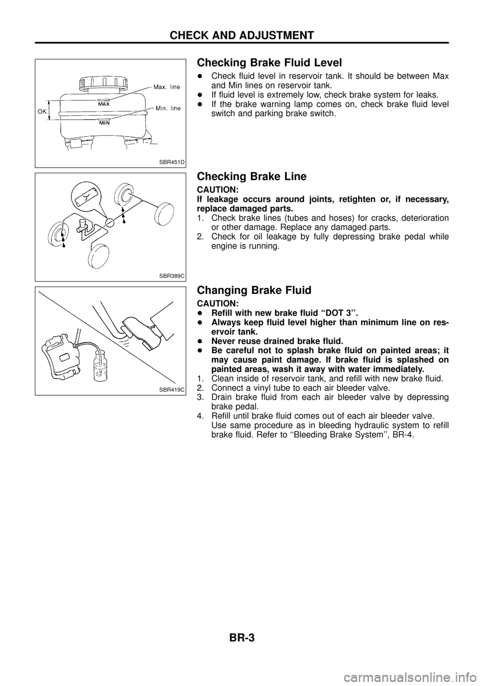
+Check ¯uid level in reservoir tank. It should be between Max
and Min lines on reservoir tank.
+ If ¯uid level is extremely low, check brake system for leaks.
+ If the brake warning lamp comes on, check brake ¯uid level
switch and parking brake switch.
Checking Brake Line
CAUTION:
If leakage occurs around joints, retighten or, if necessary,
replace damaged parts.
1. Check brake lines (tubes and hoses) for cracks, deterioration
or other damage. Replace any damaged parts.
2. Check for oil leakage by fully depressing brake pedal while engine is running.
Changing Brake Fluid
CAUTION:
+Re®ll with new brake ¯uid ``DOT 3''.
+ Always keep ¯uid level higher than minimum line on res-
ervoir tank.
+ Never reuse drained brake ¯uid.
+ Be careful not to splash brake ¯uid on painted areas; it
may cause paint damage. If brake ¯uid is splashed on
painted areas, wash it away with water immediately.
1. Clean inside of reservoir tank, and re®ll with new brake ¯uid.
2. Connect a vinyl tube to each air bleeder valve.
3. Drain brake ¯uid from each air bleeder valve by depressing brake pedal.
4. Re®ll until brake ¯uid comes out of each air bleeder valve. Use same procedure as in bleeding hydraulic system to re®ll
brake ¯uid. Refer to ``Bleeding Brake System'', BR-4.
SBR451D
SBR389C
SBR419C
CHECK AND ADJUSTMENT
BR-3
Page 31 of 75
Removal
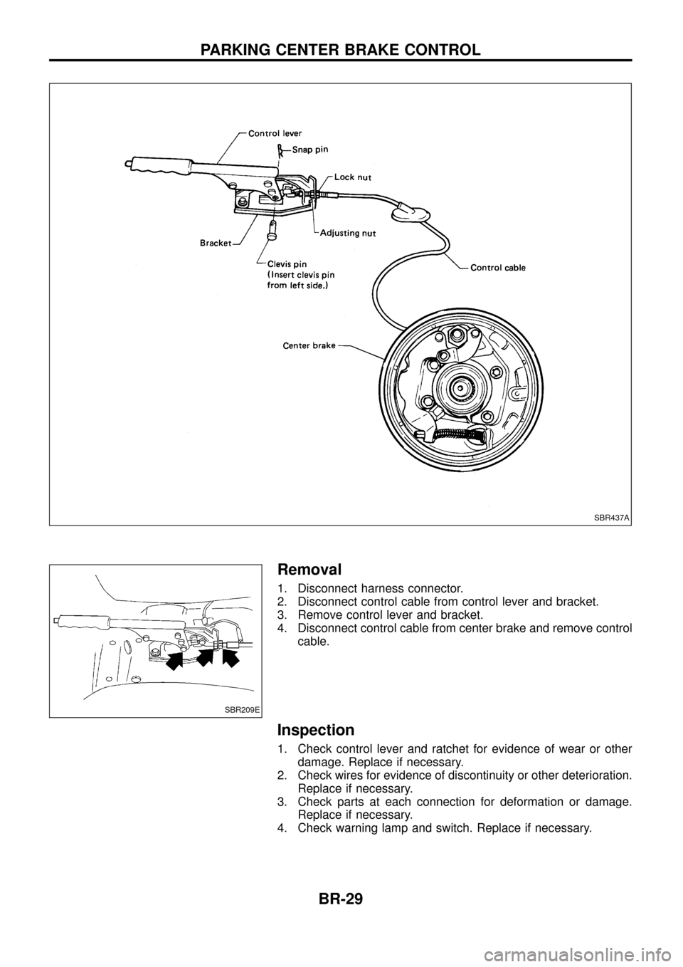
1. Disconnect harness connector.
2. Disconnect control cable from control lever and bracket.
3. Remove control lever and bracket.
4. Disconnect control cable from center brake and remove controlcable.
Inspection
1. Check control lever and ratchet for evidence of wear or otherdamage. Replace if necessary.
2. Check wires for evidence of discontinuity or other deterioration. Replace if necessary.
3. Check parts at each connection for deformation or damage. Replace if necessary.
4. Check warning lamp and switch. Replace if necessary.
SBR437A
SBR209E
PARKING CENTER BRAKE CONTROL
BR-29
Page 32 of 75
Installation
1. Apply a coating of grease to sliding contact surfaces.
2. Insert clevis pin from left side.
3. After installation is completed, adjust entire system.
Adjustment
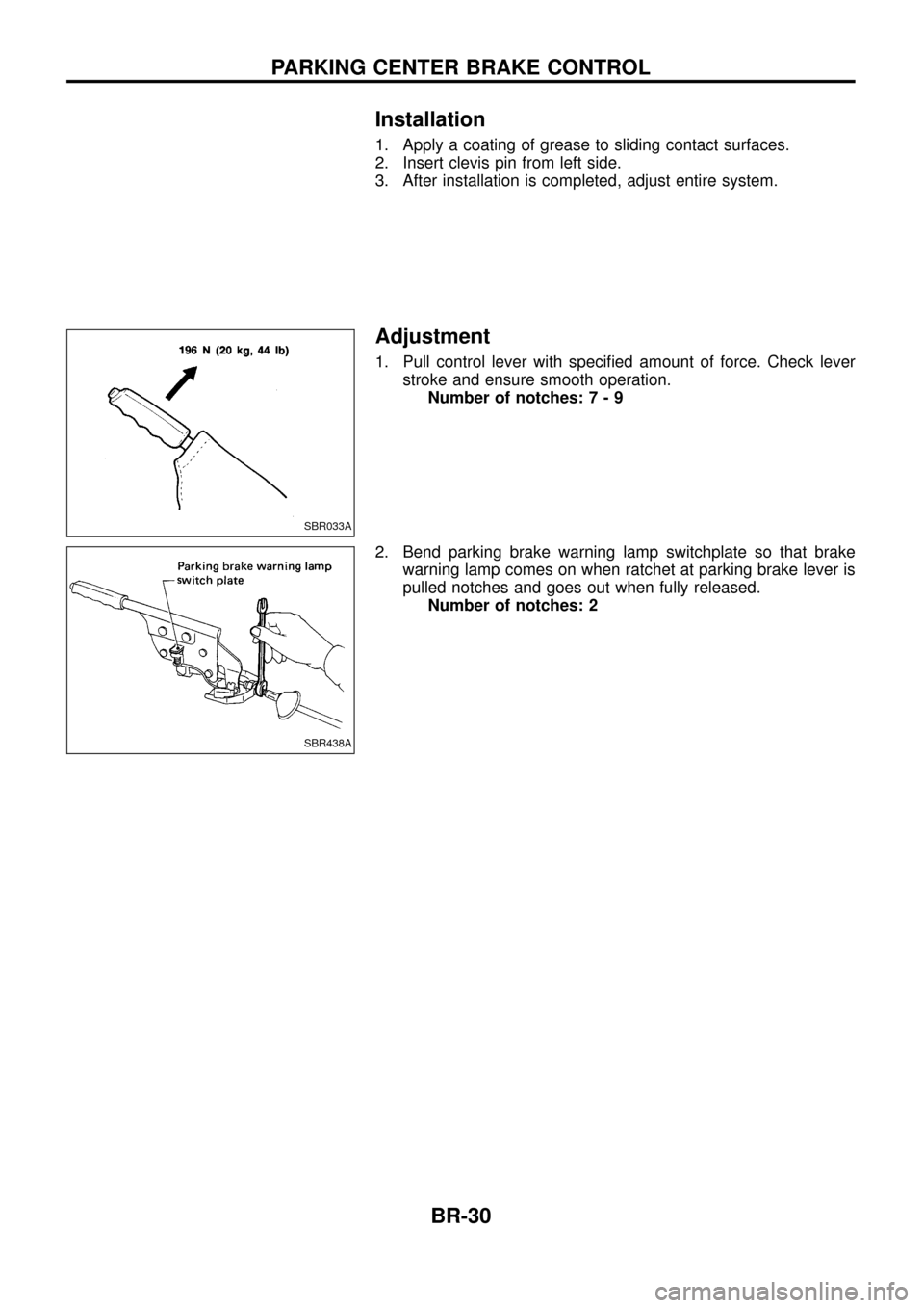
1. Pull control lever with speci®ed amount of force. Check leverstroke and ensure smooth operation.Number of notches :7-9
2. Bend parking brake warning lamp switchplate so that brake warning lamp comes on when ratchet at parking brake lever is
pulled notches and goes out when fully released.Number of notches: 2
SBR033A
SBR438A
PARKING CENTER BRAKE CONTROL
BR-30
Page 33 of 75
Removal and Installation
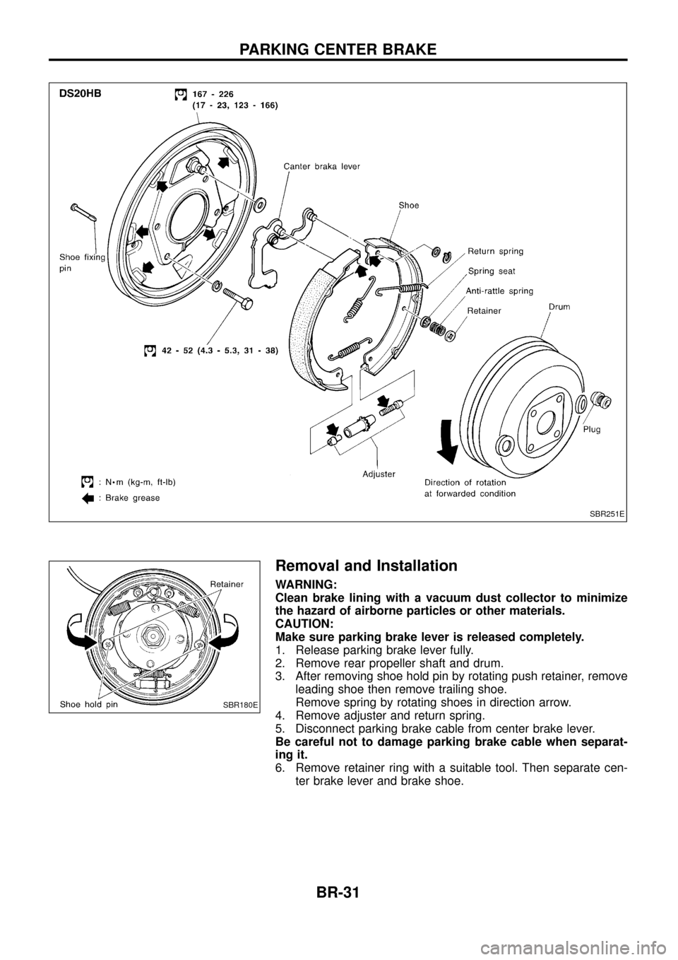
WARNING:
Clean brake lining with a vacuum dust collector to minimize
the hazard of airborne particles or other materials.
CAUTION:
Make sure parking brake lever is released completely.
1. Release parking brake lever fully.
2. Remove rear propeller shaft and drum.
3. After removing shoe hold pin by rotating push retainer, removeleading shoe then remove trailing shoe.
Remove spring by rotating shoes in direction arrow.
4. Remove adjuster and return spring.
5. Disconnect parking brake cable from center brake lever.
Be careful not to damage parking brake cable when separat-
ing it.
6. Remove retainer ring with a suitable tool. Then separate cen- ter brake lever and brake shoe.
SBR251E
SBR180E
PARKING CENTER BRAKE
BR-31
Page 34 of 75
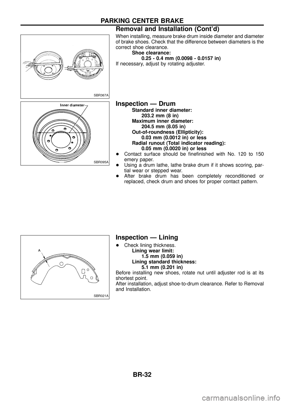
When installing, measure brake drum inside diameter and diameter
of brake shoes. Check that the difference between diameters is the
correct shoe clearance.Shoe clearance:0.25 - 0.4 mm (0.0098 - 0.0157 in)
If necessary, adjust by rotating adjuster.
Inspection Ð Drum
Standard inner diameter: 203.2 mm (8 in)
Maximum inner diameter: 204.5 mm (8.05 in)
Out-of-roundness (Ellipticity): 0.03 mm (0.0012 in) or less
Radial runout (Total indicator reading): 0.05 mm (0.0020 in) or less
+ Contact surface should be ®ne®nished with No. 120 to 150
emery paper.
+ Using a drum lathe, lathe brake drum if it shows scoring, par-
tial wear or stepped wear.
+ After brake drum has been completely reconditioned or
replaced, check drum and shoes for proper contact pattern.
Inspection Ð Lining
+Check lining thickness.
Lining wear limit: 1.5 mm (0.059 in)
Lining standard thickness: 5.1 mm (0.201 in)
Before installing new shoes, rotate nut until adjuster rod is at its
shortest point.
After installation, adjust shoe-to-drum clearance. Refer to Removal
and Installation.
SBR367A
SBR095A
SBR021A
PARKING CENTER BRAKE
Removal and Installation (Cont'd)
BR-32
Page 75 of 75
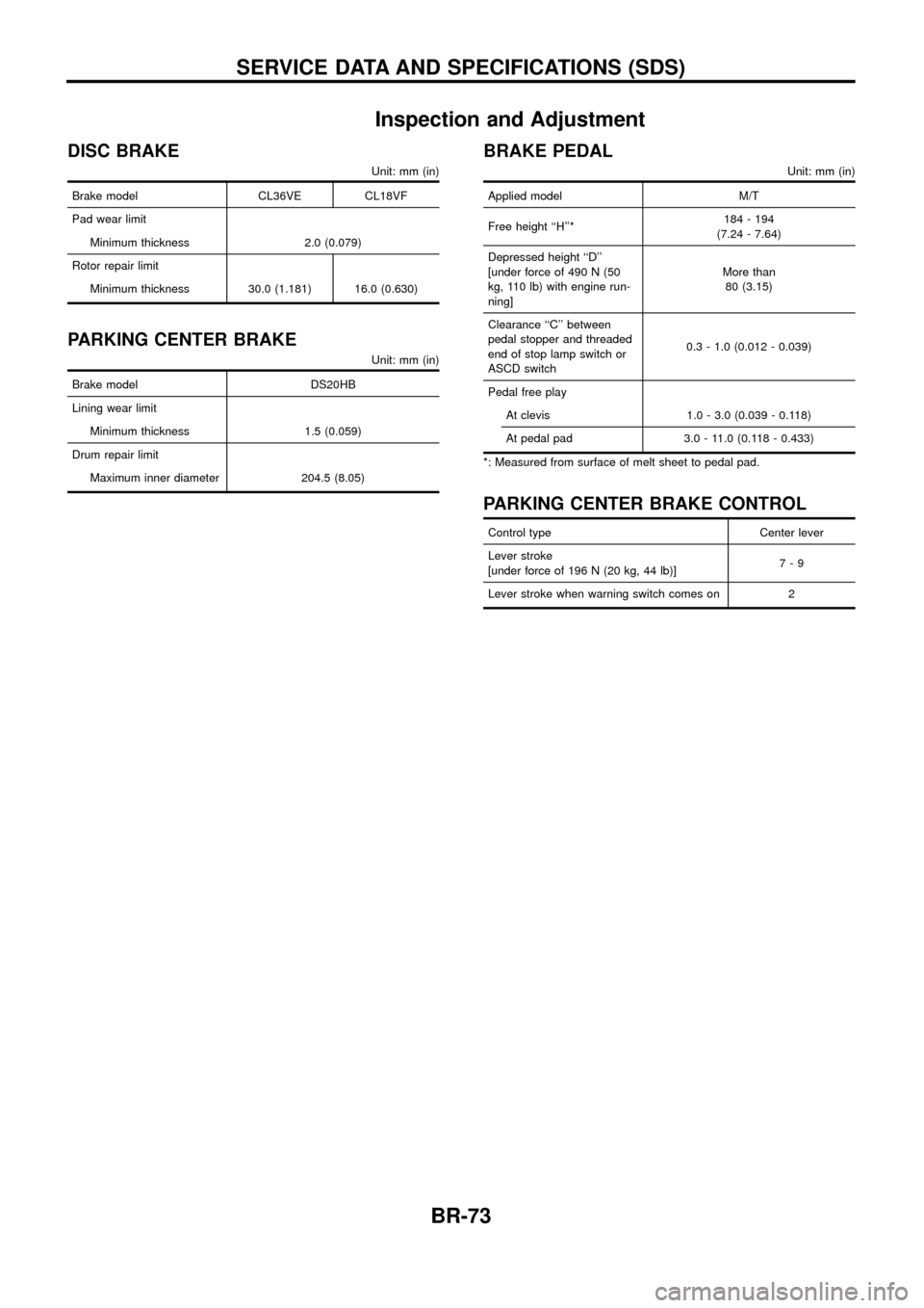
Inspection and Adjustment
DISC BRAKE
Unit: mm (in)
Brake model CL36VE CL18VF
Pad wear limit
Minimum thickness 2.0 (0.079)
Rotor repair limit
Minimum thickness 30.0 (1.181) 16.0 (0.630)
PARKING CENTER BRAKE
Unit: mm (in)
Brake model DS20HB
Lining wear limit
Minimum thickness 1.5 (0.059)
Drum repair limit
Maximum inner diameter 204.5 (8.05)
BRAKE PEDAL
Unit: mm (in)
Applied model M/T
Free height ``H''*184 - 194
(7.24 - 7.64)
Depressed height ``D''
[under force of 490 N (50
kg, 110 lb) with engine run-
ning]More than
80 (3.15)
Clearance ``C'' between
pedal stopper and threaded
end of stop lamp switch or
ASCD switch0.3 - 1.0 (0.012 - 0.039)
Pedal free play
At clevis 1.0 - 3.0 (0.039 - 0.118)
At pedal pad 3.0 - 11.0 (0.118 - 0.433)
*: Measured from surface of melt sheet to pedal pad.
PARKING CENTER BRAKE CONTROL
Control type Center lever
Lever stroke
[under force of 196 N (20 kg, 44 lb)]7-9
Lever stroke when warning switch comes on 2
SERVICE DATA AND SPECIFICATIONS (SDS)
BR-73