Page 32 of 75
Installation
1. Apply a coating of grease to sliding contact surfaces.
2. Insert clevis pin from left side.
3. After installation is completed, adjust entire system.
Adjustment
1. Pull control lever with speci®ed amount of force. Check leverstroke and ensure smooth operation.Number of notches :7-9
2. Bend parking brake warning lamp switchplate so that brake warning lamp comes on when ratchet at parking brake lever is
pulled notches and goes out when fully released.Number of notches: 2
SBR033A
SBR438A
PARKING CENTER BRAKE CONTROL
BR-30
Page 50 of 75

jA
Check warning lamp for deactivation after
driving vehicle over 30 km/h (19 MPH)
for at least one minute.
After making certain that warning lamp
does not come on, test the ABS in a safe
area to verify that it functions properly.
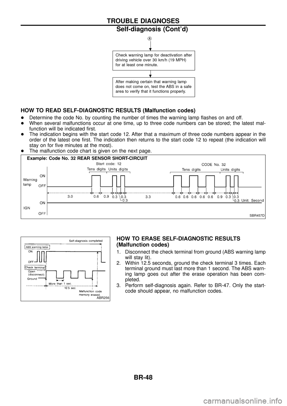
HOW TO READ SELF-DIAGNOSTIC RESULTS (Malfunction codes)
+Determine the code No. by counting the number of times the warning lamp ¯ashes on and off.
+ When several malfunctions occur at one time, up to three code numbers can be stored; the latest mal-
function will be indicated ®rst.
+ The indication begins with the start code 12. After that a maximum of three code numbers appear in the
order of the latest one ®rst. The indication then returns to the start code 12 to repeat (the indication will
stay on for ®ve minutes at the most).
+ The malfunction code chart is given on the next page.
HOW TO ERASE SELF-DIAGNOSTIC RESULTS
(Malfunction codes)
1. Disconnect the check terminal from ground (ABS warning lamp
will stay lit).
2. Within 12.5 seconds, ground the check terminal 3 times. Each terminal ground must last more than 1 second. The ABS warn-
ing lamp goes out after the erase operation has been com-
pleted.
3. Perform self-diagnosis again. Refer to BR-47. Only the start- code should appear, no malfunction codes.
SBR457D
ABR256
.
.
TROUBLE DIAGNOSES
Self-diagnosis (Cont'd)
BR-48
Page 52 of 75

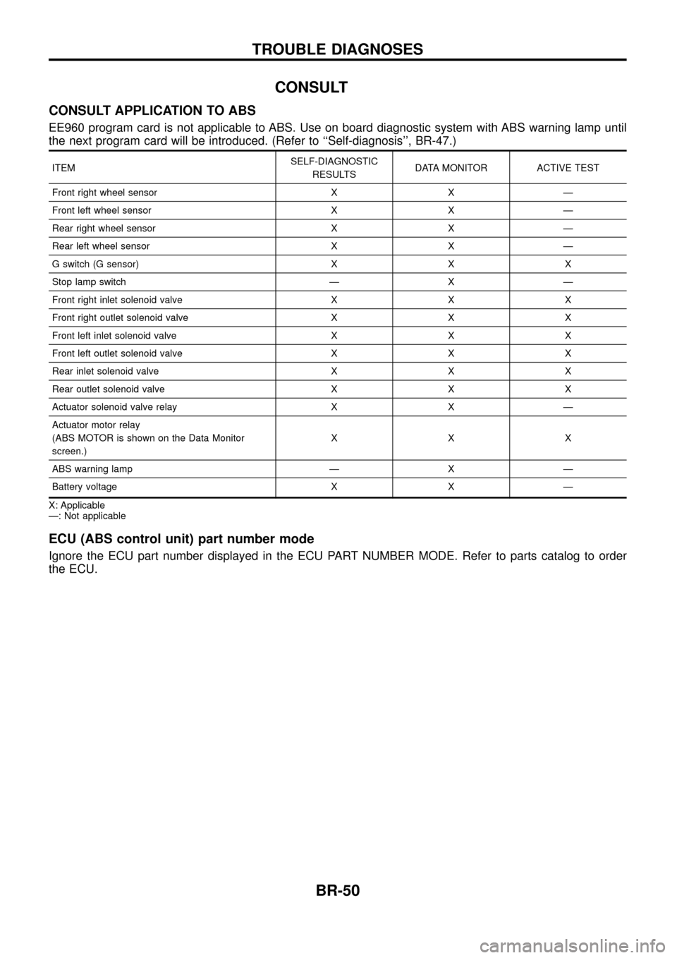
CONSULT
CONSULT APPLICATION TO ABS
EE960 program card is not applicable to ABS. Use on board diagnostic system with ABS warning lamp until
the next program card will be introduced. (Refer to ``Self-diagnosis'', BR-47.)
ITEMSELF-DIAGNOSTIC
RESULTS DATA MONITOR ACTIVE TEST
Front right wheel sensor X X Ð
Front left wheel sensor X X Ð
Rear right wheel sensor X X Ð
Rear left wheel sensor X X Ð
G switch (G sensor) X X X
Stop lamp switch Ð X Ð
Front right inlet solenoid valve X X X
Front right outlet solenoid valve X X X
Front left inlet solenoid valve X X X
Front left outlet solenoid valve X X X
Rear inlet solenoid valve X X X
Rear outlet solenoid valve X X X
Actuator solenoid valve relay X X Ð
Actuator motor relay
(ABS MOTOR is shown on the Data Monitor
screen.) XXX
ABS warning lamp Ð X Ð
Battery voltage X X Ð
X: Applicable
Ð: Not applicable
ECU (ABS control unit) part number mode
Ignore the ECU part number displayed in the ECU PART NUMBER MODE. Refer to parts catalog to order
the ECU.
TROUBLE DIAGNOSES
BR-50