Page 3 of 75

Supplemental Restraint System (SRS) ``AIR
BAG'' and ``SEAT BELT PRE-TENSIONER''
The Supplemental Restraint System such as ``AIR BAG'' and ``SEAT BELT PRE-TENSIONER'' used along with
a seat belt, helps to reduce the risk or severity of injury to the driver and front passenger in a frontal collision.
The SRS system composition which is available to NISSAN MODEL Y61 is as follows (The composition var-
ies according to the destination.):
Driver air bag module (located in the center of the steering wheel), front passenger air bag module (located
on the instrument panel on passenger side), seat belt pre-tensioner, a diagnosis sensor unit, warning lamp,
wiring harness and spiral cable.
Information necessary to service the system safely is included in theRS sectionof this Service Manual.
WARNING:
+ To avoid rendering the SRS inoperative, which could increase the risk of personal injury or death
in the event of a collision which would result in air bag in¯ation, all maintenance must be performed
by an authorized NISSAN dealer.
+ Improper maintenance, including incorrect removal and installation of the SRS, can lead to per-
sonal injury caused by unintentional activation of the system. For removal of Spiral Cable and Air
Bag Module, see the RS section.
+ Do not use electrical test equipment on any circuit related to the SRS unless instructed to in this
Service Manual. Spiral Cable and wiring harnesses covered with yellow insulation either just before
the harness connectors or for the complete harness are related to the SRS.
Precautions for Brake System
+Use brake ¯uid ``DOT 3''.
+ Never reuse drained brake ¯uid.
+ Be careful not to splash brake ¯uid on painted areas; it
may cause paint damage. If brake ¯uid is splashed on
painted areas, wash it away with water immediately.
+ To clean master cylinder parts, disc brake caliper parts or
wheel cylinder parts, use clean brake ¯uid.
+ Never use mineral oils such as gasoline or kerosene. They
will ruin rubber parts of hydraulic system.
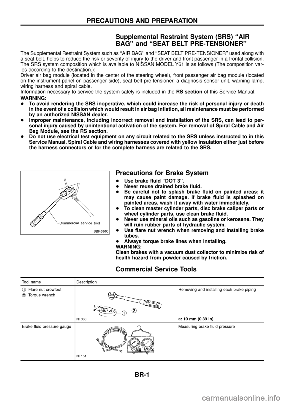
+ Use ¯are nut wrench when removing and installing brake
tubes.
+ Always torque brake lines when installing.
WARNING:
Clean brakes with a vacuum dust collector to minimize risk of
health hazard from powder caused by friction.
Commercial Service Tools
Tool name Description
j
1Flare nut crowfoot
j
2Torque wrench
NT360
Removing and installing each brake piping
a: 10 mm (0.39 in)
Brake ¯uid pressure gauge
NT151
Measuring brake ¯uid pressure
SBR686C
PRECAUTIONS AND PREPARATION
BR-1
Page 4 of 75
NVH Troubleshooting Chart
Use the chart below to help you ®nd the cause of the symptom. If necessary, repair or replace these parts.
Reference page
BR-20, 24, 31BR-31Ð
Ð
Ð
BR-23, 27, 31
BR-23, 27, 31 Ð
Ð
Ð
BR-23, 27 BR-31
NHV in PD section
NHV in PD section
NHV in FA, RA section
NHV in FA section
NHV in FA section
NHV in FA section
NHV in ST section
Possible cause and
SUSPECTED PARTS
Linings or pads - damaged
Linings or pads - uneven wear
Return spring damaged
Shims damaged
Rotor or drum imbalance
Rotor or drum damage
Rotor or drum runout
Rotor or drum deformation
Rotor or drum de¯ection
Rotor or drum rust
Rotor thickness variation
Drum out of round
PROPELLER SHAFT
DIFFERENTIAL
AXLE AND SUSPENSION
TIRES
ROAD WHEEL
AXLE SHAFT
STEERING
Symptom BRAKE Noise
XXXX XXXXXXX
Shake X X X X X X X
Shimmy, Judder X X XXXXXX XXX X
X: Applicable
NOISE, VIBRATION AND HARSHNESS (NVH) TROUBLESHOOTING
BR-2
Page 35 of 75

Purpose
The Anti-Lock Brake System (ABS) consists of electronic and hydraulic components. It allows for control of
braking force so locking of the wheels can be avoided.
The ABS:
1) Improves proper tracking performance through steering wheel operation.
2) Eases obstacle avoidance through steering wheel operation.
3) Improves vehicle stability.
Operation
+When the vehicle speed is less than 10 km/h (6 MPH) this system does not work.
+ The Anti-Lock Brake System (ABS) has a self-test function. The system turns on the ABS warning lamp
for 1 second each time the ignition switch is turned ``ON''. After the engine is started, the ABS warning
lamp turns off. The system performs a test the ®rst time the vehicle reaches 6 km/h (4 MPH). A mechani-
cal noise may be heard as the ABS performs this self-test. This is a normal part of the self-test feature. If
a malfunction is found during this check, the ABS warning lamp will stay on.
+ While driving, a mechanical noise may be heard during ABS operation. This is a normal condition.
+ While DIFF-LOCK is on, the anti-lock brake warning light ¯ashes. This indicates that anti-lock may not be
fully operated. (ABS only)
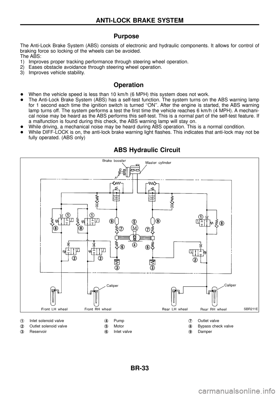
ABS Hydraulic Circuit
j1Inlet solenoid valve
j
2Outlet solenoid valve
j
3Reservoir j
4Pump
j
5Motor
j
6Inlet valve j
7Outlet valve
j
8Bypass check valve
j
9Damper
SBR211E
ANTI-LOCK BRAKE SYSTEM
BR-33