1998 NISSAN PATROL check oil
[x] Cancel search: check oilPage 5 of 75
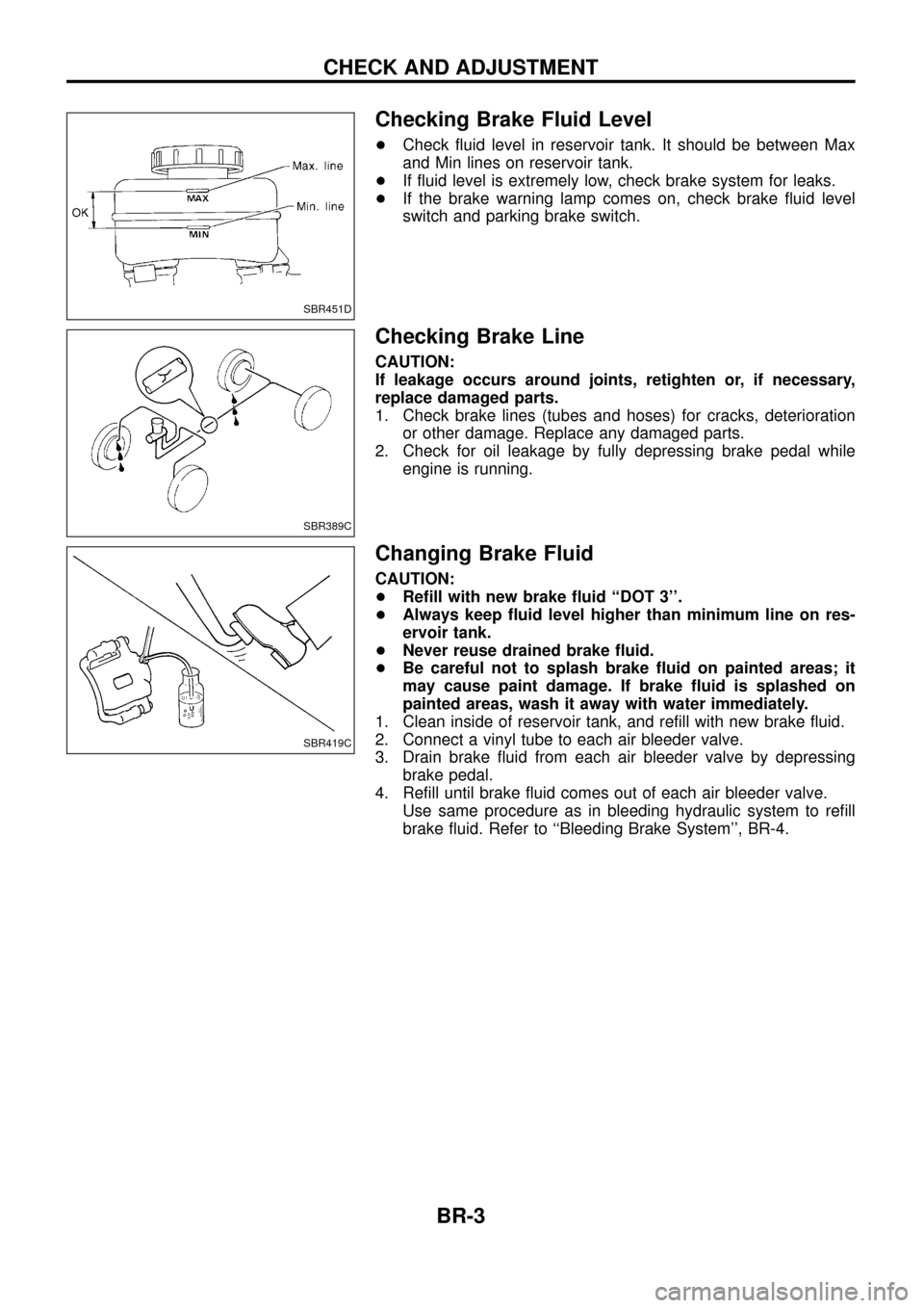
Checking Brake Fluid Level
+Check ¯uid level in reservoir tank. It should be between Max
and Min lines on reservoir tank.
+ If ¯uid level is extremely low, check brake system for leaks.
+ If the brake warning lamp comes on, check brake ¯uid level
switch and parking brake switch.
Checking Brake Line
CAUTION:
If leakage occurs around joints, retighten or, if necessary,
replace damaged parts.
1. Check brake lines (tubes and hoses) for cracks, deterioration
or other damage. Replace any damaged parts.
2. Check for oil leakage by fully depressing brake pedal while engine is running.
Changing Brake Fluid
CAUTION:
+Re®ll with new brake ¯uid ``DOT 3''.
+ Always keep ¯uid level higher than minimum line on res-
ervoir tank.
+ Never reuse drained brake ¯uid.
+ Be careful not to splash brake ¯uid on painted areas; it
may cause paint damage. If brake ¯uid is splashed on
painted areas, wash it away with water immediately.
1. Clean inside of reservoir tank, and re®ll with new brake ¯uid.
2. Connect a vinyl tube to each air bleeder valve.
3. Drain brake ¯uid from each air bleeder valve by depressing brake pedal.
4. Re®ll until brake ¯uid comes out of each air bleeder valve. Use same procedure as in bleeding hydraulic system to re®ll
brake ¯uid. Refer to ``Bleeding Brake System'', BR-4.
SBR451D
SBR389C
SBR419C
CHECK AND ADJUSTMENT
BR-3
Page 9 of 75
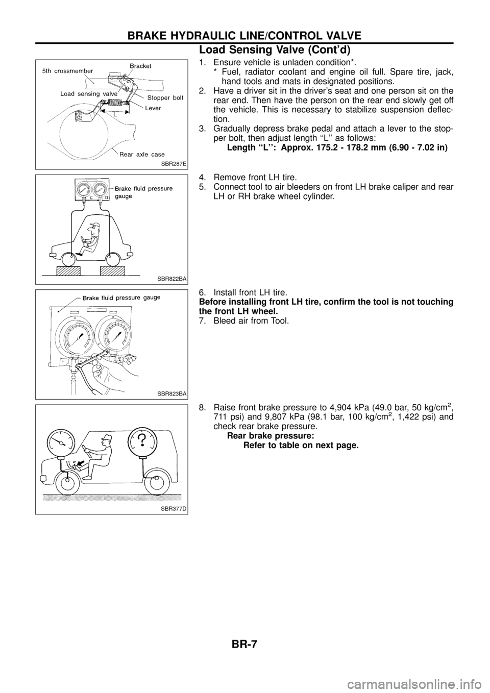
1. Ensure vehicle is unladen condition*.* Fuel, radiator coolant and engine oil full. Spare tire, jack,hand tools and mats in designated positions.
2. Have a driver sit in the driver's seat and one person sit on the rear end. Then have the person on the rear end slowly get off
the vehicle. This is necessary to stabilize suspension de¯ec-
tion.
3. Gradually depress brake pedal and attach a lever to the stop- per bolt, then adjust length ``L'' as follows:Length ``L'': Approx. 175.2 - 178.2 mm (6.90 - 7.02 in)
4. Remove front LH tire.
5. Connect tool to air bleeders on front LH brake caliper and rear LH or RH brake wheel cylinder.
6. Install front LH tire.
Before installing front LH tire, con®rm the tool is not touching
the front LH wheel.
7. Bleed air from Tool.
8. Raise front brake pressure to 4,904 kPa (49.0 bar, 50 kg/cm
2,
711 psi) and 9,807 kPa (98.1 bar, 100 kg/cm2, 1,422 psi) and
check rear brake pressure. Rear brake pressure: Refer to table on next page.
SBR287E
SBR822BA
SBR823BA
SBR377D
BRAKE HYDRAULIC LINE/CONTROL VALVE
Load Sensing Valve (Cont'd)
BR-7
Page 21 of 75
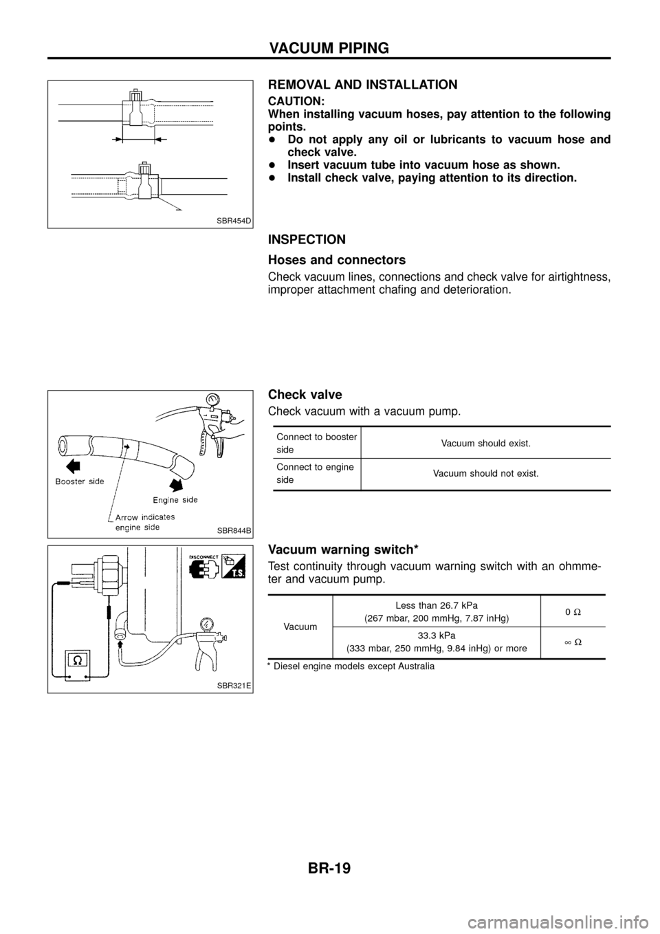
REMOVAL AND INSTALLATION
CAUTION:
When installing vacuum hoses, pay attention to the following
points.
+Do not apply any oil or lubricants to vacuum hose and
check valve.
+ Insert vacuum tube into vacuum hose as shown.
+ Install check valve, paying attention to its direction.
INSPECTION
Hoses and connectors
Check vacuum lines, connections and check valve for airtightness,
improper attachment cha®ng and deterioration.
Check valve
Check vacuum with a vacuum pump.
Connect to booster
side Vacuum should exist.
Connect to engine
side Vacuum should not exist.
Vacuum warning switch*
Test continuity through vacuum warning switch with an ohmme-
ter and vacuum pump.
VacuumLess than 26.7 kPa
(267 mbar, 200 mmHg, 7.87 inHg) 0
W
33.3 kPa
(333 mbar, 250 mmHg, 9.84 inHg) or more ¥W
* Diesel engine models except Australia
SBR454D
SBR844B
SBR321E
VACUUM PIPING
BR-19
Page 25 of 75
Removal
WARNING:
Clean brake pads with a vacuum dust collector to minimize the
hazard of airborne particles or other materials.
CAUTION:
Suspend caliper assembly with wire so as not to stretch brake
hose.
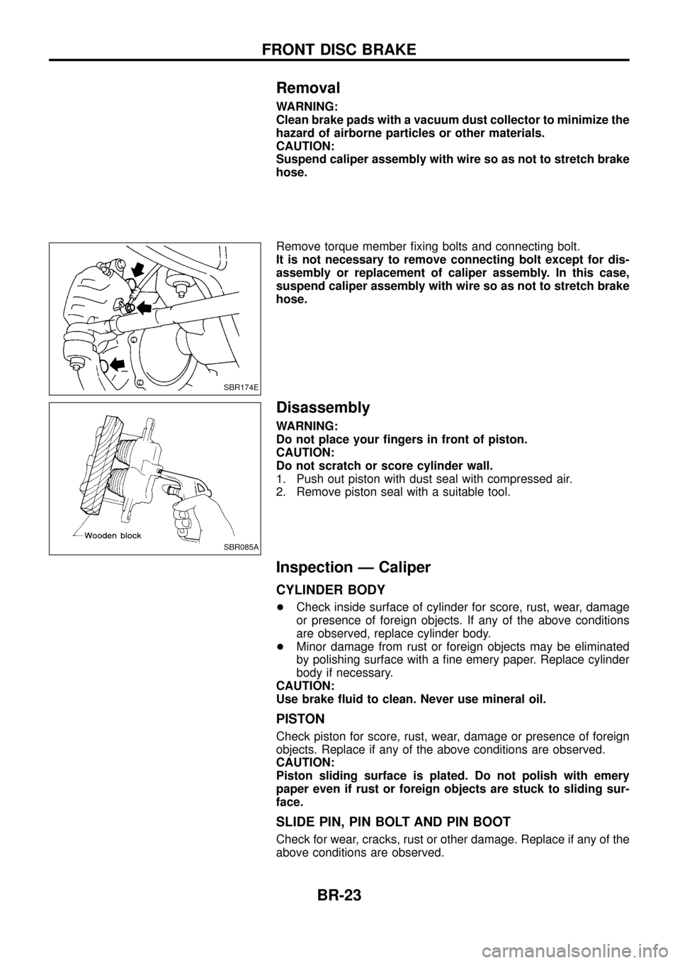
Remove torque member ®xing bolts and connecting bolt.
It is not necessary to remove connecting bolt except for dis-
assembly or replacement of caliper assembly. In this case,
suspend caliper assembly with wire so as not to stretch brake
hose.
Disassembly
WARNING:
Do not place your ®ngers in front of piston.
CAUTION:
Do not scratch or score cylinder wall.
1. Push out piston with dust seal with compressed air.
2. Remove piston seal with a suitable tool.
Inspection Ð Caliper
CYLINDER BODY
+Check inside surface of cylinder for score, rust, wear, damage
or presence of foreign objects. If any of the above conditions
are observed, replace cylinder body.
+ Minor damage from rust or foreign objects may be eliminated
by polishing surface with a ®ne emery paper. Replace cylinder
body if necessary.
CAUTION:
Use brake ¯uid to clean. Never use mineral oil.
PISTON
Check piston for score, rust, wear, damage or presence of foreign
objects. Replace if any of the above conditions are observed.
CAUTION:
Piston sliding surface is plated. Do not polish with emery
paper even if rust or foreign objects are stuck to sliding sur-
face.
SLIDE PIN, PIN BOLT AND PIN BOOT
Check for wear, cracks, rust or other damage. Replace if any of the
above conditions are observed.
SBR174E
SBR085A
FRONT DISC BRAKE
BR-23
Page 29 of 75
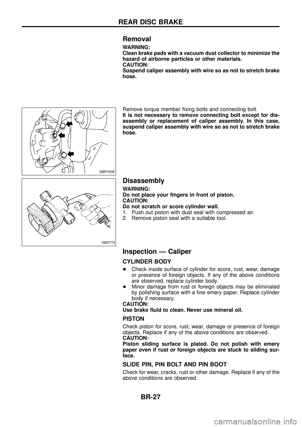
Removal
WARNING:
Clean brake pads with a vacuum dust collector to minimize the
hazard of airborne particles or other materials.
CAUTION:
Suspend caliper assembly with wire so as not to stretch brake
hose.
Remove torque member ®xing bolts and connecting bolt.
It is not necessary to remove connecting bolt except for dis-
assembly or replacement of caliper assembly. In this case,
suspend caliper assembly with wire so as not to stretch brake
hose.
Disassembly
WARNING:
Do not place your ®ngers in front of piston.
CAUTION:
Do not scratch or score cylinder wall.
1. Push out piston with dust seal with compressed air.
2. Remove piston seal with a suitable tool.
Inspection Ð Caliper
CYLINDER BODY
+Check inside surface of cylinder for score, rust, wear, damage
or presence of foreign objects. If any of the above conditions
are observed, replace cylinder body.
+ Minor damage from rust or foreign objects may be eliminated
by polishing surface with a ®ne emery paper. Replace cylinder
body if necessary.
CAUTION:
Use brake ¯uid to clean. Never use mineral oil.
PISTON
Check piston for score, rust, wear, damage or presence of foreign
objects. Replace if any of the above conditions are observed.
CAUTION:
Piston sliding surface is plated. Do not polish with emery
paper even if rust or foreign objects are stuck to sliding sur-
face.
SLIDE PIN, PIN BOLT AND PIN BOOT
Check for wear, cracks, rust or other damage. Replace if any of the
above conditions are observed.
SBR183E
SBR772
REAR DISC BRAKE
BR-27
Page 51 of 75
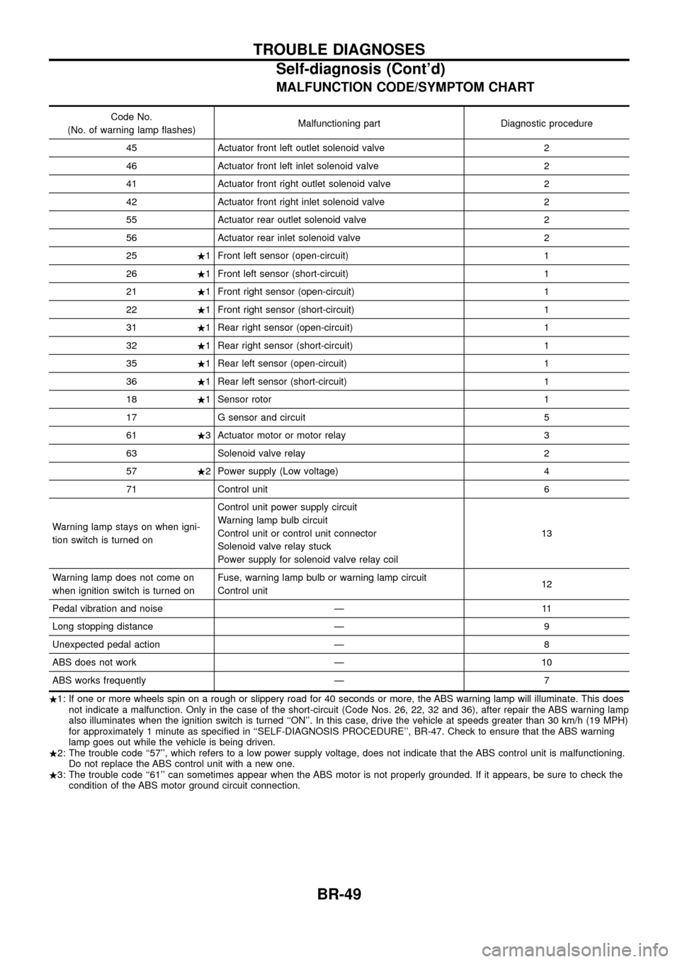
MALFUNCTION CODE/SYMPTOM CHART
Code No.
(No. of warning lamp ¯ashes) Malfunctioning part Diagnostic procedure
45 Actuator front left outlet solenoid valve 2
46 Actuator front left inlet solenoid valve 2
41 Actuator front right outlet solenoid valve 2
42 Actuator front right inlet solenoid valve 2
55 Actuator rear outlet solenoid valve 2
56 Actuator rear inlet solenoid valve 2
25 .1 Front left sensor (open-circuit) 1
26 .1 Front left sensor (short-circuit) 1
21 .1 Front right sensor (open-circuit) 1
22 .1 Front right sensor (short-circuit) 1
31 .1 Rear right sensor (open-circuit) 1
32 .1 Rear right sensor (short-circuit) 1
35 .1 Rear left sensor (open-circuit) 1
36 .1 Rear left sensor (short-circuit) 1
18 .1 Sensor rotor 1
17 G sensor and circuit 5
61 .3 Actuator motor or motor relay 3
63 Solenoid valve relay 2
57 .2 Power supply (Low voltage) 4
71 Control unit 6
Warning lamp stays on when igni-
tion switch is turned on Control unit power supply circuit
Warning lamp bulb circuit
Control unit or control unit connector
Solenoid valve relay stuck
Power supply for solenoid valve relay coil
13
Warning lamp does not come on
when ignition switch is turned on Fuse, warning lamp bulb or warning lamp circuit
Control unit
12
Pedal vibration and noise Ð 11
Long stopping distance Ð 9
Unexpected pedal action Ð 8
ABS does not work Ð 10
ABS works frequently Ð 7
. 1: If one or more wheels spin on a rough or slippery road for 40 seconds or more, the ABS warning lamp will illuminate. This does
not indicate a malfunction. Only in the case of the short-circuit (Code Nos. 26, 22, 32 and 36), after repair the ABS warning lamp
also illuminates when the ignition switch is turned ``ON''. In this case, drive the vehicle at speeds greater than 30 km/h (19 MPH)
for approximately 1 minute as speci®ed in ``SELF-DIAGNOSIS PROCEDURE'', BR-47. Check to ensure that the ABS warning
lamp goes out while the vehicle is being driven.
. 2: The trouble code ``57'', which refers to a low power supply voltage, does not indicate that the ABS control unit is malfunctioning.
Do not replace the ABS control unit with a new one.
. 3: The trouble code ``61'' can sometimes appear when the ABS motor is not properly grounded. If it appears, be sure to check the
condition of the ABS motor ground circuit connection.
TROUBLE DIAGNOSES
Self-diagnosis (Cont'd)
BR-49