Page 8 of 75

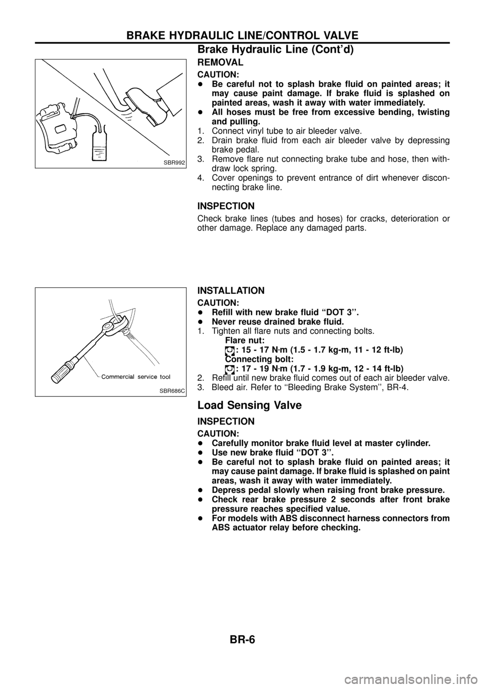
REMOVAL
CAUTION:
+Be careful not to splash brake ¯uid on painted areas; it
may cause paint damage. If brake ¯uid is splashed on
painted areas, wash it away with water immediately.
+ All hoses must be free from excessive bending, twisting
and pulling.
1. Connect vinyl tube to air bleeder valve.
2. Drain brake ¯uid from each air bleeder valve by depressing brake pedal.
3. Remove ¯are nut connecting brake tube and hose, then with- draw lock spring.
4. Cover openings to prevent entrance of dirt whenever discon- necting brake line.
INSPECTION
Check brake lines (tubes and hoses) for cracks, deterioration or
other damage. Replace any damaged parts.
INSTALLATION
CAUTION:
+Re®ll with new brake ¯uid ``DOT 3''.
+ Never reuse drained brake ¯uid.
1. Tighten all ¯are nuts and connecting bolts. Flare nut:
:15-17N zm (1.5 - 1.7 kg-m, 11 - 12 ft-lb)
Connecting bolt:
:17-19N zm (1.7 - 1.9 kg-m, 12 - 14 ft-lb)
2. Re®ll until new brake ¯uid comes out of each air bleeder valve.
3. Bleed air. Refer to ``Bleeding Brake System'', BR-4.
Load Sensing Valve
INSPECTION
CAUTION:
+ Carefully monitor brake ¯uid level at master cylinder.
+ Use new brake ¯uid ``DOT 3''.
+ Be careful not to splash brake ¯uid on painted areas; it
may cause paint damage. If brake ¯uid is splashed on paint
areas, wash it away with water immediately.
+ Depress pedal slowly when raising front brake pressure.
+ Check rear brake pressure 2 seconds after front brake
pressure reaches speci®ed value.
+ For models with ABS disconnect harness connectors from
ABS actuator relay before checking.
SBR992
SBR686C
BRAKE HYDRAULIC LINE/CONTROL VALVE
Brake Hydraulic Line (Cont'd)
BR-6
Page 17 of 75

Brake Booster
ON-VEHICLE SERVICE
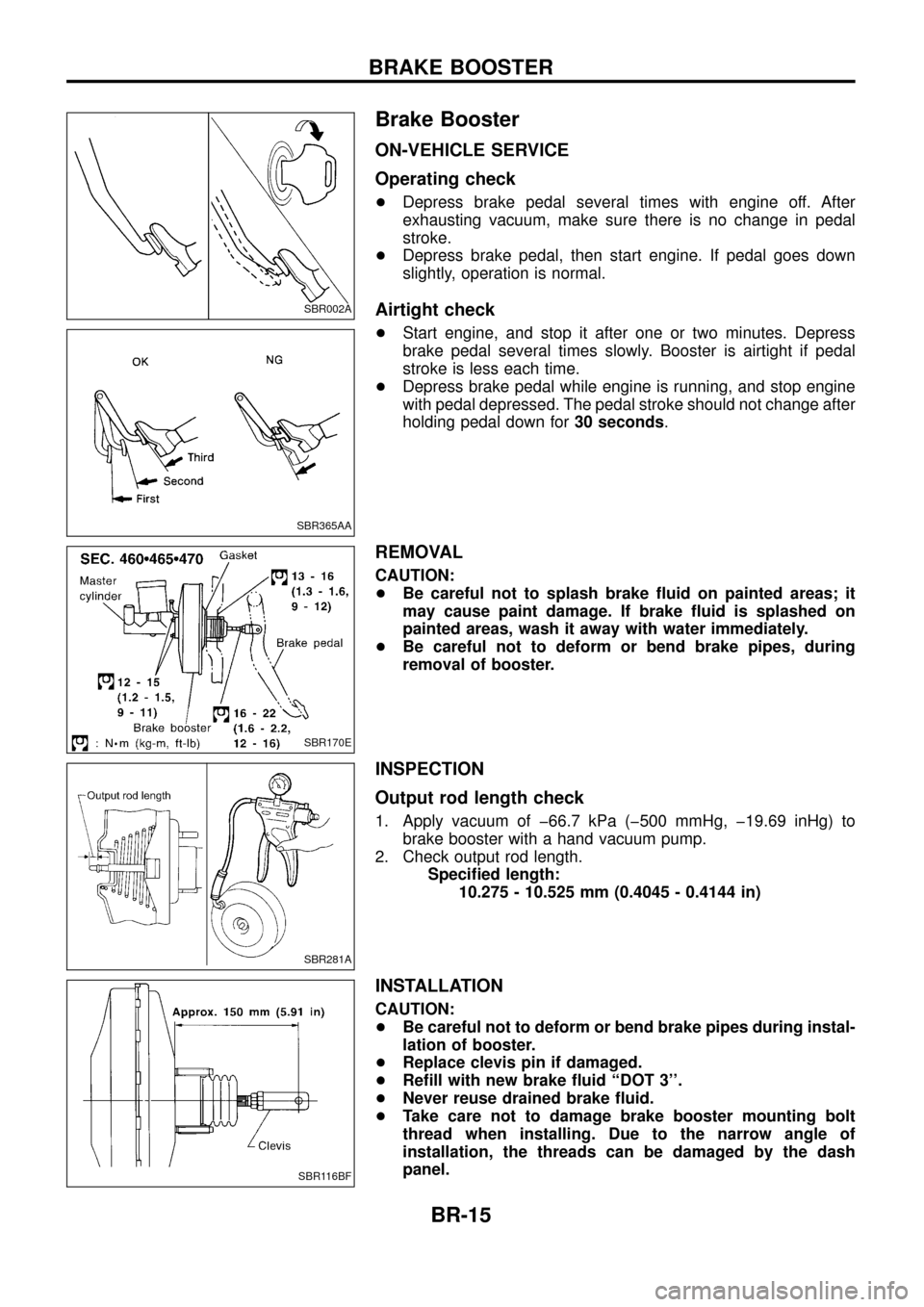
Operating check
+Depress brake pedal several times with engine off. After
exhausting vacuum, make sure there is no change in pedal
stroke.
+ Depress brake pedal, then start engine. If pedal goes down
slightly, operation is normal.
Airtight check
+Start engine, and stop it after one or two minutes. Depress
brake pedal several times slowly. Booster is airtight if pedal
stroke is less each time.
+ Depress brake pedal while engine is running, and stop engine
with pedal depressed. The pedal stroke should not change after
holding pedal down for 30 seconds.
REMOVAL
CAUTION:
+Be careful not to splash brake ¯uid on painted areas; it
may cause paint damage. If brake ¯uid is splashed on
painted areas, wash it away with water immediately.
+ Be careful not to deform or bend brake pipes, during
removal of booster.
INSPECTION
Output rod length check
1. Apply vacuum of þ66.7 kPa (þ500 mmHg, þ19.69 inHg) to
brake booster with a hand vacuum pump.
2. Check output rod length. Speci®ed length:10.275 - 10.525 mm (0.4045 - 0.4144 in)
INSTALLATION
CAUTION:
+Be careful not to deform or bend brake pipes during instal-
lation of booster.
+ Replace clevis pin if damaged.
+ Re®ll with new brake ¯uid ``DOT 3''.
+ Never reuse drained brake ¯uid.
+ Take care not to damage brake booster mounting bolt
thread when installing. Due to the narrow angle of
installation, the threads can be damaged by the dash
panel.
SBR002A
SBR365AA
SBR170E
SBR281A
SBR116BF
BRAKE BOOSTER
BR-15
Page 26 of 75

Inspection Ð Rotor
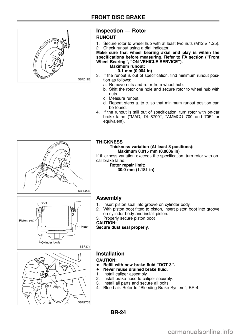
RUNOUT
1. Secure rotor to wheel hub with at least two nuts (M12 ý 1.25).
2. Check runout using a dial indicator.
Make sure that wheel bearing axial end play is within the
speci®cations before measuring. Refer to FA section (``Front
Wheel Bearing'', ``ON-VEHICLE SERVICE'').Maximum runout:0.1 mm (0.004 in)
3. If the runout is out of speci®cation, ®nd minimum runout posi- tion as follows:
a. Remove nuts and rotor from wheel hub.
b. Shift the rotor one hole and secure rotor to wheel hub withnuts.
c. Measure runout.
d. Repeat steps a. to c. so that minimum runout position can be found.
4. If the runout is still out of speci®cation, turn rotor with on-car brake lathe (``MAD, DL-8700'', ``AMMCO 700 and 705'' or
equivalent).
THICKNESS
Thickness variation (At least 8 positions): Maximum 0.015 mm (0.0006 in)
If thickness variation exceeds the speci®cation, turn rotor with on-
car brake lathe. Rotor repair limit:30.0 mm (1.181 in)
Assembly
1. Insert piston seal into groove on cylinder body.
2. With piston boot ®tted to piston, insert piston boot into grooveon cylinder body and install piston.
3. Properly secure piston boot
CAUTION:
Secure dust seal properly.
Installation
CAUTION:
+ Re®ll with new brake ¯uid ``DOT 3''.
+ Never reuse drained brake ¯uid.
1. Install caliper assembly.
2. Install brake hose to caliper securely.
3. Install all parts and secure all bolts.
4. Bleed air. Refer to ``Bleeding Brake System'', BR-4.
SBR019B
SBR020B
SBR574
SBR175E
FRONT DISC BRAKE
BR-24
Page 30 of 75

Inspection Ð Rotor
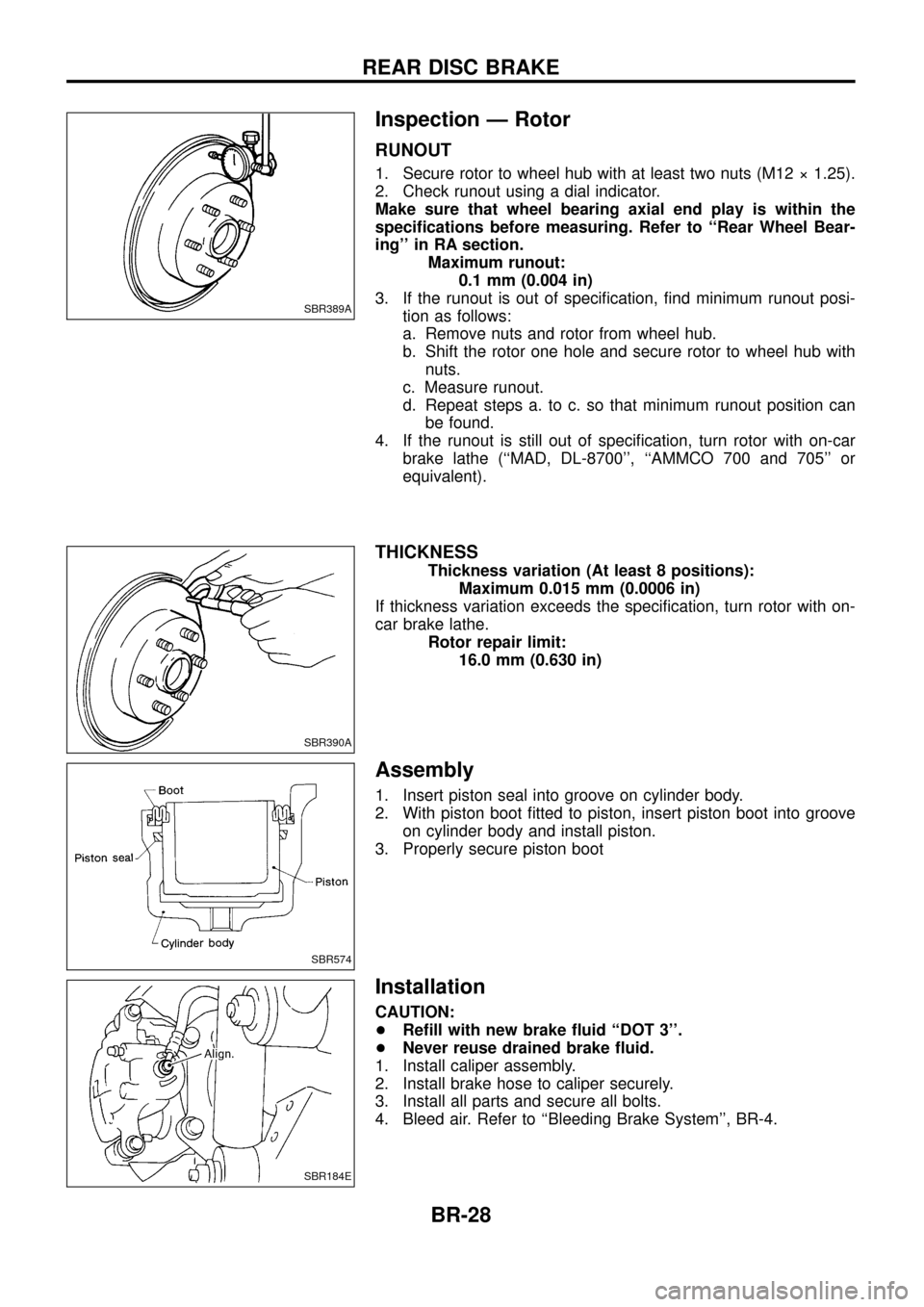
RUNOUT
1. Secure rotor to wheel hub with at least two nuts (M12 ý 1.25).
2. Check runout using a dial indicator.
Make sure that wheel bearing axial end play is within the
speci®cations before measuring. Refer to ``Rear Wheel Bear-
ing'' in RA section.Maximum runout:0.1 mm (0.004 in)
3. If the runout is out of speci®cation, ®nd minimum runout posi- tion as follows:
a. Remove nuts and rotor from wheel hub.
b. Shift the rotor one hole and secure rotor to wheel hub withnuts.
c. Measure runout.
d. Repeat steps a. to c. so that minimum runout position can be found.
4. If the runout is still out of speci®cation, turn rotor with on-car brake lathe (``MAD, DL-8700'', ``AMMCO 700 and 705'' or
equivalent).
THICKNESS
Thickness variation (At least 8 positions): Maximum 0.015 mm (0.0006 in)
If thickness variation exceeds the speci®cation, turn rotor with on-
car brake lathe. Rotor repair limit:16.0 mm (0.630 in)
Assembly
1. Insert piston seal into groove on cylinder body.
2. With piston boot ®tted to piston, insert piston boot into grooveon cylinder body and install piston.
3. Properly secure piston boot
Installation
CAUTION:
+ Re®ll with new brake ¯uid ``DOT 3''.
+ Never reuse drained brake ¯uid.
1. Install caliper assembly.
2. Install brake hose to caliper securely.
3. Install all parts and secure all bolts.
4. Bleed air. Refer to ``Bleeding Brake System'', BR-4.
SBR389A
SBR390A
SBR574
SBR184E
REAR DISC BRAKE
BR-28
Page 40 of 75
ABS ACTUATOR AND ELECTRIC UNIT
Removal
1. Disconnect battery cable.
2. Drain brake ¯uid. Refer to ``Changing Brake Fluid'', BR-3.
3. Remove mounting bracket ®xing bolts and nuts.
4. Disconnect connector, brake pipes and remove ®xing nuts.
Installation
CAUTION:
After installation, re®ll brake ¯uid. Then bleed air. Refer to
Bleeding Brake System'', BR-4.
1. Connect brake pipes temporarily.
2. Tighten ®xing bolts and nuts.
3. Tighten brake pipes.
4. Connect connector and battery cable.
SBR191E
ANTI-LOCK BRAKE SYSTEM
Removal and Installation (Cont'd)BR-38