1998 NISSAN PATROL sensor
[x] Cancel search: sensorPage 51 of 75
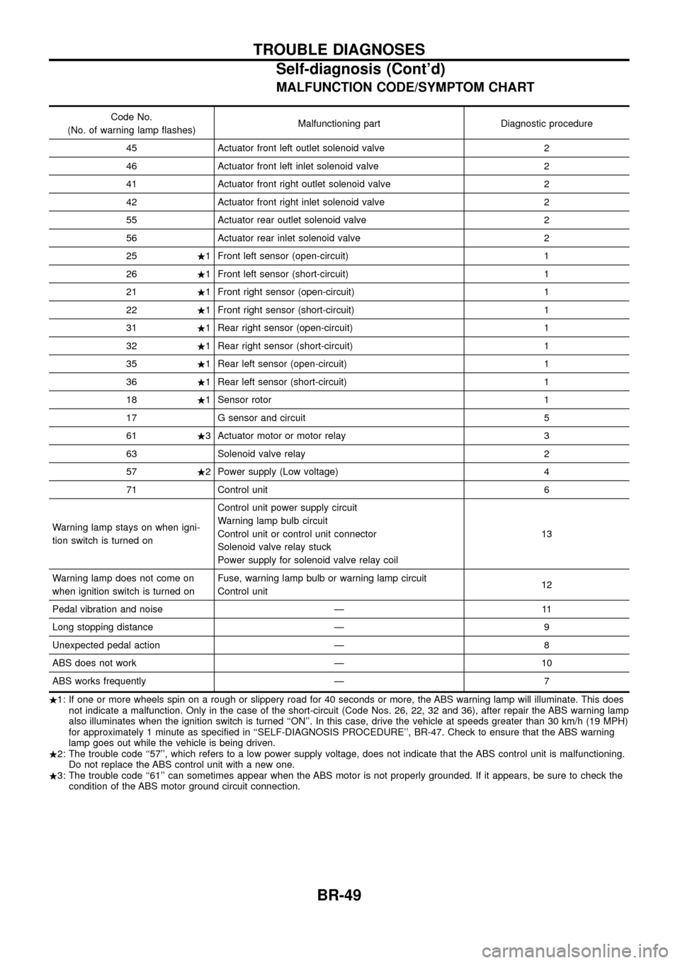
MALFUNCTION CODE/SYMPTOM CHART
Code No.
(No. of warning lamp ¯ashes) Malfunctioning part Diagnostic procedure
45 Actuator front left outlet solenoid valve 2
46 Actuator front left inlet solenoid valve 2
41 Actuator front right outlet solenoid valve 2
42 Actuator front right inlet solenoid valve 2
55 Actuator rear outlet solenoid valve 2
56 Actuator rear inlet solenoid valve 2
25 .1 Front left sensor (open-circuit) 1
26 .1 Front left sensor (short-circuit) 1
21 .1 Front right sensor (open-circuit) 1
22 .1 Front right sensor (short-circuit) 1
31 .1 Rear right sensor (open-circuit) 1
32 .1 Rear right sensor (short-circuit) 1
35 .1 Rear left sensor (open-circuit) 1
36 .1 Rear left sensor (short-circuit) 1
18 .1 Sensor rotor 1
17 G sensor and circuit 5
61 .3 Actuator motor or motor relay 3
63 Solenoid valve relay 2
57 .2 Power supply (Low voltage) 4
71 Control unit 6
Warning lamp stays on when igni-
tion switch is turned on Control unit power supply circuit
Warning lamp bulb circuit
Control unit or control unit connector
Solenoid valve relay stuck
Power supply for solenoid valve relay coil
13
Warning lamp does not come on
when ignition switch is turned on Fuse, warning lamp bulb or warning lamp circuit
Control unit
12
Pedal vibration and noise Ð 11
Long stopping distance Ð 9
Unexpected pedal action Ð 8
ABS does not work Ð 10
ABS works frequently Ð 7
. 1: If one or more wheels spin on a rough or slippery road for 40 seconds or more, the ABS warning lamp will illuminate. This does
not indicate a malfunction. Only in the case of the short-circuit (Code Nos. 26, 22, 32 and 36), after repair the ABS warning lamp
also illuminates when the ignition switch is turned ``ON''. In this case, drive the vehicle at speeds greater than 30 km/h (19 MPH)
for approximately 1 minute as speci®ed in ``SELF-DIAGNOSIS PROCEDURE'', BR-47. Check to ensure that the ABS warning
lamp goes out while the vehicle is being driven.
. 2: The trouble code ``57'', which refers to a low power supply voltage, does not indicate that the ABS control unit is malfunctioning.
Do not replace the ABS control unit with a new one.
. 3: The trouble code ``61'' can sometimes appear when the ABS motor is not properly grounded. If it appears, be sure to check the
condition of the ABS motor ground circuit connection.
TROUBLE DIAGNOSES
Self-diagnosis (Cont'd)
BR-49
Page 52 of 75
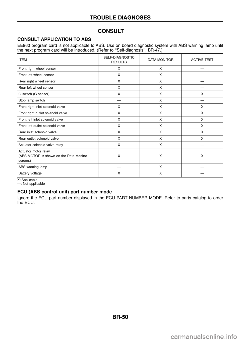
CONSULT
CONSULT APPLICATION TO ABS
EE960 program card is not applicable to ABS. Use on board diagnostic system with ABS warning lamp until
the next program card will be introduced. (Refer to ``Self-diagnosis'', BR-47.)
ITEMSELF-DIAGNOSTIC
RESULTS DATA MONITOR ACTIVE TEST
Front right wheel sensor X X Ð
Front left wheel sensor X X Ð
Rear right wheel sensor X X Ð
Rear left wheel sensor X X Ð
G switch (G sensor) X X X
Stop lamp switch Ð X Ð
Front right inlet solenoid valve X X X
Front right outlet solenoid valve X X X
Front left inlet solenoid valve X X X
Front left outlet solenoid valve X X X
Rear inlet solenoid valve X X X
Rear outlet solenoid valve X X X
Actuator solenoid valve relay X X Ð
Actuator motor relay
(ABS MOTOR is shown on the Data Monitor
screen.) XXX
ABS warning lamp Ð X Ð
Battery voltage X X Ð
X: Applicable
Ð: Not applicable
ECU (ABS control unit) part number mode
Ignore the ECU part number displayed in the ECU PART NUMBER MODE. Refer to parts catalog to order
the ECU.
TROUBLE DIAGNOSES
BR-50
Page 54 of 75
![NISSAN PATROL 1998 Y61 / 5.G Brake System Workshop Manual SELF-DIAGNOSTIC RESULTS MODE
Diagnostic item Diagnostic item is detected when ...Diagnostic
procedure
FR RH SENSOR .1
[OPEN] +
Circuit for front right wheel sensor is open.
(An abnormally high input v NISSAN PATROL 1998 Y61 / 5.G Brake System Workshop Manual SELF-DIAGNOSTIC RESULTS MODE
Diagnostic item Diagnostic item is detected when ...Diagnostic
procedure
FR RH SENSOR .1
[OPEN] +
Circuit for front right wheel sensor is open.
(An abnormally high input v](/manual-img/5/614/w960_614-53.png)
SELF-DIAGNOSTIC RESULTS MODE
Diagnostic item Diagnostic item is detected when ...Diagnostic
procedure
FR RH SENSOR .1
[OPEN] +
Circuit for front right wheel sensor is open.
(An abnormally high input voltage is entered.) 1
FR LH SENSOR .1
[OPEN] +
Circuit for front left wheel sensor is open.
(An abnormally high input voltage is entered.) 1
RR RH SENSOR .1
[OPEN] +
Circuit for rear right sensor is open.
(An abnormally high input voltage is entered.) 1
RR LH SENSOR .1
[OPEN] +
Circuit for rear left sensor is open.
(An abnormally high input voltage is entered.) 1
FR RH SENSOR .1
[SHORT] +
Circuit for front right wheel sensor is shorted.
(An abnormally low input voltage is entered.) 1
FR LH SENSOR .1
[SHORT] +
Circuit for front left wheel sensor is shorted.
(An abnormally low input voltage is entered.) 1
RR RH SENSOR .1
[SHORT] +
Circuit for rear right sensor is shorted.
(An abnormally low input voltage is entered.) 1
RR LH SENSOR .1
[SHORT] +
Circuit for rear left sensor is shorted.
(An abnormally low input voltage is entered.) 1
ABS SENSOR .1
[ABNORMAL SIGNAL] +
Teeth damage on sensor rotor or improper installation of wheel sensor.
(Abnormal wheel sensor signal is entered.) 1
FR RH IN ABS SOL
[OPEN] +
Circuit for front right inlet solenoid valve is open.
(An abnormally low output voltage is entered.) 2
FR LH IN ABS SOL
[OPEN] +
Circuit for front left inlet solenoid valve is open.
(An abnormally low output voltage is entered.) 2
RR IN ABS SOL
[OPEN] +
Circuit for rear inlet solenoid valve is open.
(An abnormally low output voltage is entered.) 2
FR RH IN ABS SOL
[SHORT] +
Circuit for front right inlet solenoid valve is shorted.
(An abnormally high output voltage is entered.) 2
FR LH IN ABS SOL
[SHORT] +
Circuit for front left inlet solenoid valve is shorted.
(An abnormally high output voltage is entered.) 2
RR IN ABS SOL
[SHORT] +
Circuit for rear inlet solenoid valve is shorted.
(An abnormally high output voltage is entered.) 2
FR RH OUT ABS SOL
[OPEN] +
Circuit for front right outlet solenoid valve is open.
(An abnormally low output voltage is entered.) 2
FR LH OUT ABS SOL
[OPEN] +
Circuit for front left outlet solenoid valve is open.
(An abnormally low output voltage is entered.) 2
RR OUT ABS SOL
[OPEN] +
Circuit for rear outlet solenoid valve is open.
(An abnormally low output voltage is entered.) 2
FR RH OUT ABS SOL
[SHORT] +
Circuit for front right outlet solenoid valve is shorted.
(An abnormally high output voltage is entered.) 2
FR LH OUT ABS SOL
[SHORT] +
Circuit for front left outlet solenoid valve is shorted.
(An abnormally high output voltage is entered.) 2
RR OUT ABS SOL
[SHORT] +
Circuit for rear outlet solenoid valve is shorted.
(An abnormally high output voltage is entered.) 2
ABS ACTUATOR RELAY
[ABNORMAL] +
Actuator solenoid valve relay is ON, even if control unit sends off signal.
+ Actuator solenoid valve relay is OFF, even if control unit sends on signal. 2
ABS MOTOR RELAY
[ABNORMAL] +
Circuit for ABS motor relay is open or shorted.
+ Circuit for actuator motor is open or shorted.
+ Actuator motor relay is stuck. 3
BATTERY VOLT
[VB-LOW] +
Power source voltage supplied to ABS control unit is abnormally low. 4
CONTROL UNIT +Function of calculation in ABS control unit has failed. 6
G-SENSOR
[ABNORMAL] +
G sensor circuit is open or shorted. 5
. 1: If one or more wheels spin on a rough or slippery road for 40 seconds or more, the ABS warning lamp will illuminate. This does
not indicate a malfunction. Only in the case of the short-circuit (Code Nos. 26, 22, 32 and 36), after repair the ABS warning
lamp also illuminates when the ignition switch is turned ``ON''. In this case, drive the vehicle at speeds greater than 30 km/h (19
MPH) for approximately 1 minute as speci®ed in ``SELF-DIAGNOSIS PROCEDURE'', BR-47. Check to ensure that the ABS
warning lamp goes out while the vehicle is being driven.
TROUBLE DIAGNOSES
CONSULT Inspection Procedure (Cont'd)
BR-52
Page 57 of 75
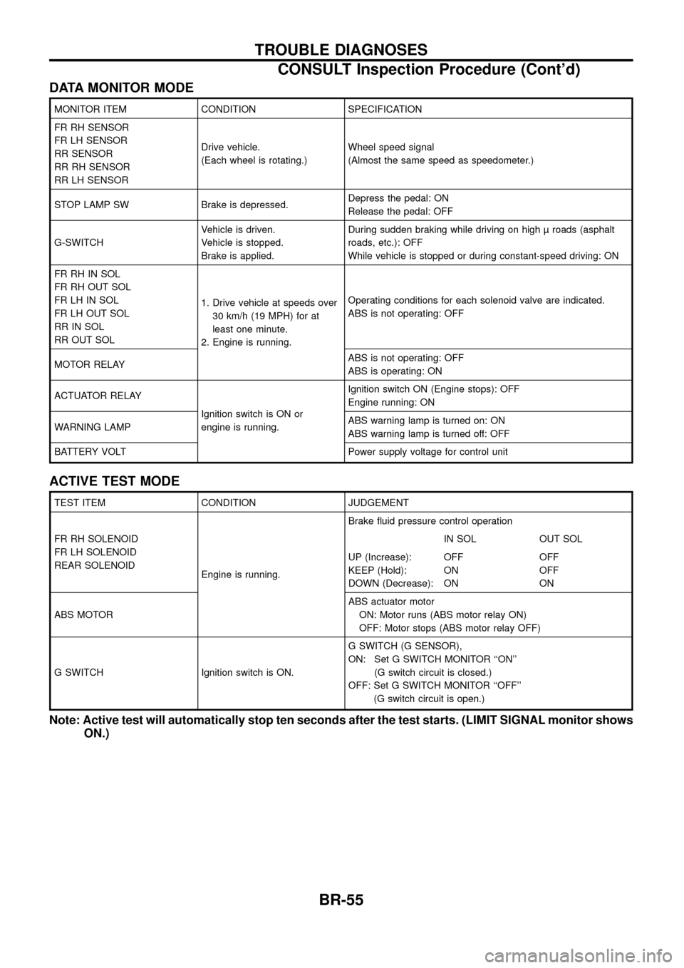
DATA MONITOR MODE
MONITOR ITEM CONDITION SPECIFICATION
FR RH SENSOR
FR LH SENSOR
RR SENSOR
RR RH SENSOR
RR LH SENSORDrive vehicle.
(Each wheel is rotating.)
Wheel speed signal
(Almost the same speed as speedometer.)
STOP LAMP SW Brake is depressed. Depress the pedal: ON
Release the pedal: OFF
G-SWITCH Vehicle is driven.
Vehicle is stopped.
Brake is applied.During sudden braking while driving on high roads (asphalt
roads, etc.): OFF
While vehicle is stopped or during constant-speed driving: ON
FR RH IN SOL
FR RH OUT SOL
FR LH IN SOL
FR LH OUT SOL
RR IN SOL
RR OUT SOL 1. Drive vehicle at speeds over
30 km/h (19 MPH) for at
least one minute.
2. Engine is running. Operating conditions for each solenoid valve are indicated.
ABS is not operating: OFF
MOTOR RELAY ABS is not operating: OFF
ABS is operating: ON
ACTUATOR RELAY Ignition switch is ON or
engine is running.Ignition switch ON (Engine stops): OFF
Engine running: ON
WARNING LAMP ABS warning lamp is turned on: ON
ABS warning lamp is turned off: OFF
BATTERY VOLT Power supply voltage for control unit
ACTIVE TEST MODE
TEST ITEM CONDITION JUDGEMENT
FR RH SOLENOID
FR LH SOLENOID
REAR SOLENOID Engine is running.Brake ¯uid pressure control operation
IN SOL OUT SOL
UP (Increase):
KEEP (Hold):
DOWN (Decrease): OFF
ON
ONOFF
OFF
ON
ABS MOTOR ABS actuator motor
ON: Motor runs (ABS motor relay ON)
OFF: Motor stops (ABS motor relay OFF)
G SWITCH Ignition switch is ON. G SWITCH (G SENSOR),
ON: Set G SWITCH MONITOR ``ON''
(G switch circuit is closed.)
OFF: Set G SWITCH MONITOR ``OFF'' (G switch circuit is open.)
Note: Active test will automatically stop ten seconds after the test starts. (LIMIT SIGNAL monitor shows ON.)
TROUBLE DIAGNOSES
CONSULT Inspection Procedure (Cont'd)
BR-55
Page 59 of 75
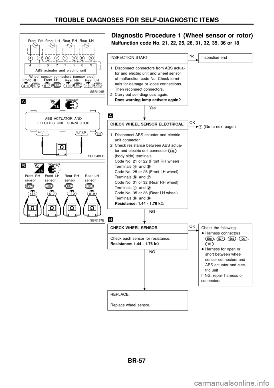
Diagnostic Procedure 1 (Wheel sensor or rotor)
Malfunction code No. 21, 22, 25, 26, 31, 32, 35, 36 or 18
INSPECTION START
- ---------------------------------------------------------------------------------------------------------------------------------------------------------------------------------------------------------------------------------------------------------------------------------------------------------------
1. Disconnect connectors from ABS actua- tor and electric unit and wheel sensor
of malfunction code No. Check termi-
nals for damage or loose connections.
Then reconnect connectors.
2. Carry out self-diagnosis again. Does warning lamp activate again?
Ye s
cNo Inspection end
CHECK WHEEL SENSOR ELECTRICAL.
- ---------------------------------------------------------------------------------------------------------------------------------------------------------------------------------------------------------------------------------------------------------------------------------------------------------------
1. Disconnect ABS actuator and electric unit connector.
2. Check resistance between ABS actua- tor and electric unit connector
E18
(body side) terminals.
Code No. 21 or 22 (Front RH wheel)
Terminals j
4andj5
Code No. 25 or 26 (Front LH wheel)
Terminals j
6andj7
Code No. 31 or 32 (Rear RH wheel)
Terminals j
1andj2
Code No. 35 or 36 (Rear LH wheel)
Terminals j
8andj9
Resistance: 1.44 - 1.76 k
W
NG
cOK
jA(Go to next page.)
CHECK WHEEL SENSOR.
- ---------------------------------------------------------------------------------------------------------------------------------------------------------------------------------------------------------------------------------------------------------------------------------------------------------------
Check each sensor for resistance.
Resistance: 1.44 - 1.76 k W
NG
cOK
Check the following.
+Harness connectors
E18,E77,E62,C6,
C5
+Harness for open or
short between wheel
sensor connectors and
ABS actuator and elec-
tric unit
If NG, repair harness or
connectors.
REPLACE.
- ---------------------------------------------------------------------------------------------------------------------------------------------------------------------------------------------------------------------------------------------------------------------------------------------------------------
Replace wheel sensor.
SBR196E
SBR048EB
SBR197E
.
.
.
TROUBLE DIAGNOSES FOR SELF-DIAGNOSTIC ITEMS
BR-57
Page 60 of 75
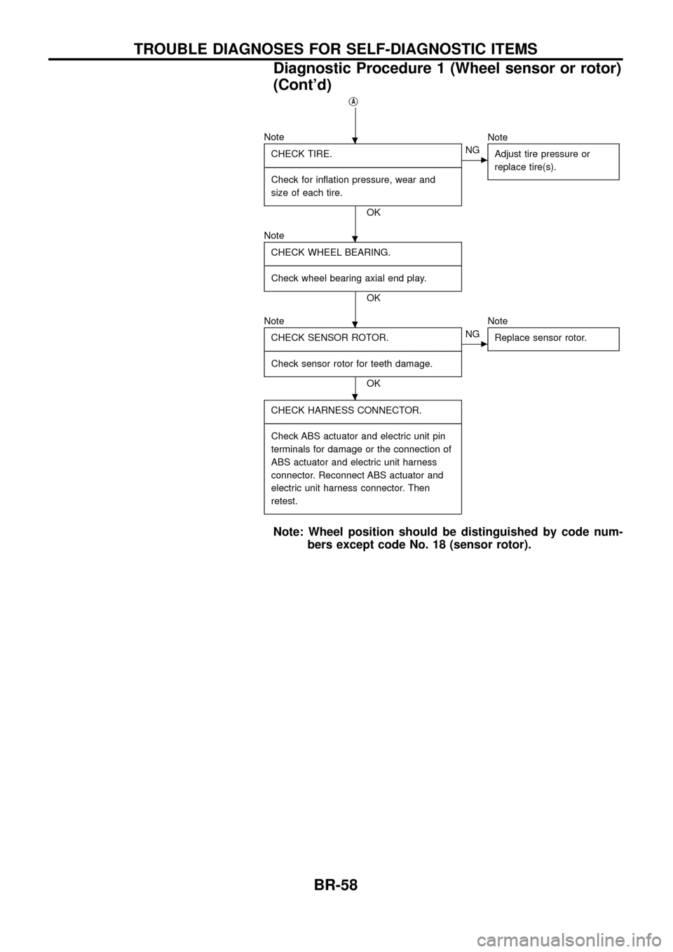
jA
NoteCHECK TIRE.
- ---------------------------------------------------------------------------------------------------------------------------------------------------------------------------------------------------------------------------------------------------------------------------------------------------------------
Check for in¯ation pressure, wear and
size of each tire.
OK
cNG Note
Adjust tire pressure or
replace tire(s).
NoteCHECK WHEEL BEARING.
- ---------------------------------------------------------------------------------------------------------------------------------------------------------------------------------------------------------------------------------------------------------------------------------------------------------------
Check wheel bearing axial end play.
OK
Note CHECK SENSOR ROTOR.
- ---------------------------------------------------------------------------------------------------------------------------------------------------------------------------------------------------------------------------------------------------------------------------------------------------------------
Check sensor rotor for teeth damage.
OK
cNG Note
Replace sensor rotor.
CHECK HARNESS CONNECTOR.
- ---------------------------------------------------------------------------------------------------------------------------------------------------------------------------------------------------------------------------------------------------------------------------------------------------------------
Check ABS actuator and electric unit pin
terminals for damage or the connection of
ABS actuator and electric unit harness
connector. Reconnect ABS actuator and
electric unit harness connector. Then
retest.
Note: Wheel position should be distinguished by code num- bers except code No. 18 (sensor rotor).
.
.
.
.
TROUBLE DIAGNOSES FOR SELF-DIAGNOSTIC ITEMS
Diagnostic Procedure 1 (Wheel sensor or rotor)
(Cont'd)
BR-58
Page 66 of 75
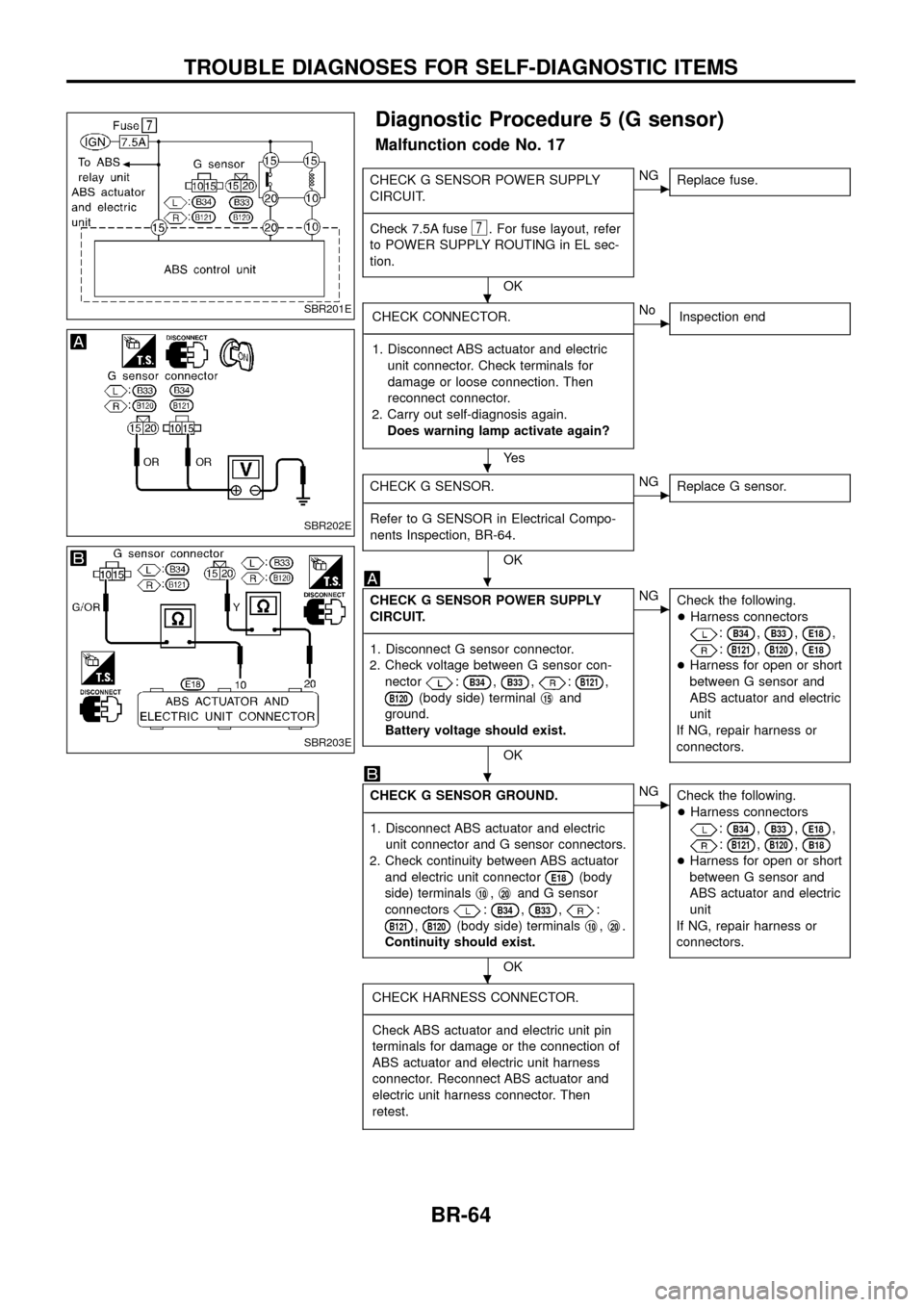
Diagnostic Procedure 5 (G sensor)
Malfunction code No. 17
CHECK G SENSOR POWER SUPPLY
CIRCUIT.
- ---------------------------------------------------------------------------------------------------------------------------------------------------------------------------------------------------------------------------------------------------------------------------------------------------------------
Check 7.5A fuse
7. For fuse layout, refer
to POWER SUPPLY ROUTING in EL sec-
tion.
OK
cNG Replace fuse.
CHECK CONNECTOR.
- ---------------------------------------------------------------------------------------------------------------------------------------------------------------------------------------------------------------------------------------------------------------------------------------------------------------
1. Disconnect ABS actuator and electric unit connector. Check terminals for
damage or loose connection. Then
reconnect connector.
2. Carry out self-diagnosis again. Does warning lamp activate again?
Ye s
cNo Inspection end
CHECK G SENSOR.
- ---------------------------------------------------------------------------------------------------------------------------------------------------------------------------------------------------------------------------------------------------------------------------------------------------------------
Refer to G SENSOR in Electrical Compo-
nents Inspection, BR-64.
OK
cNG Replace G sensor.
CHECK G SENSOR POWER SUPPLY
CIRCUIT.
- ---------------------------------------------------------------------------------------------------------------------------------------------------------------------------------------------------------------------------------------------------------------------------------------------------------------
1. Disconnect G sensor connector.
2. Check voltage between G sensor con- nector
:B34,B33,:B121,
B120(body side) terminal j15and
ground.
Battery voltage should exist.
OK
cNG Check the following.
+Harness connectors
:B34,B33,E18,
:B121,B120,E18
+Harness for open or short
between G sensor and
ABS actuator and electric
unit
If NG, repair harness or
connectors.
CHECK G SENSOR GROUND.
- ---------------------------------------------------------------------------------------------------------------------------------------------------------------------------------------------------------------------------------------------------------------------------------------------------------------
1. Disconnect ABS actuator and electric unit connector and G sensor connectors.
2. Check continuity between ABS actuator and electric unit connector
E18(body
side) terminals j
10,j20and G sensor
connectors
:B34,B33,:
B121,B120(body side) terminals j10,j20.
Continuity should exist.
OK
cNG Check the following.
+Harness connectors
:B34,B33,E18,
:B121,B120,B18
+Harness for open or short
between G sensor and
ABS actuator and electric
unit
If NG, repair harness or
connectors.
CHECK HARNESS CONNECTOR.
- ---------------------------------------------------------------------------------------------------------------------------------------------------------------------------------------------------------------------------------------------------------------------------------------------------------------
Check ABS actuator and electric unit pin
terminals for damage or the connection of
ABS actuator and electric unit harness
connector. Reconnect ABS actuator and
electric unit harness connector. Then
retest.
SBR201E
SBR202E
SBR203E
.
.
.
.
.
TROUBLE DIAGNOSES FOR SELF-DIAGNOSTIC ITEMS
BR-64
Page 67 of 75
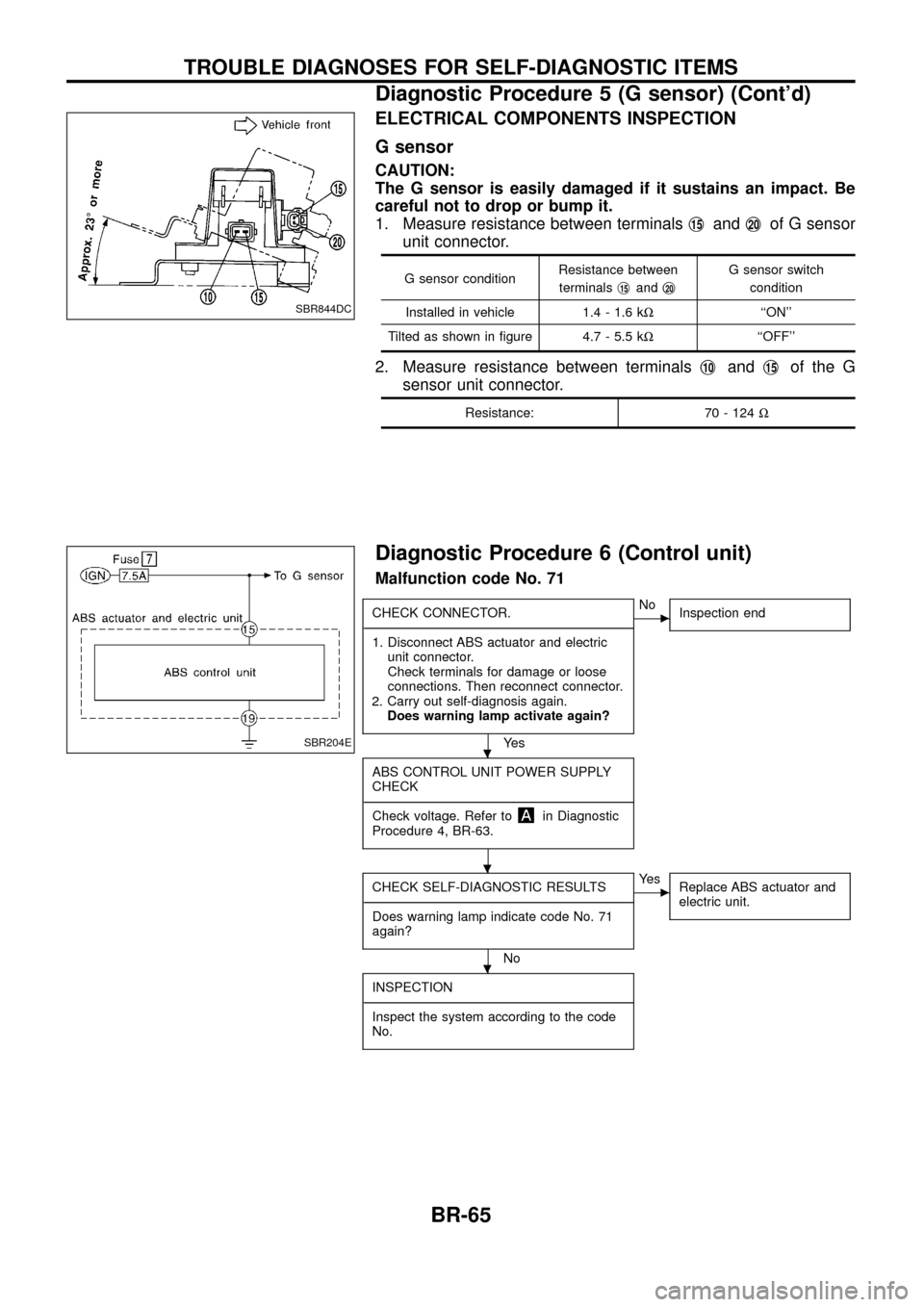
ELECTRICAL COMPONENTS INSPECTION
G sensor
CAUTION:
The G sensor is easily damaged if it sustains an impact. Be
careful not to drop or bump it.
1. Measure resistance between terminalsj
15andj20of G sensor
unit connector.
G sensor condition Resistance between
terminals j15andj20
G sensor switch
condition
Installed in vehicle 1.4 - 1.6 k W``ON''
Tilted as shown in ®gure 4.7 - 5.5 k W``OFF''
2. Measure resistance between terminals j10andj15of the G
sensor unit connector.
Resistance: 70 - 124 W
Diagnostic Procedure 6 (Control unit)
Malfunction code No. 71
CHECK CONNECTOR.
- ---------------------------------------------------------------------------------------------------------------------------------------------------------------------------------------------------------------------------------------------------------------------------------------------------------------
1. Disconnect ABS actuator and electric unit connector.
Check terminals for damage or loose
connections. Then reconnect connector.
2. Carry out self-diagnosis again. Does warning lamp activate again?
Ye s
cNo Inspection end
ABS CONTROL UNIT POWER SUPPLY
CHECK
- ---------------------------------------------------------------------------------------------------------------------------------------------------------------------------------------------------------------------------------------------------------------------------------------------------------------
Check voltage. Refer to
in Diagnostic
Procedure 4, BR-63.
CHECK SELF-DIAGNOSTIC RESULTS
- ---------------------------------------------------------------------------------------------------------------------------------------------------------------------------------------------------------------------------------------------------------------------------------------------------------------
Does warning lamp indicate code No. 71
again?
No
cYe s Replace ABS actuator and
electric unit.
INSPECTION
- ---------------------------------------------------------------------------------------------------------------------------------------------------------------------------------------------------------------------------------------------------------------------------------------------------------------
Inspect the system according to the code
No.
SBR844DC
SBR204E.
.
.
TROUBLE DIAGNOSES FOR SELF-DIAGNOSTIC ITEMS
Diagnostic Procedure 5 (G sensor) (Cont'd)
BR-65