1998 NISSAN PATROL Page 3
[x] Cancel search: Page 3Page 4 of 75
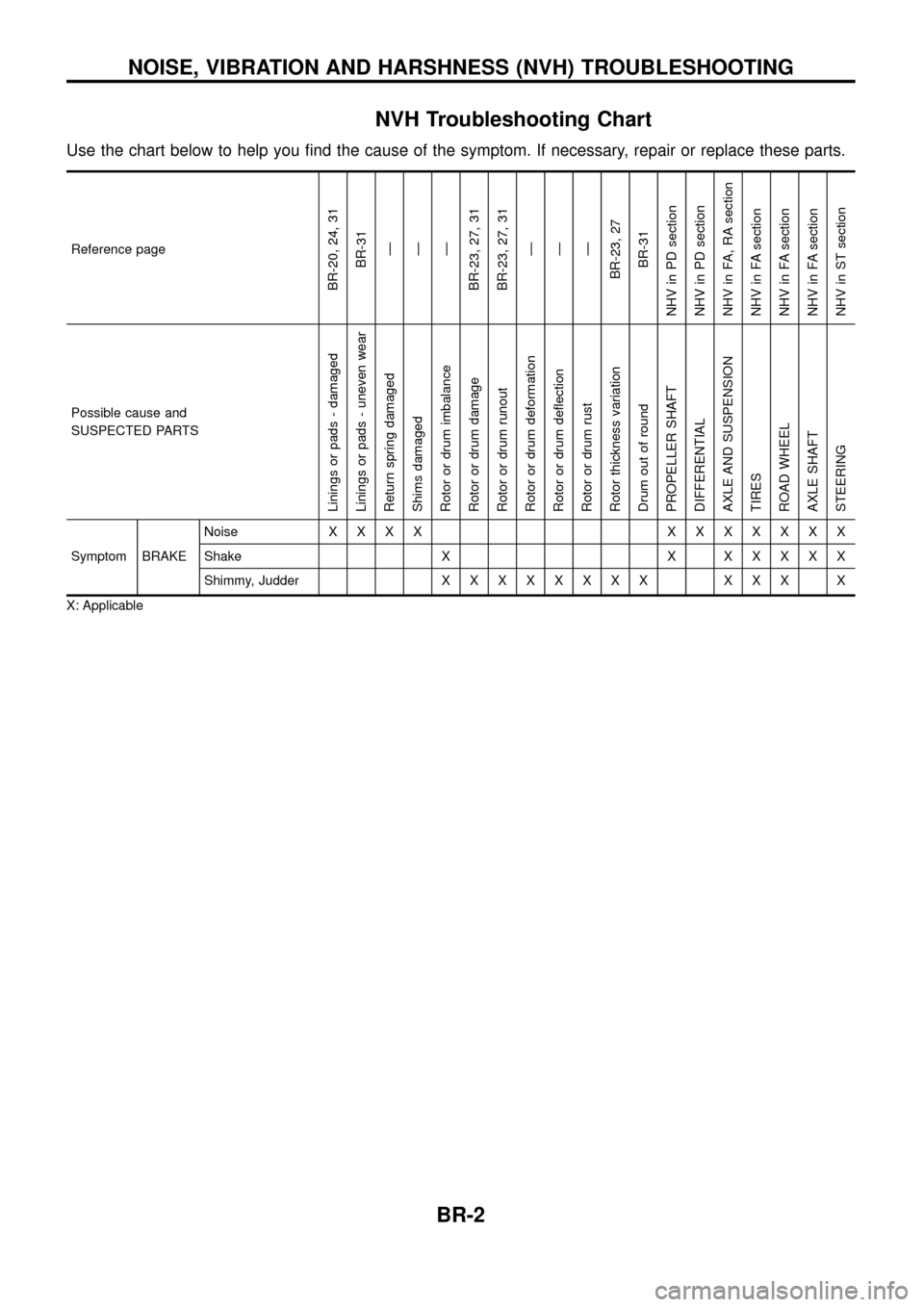
NVH Troubleshooting Chart
Use the chart below to help you ®nd the cause of the symptom. If necessary, repair or replace these parts.
Reference page
BR-20, 24, 31BR-31Ð
Ð
Ð
BR-23, 27, 31
BR-23, 27, 31 Ð
Ð
Ð
BR-23, 27 BR-31
NHV in PD section
NHV in PD section
NHV in FA, RA section
NHV in FA section
NHV in FA section
NHV in FA section
NHV in ST section
Possible cause and
SUSPECTED PARTS
Linings or pads - damaged
Linings or pads - uneven wear
Return spring damaged
Shims damaged
Rotor or drum imbalance
Rotor or drum damage
Rotor or drum runout
Rotor or drum deformation
Rotor or drum de¯ection
Rotor or drum rust
Rotor thickness variation
Drum out of round
PROPELLER SHAFT
DIFFERENTIAL
AXLE AND SUSPENSION
TIRES
ROAD WHEEL
AXLE SHAFT
STEERING
Symptom BRAKE Noise
XXXX XXXXXXX
Shake X X X X X X X
Shimmy, Judder X X XXXXXX XXX X
X: Applicable
NOISE, VIBRATION AND HARSHNESS (NVH) TROUBLESHOOTING
BR-2
Page 9 of 75
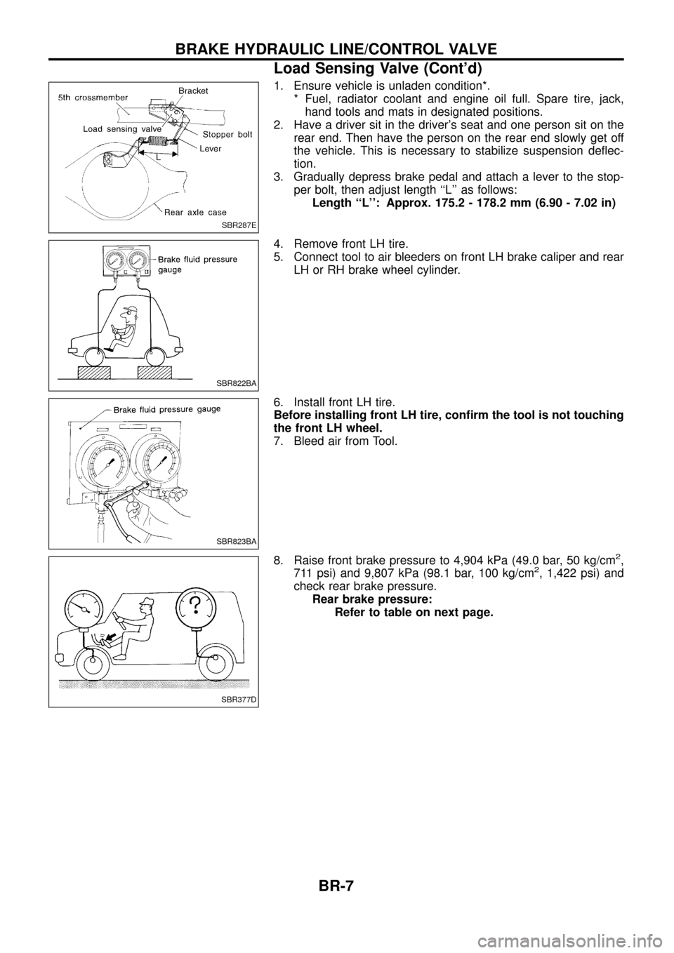
1. Ensure vehicle is unladen condition*.* Fuel, radiator coolant and engine oil full. Spare tire, jack,hand tools and mats in designated positions.
2. Have a driver sit in the driver's seat and one person sit on the rear end. Then have the person on the rear end slowly get off
the vehicle. This is necessary to stabilize suspension de¯ec-
tion.
3. Gradually depress brake pedal and attach a lever to the stop- per bolt, then adjust length ``L'' as follows:Length ``L'': Approx. 175.2 - 178.2 mm (6.90 - 7.02 in)
4. Remove front LH tire.
5. Connect tool to air bleeders on front LH brake caliper and rear LH or RH brake wheel cylinder.
6. Install front LH tire.
Before installing front LH tire, con®rm the tool is not touching
the front LH wheel.
7. Bleed air from Tool.
8. Raise front brake pressure to 4,904 kPa (49.0 bar, 50 kg/cm
2,
711 psi) and 9,807 kPa (98.1 bar, 100 kg/cm2, 1,422 psi) and
check rear brake pressure. Rear brake pressure: Refer to table on next page.
SBR287E
SBR822BA
SBR823BA
SBR377D
BRAKE HYDRAULIC LINE/CONTROL VALVE
Load Sensing Valve (Cont'd)
BR-7
Page 50 of 75
jA
Check warning lamp for deactivation after
driving vehicle over 30 km/h (19 MPH)
for at least one minute.
After making certain that warning lamp
does not come on, test the ABS in a safe
area to verify that it functions properly.
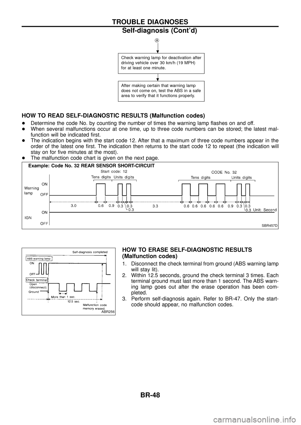
HOW TO READ SELF-DIAGNOSTIC RESULTS (Malfunction codes)
+Determine the code No. by counting the number of times the warning lamp ¯ashes on and off.
+ When several malfunctions occur at one time, up to three code numbers can be stored; the latest mal-
function will be indicated ®rst.
+ The indication begins with the start code 12. After that a maximum of three code numbers appear in the
order of the latest one ®rst. The indication then returns to the start code 12 to repeat (the indication will
stay on for ®ve minutes at the most).
+ The malfunction code chart is given on the next page.
HOW TO ERASE SELF-DIAGNOSTIC RESULTS
(Malfunction codes)
1. Disconnect the check terminal from ground (ABS warning lamp
will stay lit).
2. Within 12.5 seconds, ground the check terminal 3 times. Each terminal ground must last more than 1 second. The ABS warn-
ing lamp goes out after the erase operation has been com-
pleted.
3. Perform self-diagnosis again. Refer to BR-47. Only the start- code should appear, no malfunction codes.
SBR457D
ABR256
.
.
TROUBLE DIAGNOSES
Self-diagnosis (Cont'd)
BR-48
Page 59 of 75
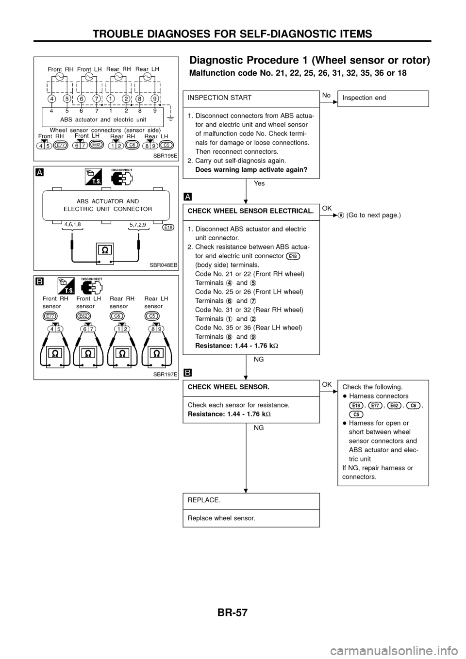
Diagnostic Procedure 1 (Wheel sensor or rotor)
Malfunction code No. 21, 22, 25, 26, 31, 32, 35, 36 or 18
INSPECTION START
- ---------------------------------------------------------------------------------------------------------------------------------------------------------------------------------------------------------------------------------------------------------------------------------------------------------------
1. Disconnect connectors from ABS actua- tor and electric unit and wheel sensor
of malfunction code No. Check termi-
nals for damage or loose connections.
Then reconnect connectors.
2. Carry out self-diagnosis again. Does warning lamp activate again?
Ye s
cNo Inspection end
CHECK WHEEL SENSOR ELECTRICAL.
- ---------------------------------------------------------------------------------------------------------------------------------------------------------------------------------------------------------------------------------------------------------------------------------------------------------------
1. Disconnect ABS actuator and electric unit connector.
2. Check resistance between ABS actua- tor and electric unit connector
E18
(body side) terminals.
Code No. 21 or 22 (Front RH wheel)
Terminals j
4andj5
Code No. 25 or 26 (Front LH wheel)
Terminals j
6andj7
Code No. 31 or 32 (Rear RH wheel)
Terminals j
1andj2
Code No. 35 or 36 (Rear LH wheel)
Terminals j
8andj9
Resistance: 1.44 - 1.76 k
W
NG
cOK
jA(Go to next page.)
CHECK WHEEL SENSOR.
- ---------------------------------------------------------------------------------------------------------------------------------------------------------------------------------------------------------------------------------------------------------------------------------------------------------------
Check each sensor for resistance.
Resistance: 1.44 - 1.76 k W
NG
cOK
Check the following.
+Harness connectors
E18,E77,E62,C6,
C5
+Harness for open or
short between wheel
sensor connectors and
ABS actuator and elec-
tric unit
If NG, repair harness or
connectors.
REPLACE.
- ---------------------------------------------------------------------------------------------------------------------------------------------------------------------------------------------------------------------------------------------------------------------------------------------------------------
Replace wheel sensor.
SBR196E
SBR048EB
SBR197E
.
.
.
TROUBLE DIAGNOSES FOR SELF-DIAGNOSTIC ITEMS
BR-57
Page 61 of 75
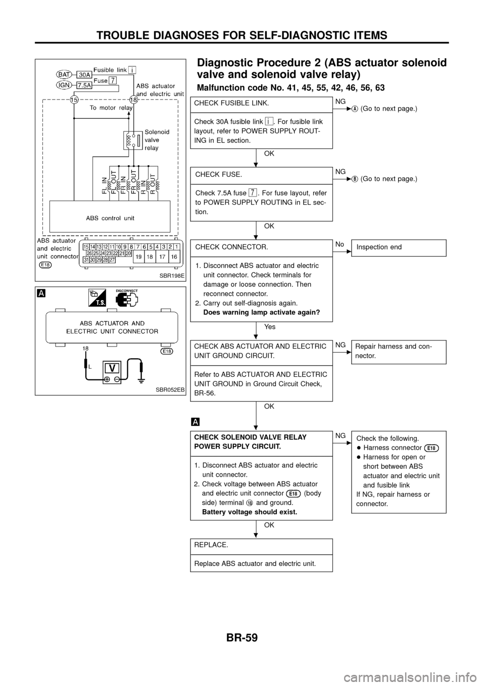
Diagnostic Procedure 2 (ABS actuator solenoid
valve and solenoid valve relay)
Malfunction code No. 41, 45, 55, 42, 46, 56, 63
CHECK FUSIBLE LINK.
- ---------------------------------------------------------------------------------------------------------------------------------------------------------------------------------------------------------------------------------------------------------------------------------------------------------------
Check 30A fusible link
i. For fusible link
layout, refer to POWER SUPPLY ROUT-
ING in EL section.
OK
cNG jA(Go to next page.)
CHECK FUSE.
- ---------------------------------------------------------------------------------------------------------------------------------------------------------------------------------------------------------------------------------------------------------------------------------------------------------------
Check 7.5A fuse
7. For fuse layout, refer
to POWER SUPPLY ROUTING in EL sec-
tion.
OK
cNG jB(Go to next page.)
CHECK CONNECTOR.
- ---------------------------------------------------------------------------------------------------------------------------------------------------------------------------------------------------------------------------------------------------------------------------------------------------------------
1. Disconnect ABS actuator and electric unit connector. Check terminals for
damage or loose connection. Then
reconnect connector.
2. Carry out self-diagnosis again. Does warning lamp activate again?
Ye s
cNo Inspection end
CHECK ABS ACTUATOR AND ELECTRIC
UNIT GROUND CIRCUIT.
- ---------------------------------------------------------------------------------------------------------------------------------------------------------------------------------------------------------------------------------------------------------------------------------------------------------------
Refer to ABS ACTUATOR AND ELECTRIC
UNIT GROUND in Ground Circuit Check,
BR-56.
OK
cNG Repair harness and con-
nector.
CHECK SOLENOID VALVE RELAY
POWER SUPPLY CIRCUIT.
- ---------------------------------------------------------------------------------------------------------------------------------------------------------------------------------------------------------------------------------------------------------------------------------------------------------------
1. Disconnect ABS actuator and electric unit connector.
2. Check voltage between ABS actuator and electric unit connector
E18(body
side) terminal j
18and ground.
Battery voltage should exist.
OK
cNG Check the following.
+Harness connector
E18
+Harness for open or
short between ABS
actuator and electric unit
and fusible link
If NG, repair harness or
connector.
REPLACE.
- ---------------------------------------------------------------------------------------------------------------------------------------------------------------------------------------------------------------------------------------------------------------------------------------------------------------
Replace ABS actuator and electric unit.
SBR198E
SBR052EB
.
.
.
.
.
TROUBLE DIAGNOSES FOR SELF-DIAGNOSTIC ITEMS
BR-59
Page 63 of 75
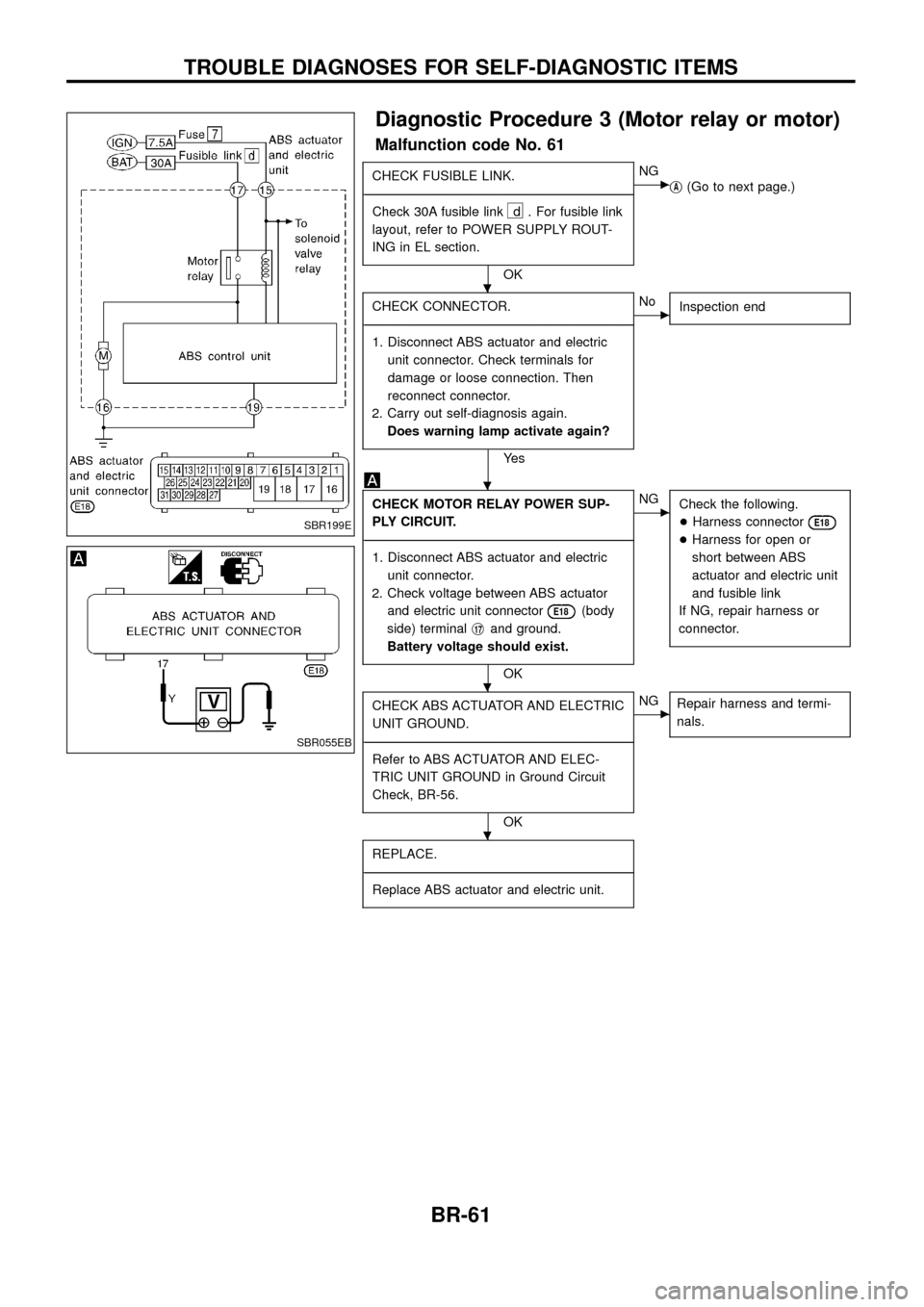
Diagnostic Procedure 3 (Motor relay or motor)
Malfunction code No. 61
CHECK FUSIBLE LINK.
- ---------------------------------------------------------------------------------------------------------------------------------------------------------------------------------------------------------------------------------------------------------------------------------------------------------------
Check 30A fusible link
d . For fusible link
layout, refer to POWER SUPPLY ROUT-
ING in EL section.
OK
cNG jA(Go to next page.)
CHECK CONNECTOR.
- ---------------------------------------------------------------------------------------------------------------------------------------------------------------------------------------------------------------------------------------------------------------------------------------------------------------
1. Disconnect ABS actuator and electric unit connector. Check terminals for
damage or loose connection. Then
reconnect connector.
2. Carry out self-diagnosis again. Does warning lamp activate again?
Ye s
cNo Inspection end
CHECK MOTOR RELAY POWER SUP-
PLY CIRCUIT.
- ---------------------------------------------------------------------------------------------------------------------------------------------------------------------------------------------------------------------------------------------------------------------------------------------------------------
1. Disconnect ABS actuator and electric unit connector.
2. Check voltage between ABS actuator and electric unit connector
E18(body
side) terminal j
17and ground.
Battery voltage should exist.
OK
cNG Check the following.
+Harness connector
E18
+Harness for open or
short between ABS
actuator and electric unit
and fusible link
If NG, repair harness or
connector.
CHECK ABS ACTUATOR AND ELECTRIC
UNIT GROUND.
- ---------------------------------------------------------------------------------------------------------------------------------------------------------------------------------------------------------------------------------------------------------------------------------------------------------------
Refer to ABS ACTUATOR AND ELEC-
TRIC UNIT GROUND in Ground Circuit
Check, BR-56.
OK
cNG Repair harness and termi-
nals.
REPLACE.
- ---------------------------------------------------------------------------------------------------------------------------------------------------------------------------------------------------------------------------------------------------------------------------------------------------------------
Replace ABS actuator and electric unit.
SBR199E
SBR055EB
.
.
.
.
TROUBLE DIAGNOSES FOR SELF-DIAGNOSTIC ITEMS
BR-61
Page 71 of 75
Note: ABS may operate and cause vibration under any of thefollowing conditions.
+ Applying brake gradually when shifting or operating
clutch.
+ Low friction (slippery) road.
+ High speed cornering.
+ Driving over bumps and pot holes.
+ Engine speed is over 5,000 rpm with vehicle stopped.
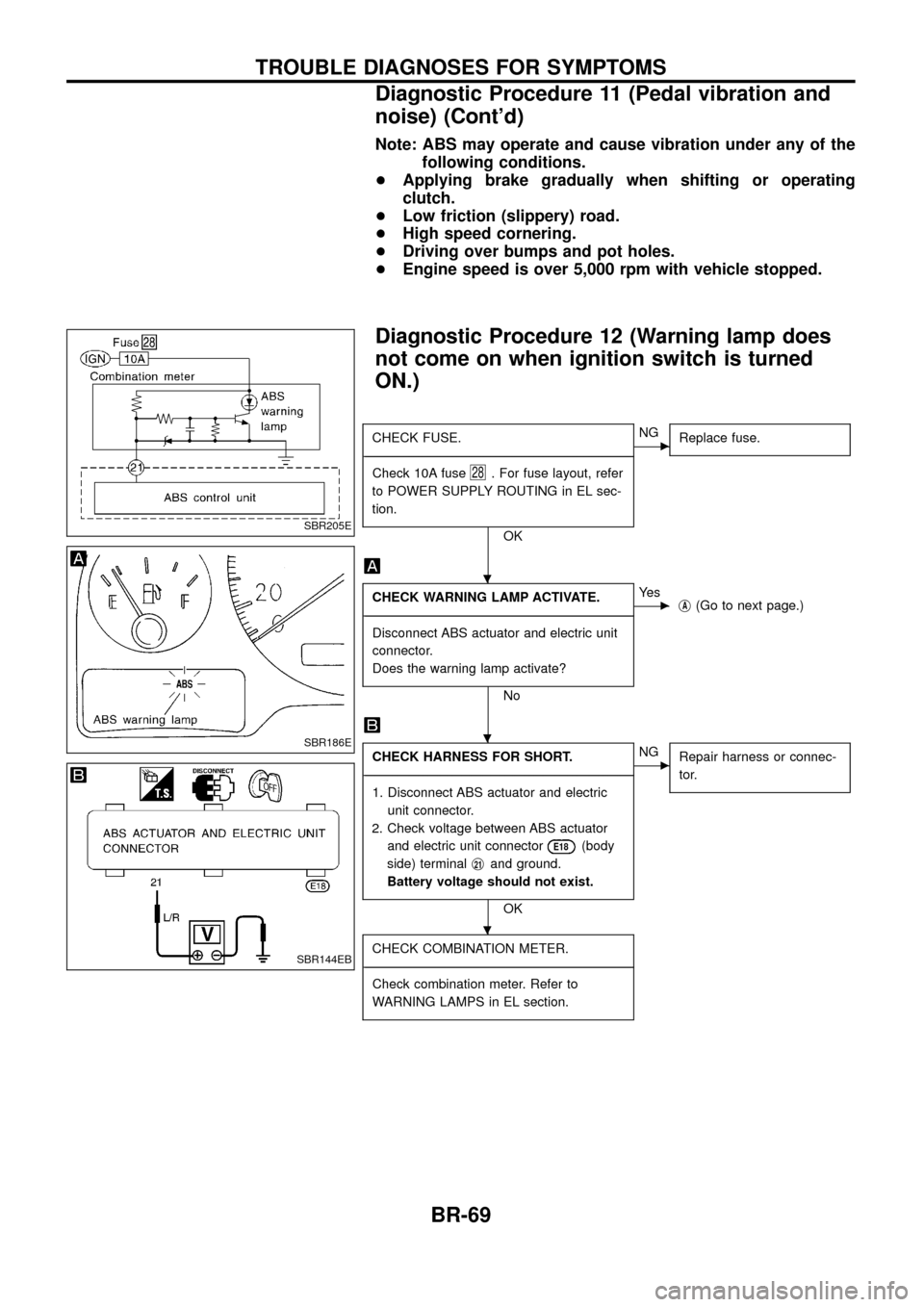
Diagnostic Procedure 12 (Warning lamp does
not come on when ignition switch is turned
ON.)
CHECK FUSE.
- ---------------------------------------------------------------------------------------------------------------------------------------------------------------------------------------------------------------------------------------------------------------------------------------------------------------
Check 10A fuse
28. For fuse layout, refer
to POWER SUPPLY ROUTING in EL sec-
tion.
OK
cNG Replace fuse.
CHECK WARNING LAMP ACTIVATE.
- ---------------------------------------------------------------------------------------------------------------------------------------------------------------------------------------------------------------------------------------------------------------------------------------------------------------
Disconnect ABS actuator and electric unit
connector.
Does the warning lamp activate?
No
cYe s jA(Go to next page.)
CHECK HARNESS FOR SHORT.
- ---------------------------------------------------------------------------------------------------------------------------------------------------------------------------------------------------------------------------------------------------------------------------------------------------------------
1. Disconnect ABS actuator and electric unit connector.
2. Check voltage between ABS actuator and electric unit connector
E18(body
side) terminal j
21and ground.
Battery voltage should not exist.
OK
cNG Repair harness or connec-
tor.
CHECK COMBINATION METER.
- ---------------------------------------------------------------------------------------------------------------------------------------------------------------------------------------------------------------------------------------------------------------------------------------------------------------
Check combination meter. Refer to
WARNING LAMPS in EL section.
SBR205E
SBR186E
SBR144EB
.
.
.
TROUBLE DIAGNOSES FOR SYMPTOMS
Diagnostic Procedure 11 (Pedal vibration and
noise) (Cont'd)
BR-69