Page 41 of 75

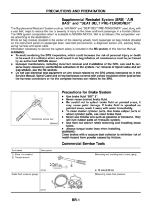
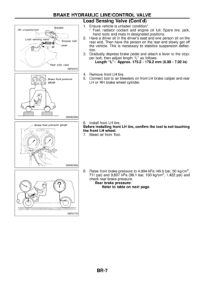
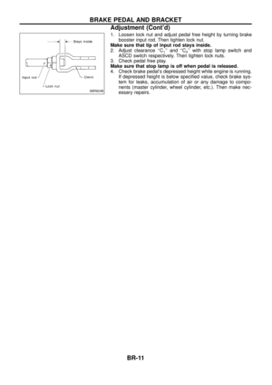
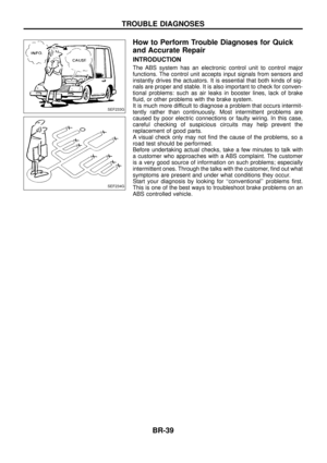
How to Perform Trouble Diagnoses for Quick
and Accurate Repair
INTRODUCTION
The ABS system has an electronic control unit to control major
functions. The control unit accepts input signals from sensors and
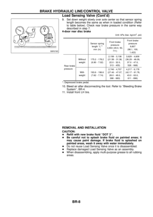
instantly drives the actuators. It is essential that both kinds of sig-
nals are proper and stable. It is also important to check for conven-
tional problems: such as air leaks in booster lines, lack of brake
¯uid, or other problems with the brake system.
It is much more difficult to diagnose a problem that occurs intermit-
tently rather than continuously. Most intermittent problems are
caused by poor electric connections or faulty wiring. In this case,
careful checking of suspicious circuits may help prevent the
replacement of good parts.
A visual check only may not ®nd the cause of the problems, so a
road test should be performed.
Before undertaking actual checks, take a few minutes to talk with
a customer who approaches with a ABS complaint. The customer
is a very good source of information on such problems; especially
intermittent ones. Through the talks with the customer, ®nd out what
symptoms are present and under what conditions they occur.
Start your diagnosis by looking for ``conventional'' problems ®rst.
This is one of the best ways to troubleshoot brake problems on an
ABS controlled vehicle.
SEF233G
SEF234G
TROUBLE DIAGNOSES
BR-39
Page 42 of 75

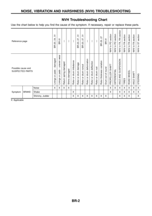
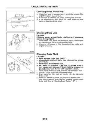
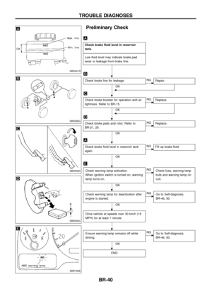
Preliminary Check
Check brake ¯uid level in reservoir
tank.
- ---------------------------------------------------------------------------------------------------------------------------------------------------------------------------------------------------------------------------------------------------------------------------------------------------------------
Low ¯uid level may indicate brake pad
wear or leakage from brake line.
Check brake line for leakage.
OKcNG Repair.
b
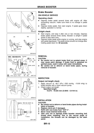
Check brake booster for operation and air
tightness. Refer to BR-15.
OK
cNGReplace.
b
Check brake pads and rotor. Refer to
BR-21, 25.
OK
cNGReplace.
Check brake ¯uid level in reservoir tank
again.
OK
cNGFill up brake ¯uid.
Check warning lamp activation.
When ignition switch is turned on, warning
lamp turns on.
OK
cNG
Check fuse, warning lamp
bulb and warning lamp cir-
cuit.
Check warning lamp for deactivation after
engine is started.
OK
cNGGo to Self-diagnosis,
BR-46, 50.
Drive vehicle at speeds over 30 km/h (19
MPH) for at least 1 minute.
Ensure warning lamp remains off while
driving.
OK
cNGGo to Self-diagnosis,
BR-46, 50.
END
SBR451D
SBR389C
SBR058C
SBR059C
SBR186E
.
.
.
.
.
.
.
.
.
TROUBLE DIAGNOSES
BR-40
Page 43 of 75
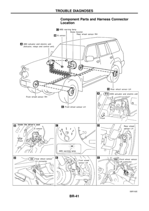
Component Parts and Harness Connector
Location
SBR192E
TROUBLE DIAGNOSES
BR-41
Page 44 of 75
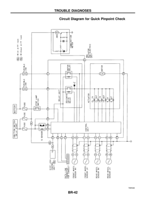
Circuit Diagram for Quick Pinpoint Check
TBR098
TROUBLE DIAGNOSES
BR-42
Page 45 of 75
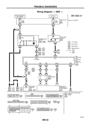
Wiring Diagram Ð ABS Ð
TBR099
TROUBLE DIAGNOSES
BR-43
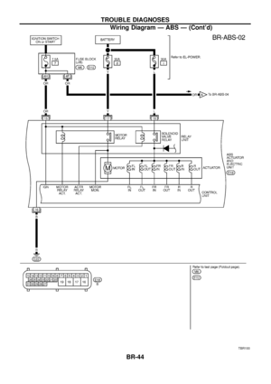
Page 46 of 75
TBR100
TROUBLE DIAGNOSES
Wiring Diagram Ð ABS Ð (Cont'd)BR-44
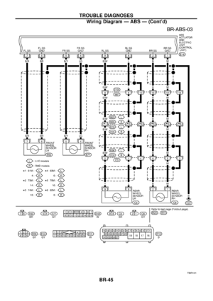
Page 47 of 75
TBR101
TROUBLE DIAGNOSES
Wiring Diagram Ð ABS Ð (Cont'd)BR-45
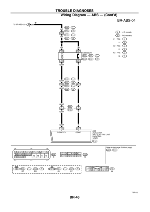
Page 48 of 75
TBR102
TROUBLE DIAGNOSES
Wiring Diagram Ð ABS Ð (Cont'd)BR-46


BR-44")
BR-45")
BR-46")