1998 JAGUAR X308 oxygen sensors
[x] Cancel search: oxygen sensorsPage 529 of 2490
Thi
s sensor uses a piezo-electric sensing element to detect kn
ock which may occur under acceleration at critical conditions.
Should detonation be present the ECM will retard ignition timing of individual cylinders.
Exhaust G
as Recirculation
The EGR
valve (where fitted) reduces NOx
emissions by recirculating a portion of the exhaust gases back into the inlet
manifold.
Heated Oxyg
en Sensors
The h
eated oxygen sensors, one per bank, are situated upstream of the catalysts. Integral
to the sensors are heaters
(under ECM control) which allow the sensor s to reach their operating temperature as soon as possible after engine start. A
comparison between the level of oxygen in the exhaust gas to that in the atmosphere produces an output signal. This signal
is used by the engine closed loop fuel strategy to make fuelling corrections and so control overall emission levels.
Oxygen Sensors
Thes
e sensors, one per bank, are situated downstream of the
catalyst. The comparison of upstream and downstream signals
allows determination of cata lyst conversion efficiency.
Knock Sensor
Page 1149 of 2490

The E
VAP canister purge valve controls th
e flow rate of fuel vapour drawn into the engine during the canister purge
operation. The valve is opened by a vacu um feed from the induction elbow : the vacu um feed is controlled by the integral
valve solenoid and is applied when the so lenoid is energised. The solenoid is pulsed on (energised) and off by a fixed
frequency (100Hz) variable pulse width control signal (pulse width modulation). By varying the pulse on to off time, the
ECM controls the duty cycle of the valve (time that the valve is open to time closed) and thus the vapour flow rate to the
engine.
With no ECM signal applied to the va lve solenoid, the valve remains closed.
Can
ister Purge Operation
The
following pre-conditions are ne
cessary for purging to commence :
aft
er battery disconnection/reconnection, engine
management adaptations must be re-instated.
engine has run for
at least 8 seconds.
engi
ne coolant temperature is not less than 70 °C.
engine
not running in the fuel
cut off condition (eg overrun).
t
he adaptive fuel correction
function has not registered a rich or lean failure
t
he evaporative emission leak test has not failed
no faults have been diagnosted in th
e rel
evant sensor and valve circuits -
Air Flow Meter (AFM), Engine Coolant
Temperature sensor, Evaporativ e Canister Purge valve and Canister Close Valve (CCV).
If these conditions have been satisfied, purging is started. If any failures are registered, purging is inhibited.
The canister(s) is purged during each driv e cycle at various rates in accordance with the prevailing engine conditions. The
engine management software st ores a map of engine speed (RPM) against engine load (grams of air inducted / rev). For
any given engine speed and load, a vapour purge rate is assigned (purge rate increases with engine speed and load).
The preset purge rates are base d on the assumption of a vapour concentratio n of 100%. The actual amount of vapour is
measured by the closed loop fueling system : the input of evaporative fuel into the engine causes the outputs from the
upstream oxygen sensors to change, the am ount of change providing a measure of the vapour concentration. This feedback
causes the original purge rate to be adju sted and also reduces the amount of fuel input via the injectors to maintain the
correct air to fuel ratio.
Engine speed/load mapping and the corresp onding purge rates are different for single canister, running loss and ORVR
evaporative systems.
Page 1177 of 2490
Th
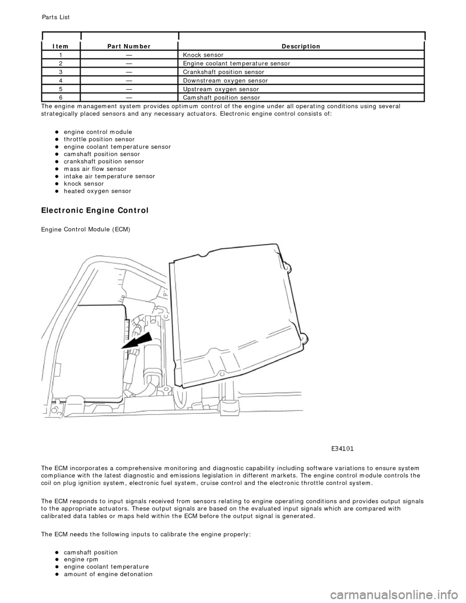
e engine management system provides optimum control of
the engine under all operating conditions using several
strategically placed sensors and any necessary actuators. Electronic engine control consists of:
engine
control module
throttle posi
tion sensor
engi
ne coolant temperature sensor
cam
shaft position sensor
c
rankshaft position sensor
mass air
flow sensor
intake air temper
ature sensor
kn
ock sensor
heat
ed oxygen sensor
Electronic Engine Control
Engine
Control Module (ECM)
The ECM incorporates a comprehensive monitoring and diagnostic capability including software variations to ensure system
compliance with the latest diagnostic and emissions legislation in different markets. The engine control module controls the
coil on plug ignition system, electronic fuel system, cr uise control and the electronic throttle control system.
The ECM responds to input signals received from sensors relating to engine operatin g conditions and provides output signals
to the appropriate actuators. These outp ut signals are based on the evaluated input signals which are compared with
calibrated data tables or maps held within th e ECM before the output signal is generated.
The ECM needs the following inputs to calibrate the engine properly:
cam
shaft position
It
em
Par
t Number
De
scription
1—Knock
sensor
2—Engine
coolant temperature sensor
3—Cranksh
aft position sensor
4—D
ownstream oxygen sensor
5—Upstream oxygen sensor
6—Camshaft position
sensor
P
arts List
engi
ne rpm
engi
ne coolant temperature
amount
of engine detonation
Page 1179 of 2490
generates a signal when th
e dr
ive plate passes the sensor
sen
ds the ECM signals indicating crankshaft position and engine speed
is e
ssential for calculating spark timing
En
gine Coolant Temperature (ECT) Sensor
sen
ds the ECM a signal indicating the temperature of the engine coolant
is a t
emperature dependent resistor with a negative temperature coefficient (resistance changes inversely with
respect to temperature) and is constantly monitored by the ECM
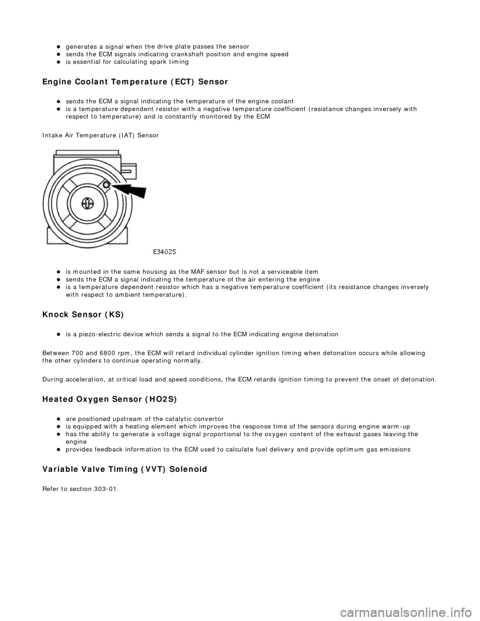
Intake Air Temperature (IAT) Sensor
is m
ounted in the same housing as the MA
F sensor but is not a serviceable item
sen
ds the ECM a signal indicating the temperature of the air entering the engine
is a t
emperature dependent resistor which has a negative
temperature coefficient (its resistance changes inversely
with respect to ambient temperature).
Knock S
ensor (KS)
is a pi
ezo-electric device which sends a signal
to the ECM indicating engine detonation
Between 700 and 6800 rpm, the ECM will retard individual cylinder ignition timing when detonation occurs while allowing
the other cylinders to continue operating normally.
During acceleration, at critical load and speed conditions, the ECM retards ignition timing to prevent the onset of detonation.
H
eated Oxygen Sensor (HO2S)
are
positioned upstream of the catalytic convertor
is equipped with
a heating element wh
ich improves the response time of the sensors during engine warm-up
h
as the ability to generate a voltage signal proportional to the oxygen content of the exhaust gases leaving the
engine
pr
ovides feedback information to the ECM used to calc
ulate fuel delivery and provide optimum gas emissions
Variable V
alve Timing (VVT) Solenoid
R
efer to section 303-01.
Page 1188 of 2490
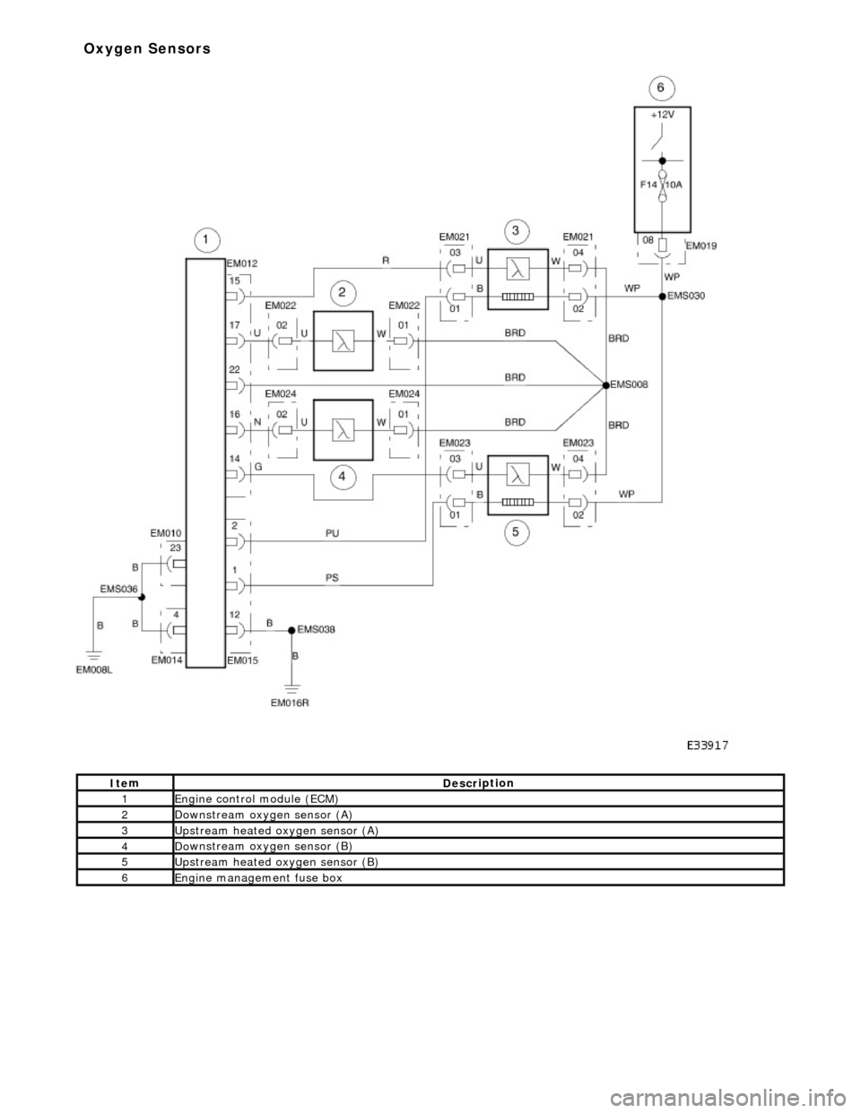
It e
m
De
scr
iption
1Engine
c
ontrol
module (ECM)
2Do
wnstream oxygen sensor (A)
3Upstream heated ox
ygen sensor
(A)
4D
o
wnstream oxygen sensor (B)
5Upstream heated ox
ygen sensor (B)
6Engine
management fuse box
Ox
yg
en Sensors
Page 1530 of 2490
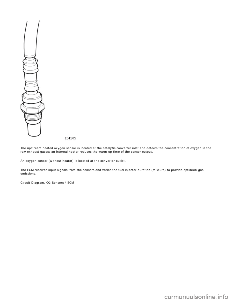
The upstream heated oxygen sensor is located at the catalytic converter inlet and detects the concentration of oxygen in the
raw exhaust gases; an internal heater reduces the warm up time of the sensor output.
An oxygen sensor (without heater) is located at the converter outlet.
The ECM receives input signals from the se nsors and varies the fuel injector duration (mixture) to provide optimum gas
emissions.
Circuit Diagram, O2 Sensors / ECM
Page 2361 of 2490
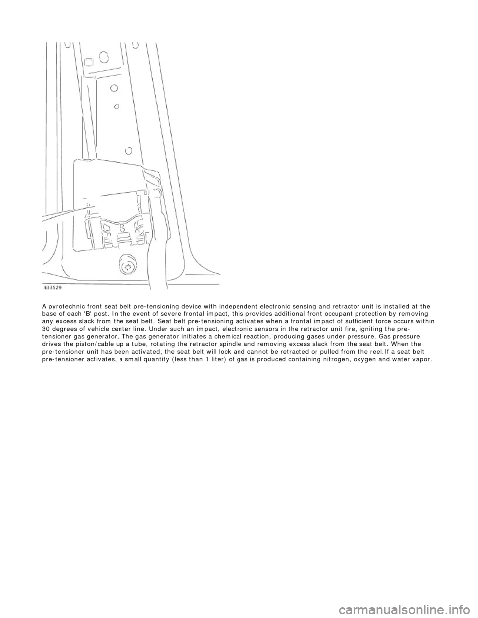
A pyrotechnic front seat belt pre-tensioning device with independent el ectronic sensing and retractor unit is installed at the
base of each 'B' post. In the event of se vere frontal impact, this provides additional front occupant protection by removing
any excess slack from the seat be lt. Seat belt pre-tensioning activates when a frontal impact of sufficient force occurs within
30 degrees of vehicle center line. Under such an impact, el ectronic sensors in the retractor unit fire, igniting the pre-
tensioner gas generator. The ga s generator initiates a chemical reaction, producing gases under pressure. Gas pressure
drives the piston/cable up a tube, rotating the retractor sp indle and removing excess slack from the seat belt. When the
pre-tensioner unit has been activated, the seat belt will lock and cannot be retracted or pulled from the reel.If a seat belt
pre-tensioner activates, a small quantity (less than 1 liter) of gas is produced containing nitrogen, oxygen and water vapor.