Page 1443 of 2490
Automatic Transmission/Transaxle - 4.0L SC V8 - AJ26 - Transmission
Internal Wiring Harness Electr ical Connector O-Ring Seals
In-vehicle Repair
Removal
1. Disconnect the batt ery ground cable.
2. Open the engine compartment and fit paint protection sheets.
3. Raise the vehicle for access.
4. WARNING: TRANSMISSION FLUID MAY CAUSE SEVERE
BURNS, ENSURE THAT ALL SAFET Y PROCEDURES ARE OBSERVED
AND THAT THE RECEPTACLE FOR WASTE HAS SUFFICIENT
CAPACITY.
Drain the transmission fluid.
Carefully remove the drain pl ug and discard the sealing
washer.
5. Remove the harness heatshield lower fixing.
Remove the screw heatshield / fluid pan clamp.
6. Remove the harness heatshield.
Pull the heatshield from under the clip.
7. Disconnect the transmission link harness connector.
1. Release the locking lever on the guide bush and disconnect the harness connector.
Page 1446 of 2490
Automatic Transmission/Transaxle - 4.0L SC V8 - AJ26 - Transmission
Support Insulator
In-vehicle Repair
Removal
Installation
1. Raise the vehicle on a ramp to a suitable height for working on
the rear mounting.
2. Remove the bolt which secure s the engine rear mounting
rubber to the transmission.
3. Position a transmission jack under the transmission casing.
Take the weight of the transmission on the jack.
4. Remove the rear mounting rubber.
1. Slacken the four bolt s which secure the rear
crossmember to the vehicle floor.
2. Remove the two bolts which secure the mounting rubber to the crossmember.
3. Remove the mounting rubber.
1. Fit the mounting rubber assembly to position and tighten the
centre bolt to 30-40 Nm .
2. Tighten the crossmember to body bolts and the mounting
rubber to crossmember bolts to 22-28 Nm.
Page 1448 of 2490
Automatic Transmission/Transaxle - 4.0L SC V8 - AJ26 - Transmission
Removal
Removal
Special Tool(s)
Engine support
303-021
Engine lifting brackets
303-536
1. Select N gear position.
2. Disconnect the battery ground lead.
3. Remove the engine covers. Re fer to Operation 12.30.06.
4. Remove the air intake tube, MAFM and air cleaner cover
assembly. Refer to Operation 19.10.30.
5. Disconnect the transmission link lead connector.
1. Release the connector fr om its mounting bracket.
2. Disconnect the multiplug.
6. Remove the EMS harness mounting bracket.
Release the bolt, bracket to cylinder head.
7. Fit engine lifting bracket 307 - 536 at the rear RH.
Page 1456 of 2490

Automatic Transmission/Transaxle - 4.0L SC V8 - AJ26 - Input Shaft Seal
Disassembly and Assembly of Subassemblies
Special Tool(s)
Oil seal replacer
307-378
1. Disconnect the battery ground lead.
2. Remove the air intake / MAFM assembly, refer to Operation
19.10.30.
3. Raise the vehicle for access.
4. Remove the front muffler, 30.10.18
5. Remove the RH and LH catalytic converters, refer to Operation
17.50.09 and 17.50.10.
6. Drain the transmission fluid, refer to Operation 44.24.02.
7. Remove the transmission unit, refer to Operation 44.20.01.
8. Remove the torque converter fro m the transmission unit, refer
to Operation 44.17.07.
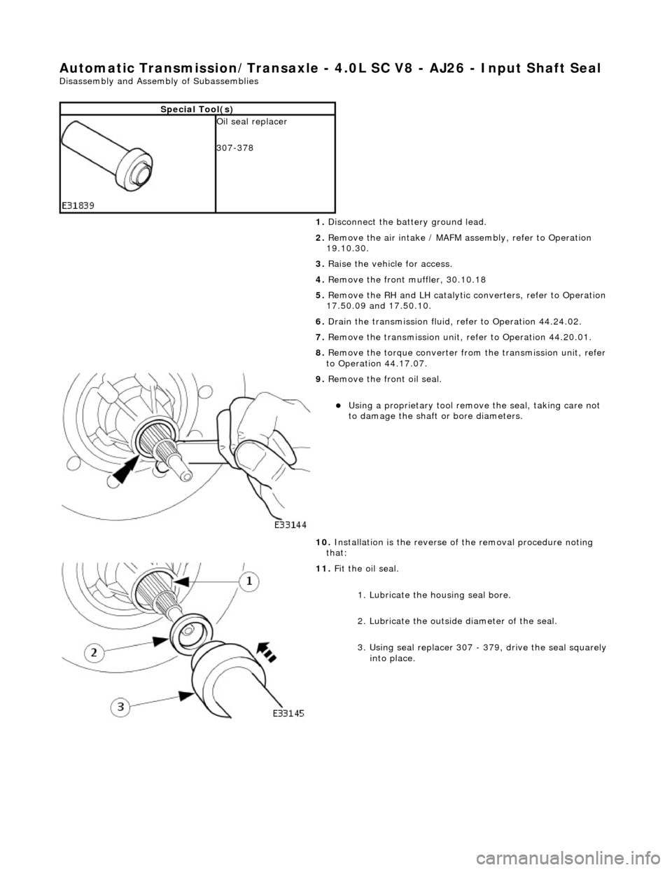
9. Remove the front oil seal.
Using a proprietary tool remove the seal, taking care not
to damage the shaft or bore diameters.
10. Installation is the reverse of the removal procedure noting
that:
11. Fit the oil seal.
1. Lubricate the housing seal bore.
2. Lubricate the outside diameter of the seal.
3. Using seal replacer 307 - 379, drive the seal squarely into place.
Page 1457 of 2490

Automatic Transmission/Transaxle - 4.0L SC V8 - AJ26 - Torque Converter
Disassembly and Assembly of Subassemblies
CAUTION: If the transmission is to be renewed, renew the to rque converter also.
Special Tool(s)
Torque converter lifting handles
307-139
1. Remove the transmission unit from the vehicle; refer to
Operation 44.20.01.
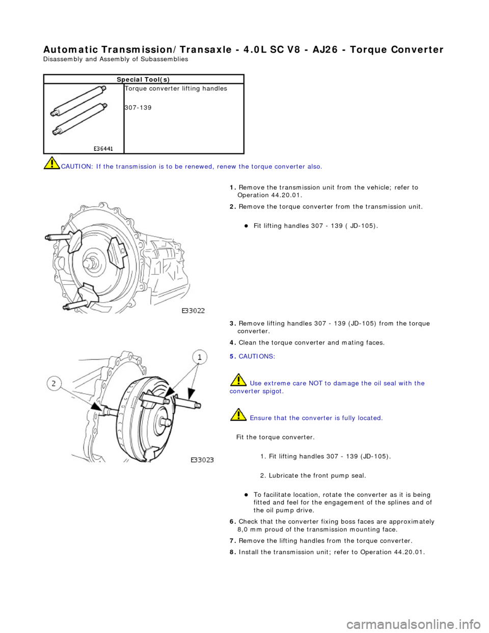
2. Remove the torque converter from the transmission unit.
Fit lifting handles 307 - 139 ( JD-105).
3. Remove lifting handles 307 - 139 (JD-105) from the torque
converter.
4. Clean the torque conver ter and mating faces.
5. CAUTIONS:
Use extreme care NOT to damage the oil seal with the
converter spigot.
Ensure that the conver ter is fully located.
Fit the torque converter.
1. Fit lifting handles 307 - 139 (JD-105).
2. Lubricate the front pump seal.
To facilitate location, rotate the converter as it is being
fitted and feel for the engage ment of the splines and of
the oil pump drive.
6. Check that the converter fixing boss faces are approximately
8,0 mm proud of the transm ission mounting face.
7. Remove the lifting handles from the torque converter.
8. Install the transmission unit; refer to Operation 44.20.01.
Page 1458 of 2490
Automatic Transmission/Transaxle - 4.0L SC V8 - AJ26 - Transmission
Installation
Installation
Special Tool(s)
Engine support
303-021
Engine lifting brackets
303-536
1. CAUTION: A new transmission requires a NEW torque
converter.
Installation is the re verse of the removal procedure, noting the
following:
2. Clean all mating faces and relevant parts.
3. Apply lubricant, MOLYCOTE or equivalent to the torque
converter spigot.
4. Fit the screw (lower) securing th e harness link lead heatshield.
Tighten to the specified torque figure.
5. Fit the dipstick lower tube.
Remove the blanking plug and fit a new O-ring seal.
Tighten the bolt to the specified torque figure.
Page 1464 of 2490
Automatic Transmission/Transaxle External Controls - 4.0L NA V8 -
AJ27/3.2L NA V8 - AJ26 - External Controls
Description and Operation
Introduction
Driver gearshift control is effected by:
The gear shift lever. The accelerator pedal position. The kickdown switch (where fitted). The performance mode pushbutton.
Driver's Selector Module ('J' Gate)
The gear selector lever:
Has seven positions: Park, Reverse, Neutral, Drive, Fourth, Third and Second. Operates the transmission selector shaft and rotary switch, in all positions (except Drive-to-fourth) by means of a
Bowden cable.
Passes driver gearshift requests to the transm ission control module via the rotary switch.
ItemPart NumberDescription
1—Gear selector lever
2—Drive-to-fourth switch connector
3—Neutral position switch connector
4—Park position switch connector
5—Gear selector illumination module
6—Gear selector interlock solenoid
7—Security system Active LED
Page 1469 of 2490
Automatic Transmission/Transaxle External Controls - 4.0L NA V8 -
AJ27/3.2L NA V8 - AJ26 - External Controls
Diagnosis and Testing
Symptom Chart
Symptom Chart
Pinpoint test A: P0706
Special Tool(s)
Digital multimeter
Generic scantool
SymptomPossible SourcesAction
DTC P0706 Transmission range sensor circuit range /
performanceSelector cable maladjusted
Rotary switch fault
D to 4 switch fault
Rotary position switch fault
Harness fault
Connector pins(s) bent, loose or
corroded
*
*
*
*
*
*GO to Pinpoint Test A
*
PINPOINT TEST A : P0706
TEST CONDITIONSDETAILS/RESULTS/ACTIONS
A1: RETRIEVE DTCS
• NOTE: Battery and or ECM disconnection prior to scanning wi
ll erase all data, ensure that the correct DTC is present.
Connect the scan tool 1
Have the DTC(s) and freeze frame data been recorded?
Yes GO to A2
A2: STATUS / RELATIONSHIP CHECK