Page 1509 of 2490

Automatic Transmission/Transax
le External Controls
- 4.0L SC V8 - AJ26 -
Kickdown Switch Adjustment
Gen
eral Procedures
1. Ensure that the throttle cable is correctly adjusted; refer to
Operation 19.20.06.
2. Refer to the PDU User Guide for relevant software - 1040.
3. With PDU connected, running and the message 'EXISTING
COMPONENTS TO BE TESTED YES / NO' displayed:
Select YES.
Select ENTER.
Fol
low the messages given on the screen.
4. Press ENTER on the PDU screen.
5. F
ollowing the PDU instructions:
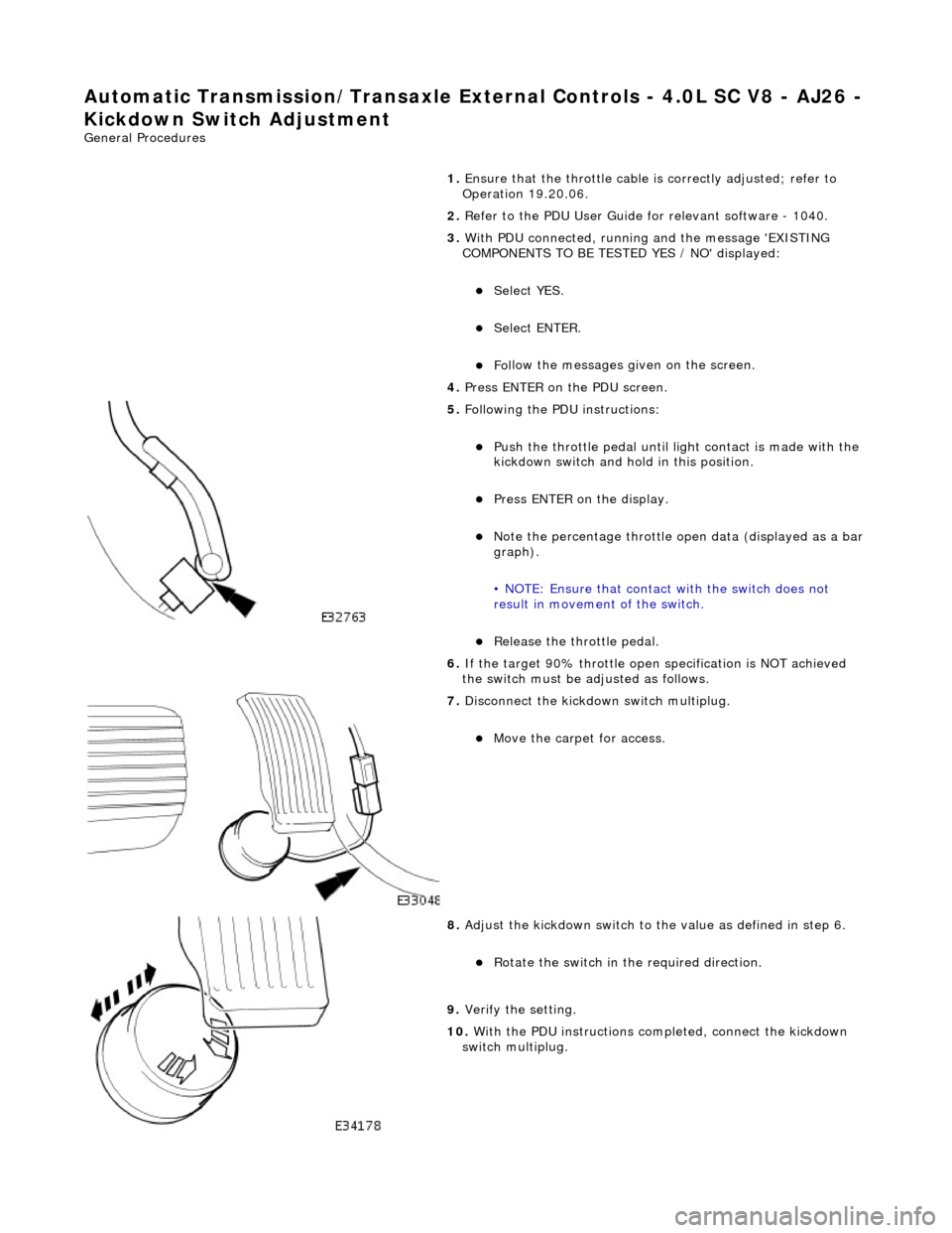
Push the throttl
e pedal until li
ght contact is made with the
kickdown switch and hold in this position.
Pres
s ENTER on the display.
No
te the percentage throttle op
en data (displayed as a bar
graph).
• NOTE: Ensure that contact with the switch does not
result in movement of the switch.
R
elease the throttle pedal.
6. If the target 90% throttle open specification is NOT achieved
the switch must be ad justed as follows.
7. Di
sconnect the kickdown switch multiplug.
Move the car
pet for access.
8. Adjust
the kickdown switch to th
e value as defined in step 6.
R
otate the switch in th
e required direction.
9.
Veri
fy the setting.
10. With the PDU instructions completed, connect the kickdown
switch multiplug.
Page 1510 of 2490

Automatic Transmission/Transaxle External Contro ls - 4.0L SC V8 - AJ26 -
Selector Lever Cable Adjustment
General Procedures
1.
Disconnect the vehicle battery ground lead.
2. Position the gear sele ctor lever to N.
3. Remove the J-gate surround, Section 501-05.
4. Remove the console finisher ve neer panel, Section 501-12.
5. Remove the center console assembly, Section 501-12.
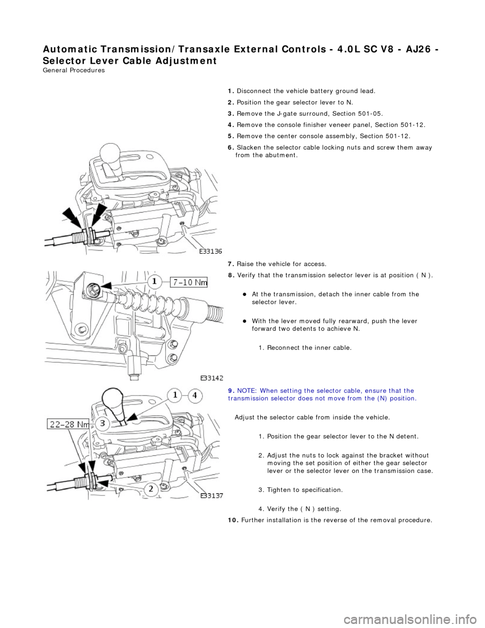
6. Slacken the selector cable lock ing nuts and screw them away
from the abutment.
7. Raise the vehicle for access.
8. Verify that the transmis sion selector lever is at position ( N ).
At the transmission, detach the inner cable from the
selector lever.
With the lever moved fully rearward, push the lever
forward two detents to achieve N.
1. Reconnect the inner cable.
9. NOTE: When setting the selector cable, ensure that the
transmission selector does no t move from the (N) position.
Adjust the selector cable from inside the vehicle. 1. Position the gear select or lever to the N detent.
2. Adjust the nuts to lock against the bracket without moving the set position of either the gear selector
lever or the select or lever on the transmission case.
3. Tighten to specification.
4. Verify the ( N ) setting.
10. Further installation is the reve rse of the removal procedure.
Page 1511 of 2490
Automatic Transmission/Transaxle External Contro ls - 4.0L SC V8 - AJ26 -
Brake Shift Interlock Actuator
Removal and Installation
Removal
Installation
1.
Disconnect the vehicle battery ground lead.
2. Remove the J-gate surround, Section 501-05.
3. Remove the console finisher ve neer panel, Section 501-12.
4. Remove the interlock so lenoid lever cover.
5. Remove the gearshift interlock solenoid.
1. Remove the (2) solenoid nuts.
2. Detach the solenoid from the latch pin.
3. Disconnect the solenoid multiplug.
1. Installation is th e reverse of the re moval procedure.
2. Refer to the illustration.
Page 1512 of 2490
Automatic Transmission/Transaxle External Contro ls - 4.0L SC V8 - AJ26 -
Kickdown Switch
Removal and Installation
Removal
Installation
1. Disconnect the kickdown switch multiplug.
Move the carpet for access.
2. Remove the kickdown switch.
Rotate counter-clockwise.
1. Installation is th e reverse of the re moval procedure.
2. The kickdown switch MUST be adjusted in accordance with
(44.15.38).
Page 1513 of 2490
Automatic Transmission/Transaxle External Contro ls - 4.0L SC V8 - AJ26 -
Selector Lever Cable and Bracket
Removal and Installation
Removal
1. Disconnect the vehicle battery ground lead.
2. Position the selector to N.
3. Remove the J-gate surround, Section 501-05.
4. Remove the console finisher ve neer panel, Section 501-12.
5. Remove the center console assembly, Section 501-12.
6. Raise the vehicle for access.
7. Detach the gear selector cable from the transmission unit.
1. Remove the nut which secures the selector cable ball pin to the selector lever.
2. Lower the transmissi on lift for access.
3. Remove the bolts which secure the selector cable to the transmission casing.
8. Reposition the selector cable.
9. Remove the LH front seat, Section 501-10.
10. Reposition the LH floo r carpet for access.
11. Remove the selector cable to tunnel clip tie strap.
12. Detach the selector cable from the gear shift assembly.
1. Remove the inner cable to shift lever nut.
Page 1516 of 2490
Automatic Transmission/Transaxle External Contro ls - 4.0L SC V8 - AJ26 -
Selector Lever Gate Finish Panel
Removal and Installation
Removal
Installation
1.
Apply protective tape to veneer along each side of 'J' gate
finisher.
2. Using a screwdriver in the slot in front of the finisher,
carefully lift the finisher an d ease it from the 'J' gate
surround.
1. Position finisher over gear selector.
2. Firmly seat finisher on veneer panel.
3. Remove protective tape from ve neer panel and using a suitable
cleaner, remove any residual adhesive.
Page 1517 of 2490
Automatic Transmission/Transaxle External Contro ls - 4.0L SC V8 - AJ26 -
Selector Lever Indicator Disc
Removal and Installation
Removal
Installation
1.
Disconnect the vehicle battery ground lead.
2. Remove the selector indicator module; Operation 44.15.14.
3. Remove the selector indicator module disc.
Remove the disc retaining screw.
1. Installation is th e reverse of the re moval procedure.
Page 1518 of 2490

Automatic Transmission/Transaxle External Contro ls - 4.0L SC V8 - AJ26 -
Transmission Control Switch (TCS)
Removal and Installation
Removal
Installation
1. Position the gear selector to 'N' to provide clearance for
removing the console.
2. Disconnect the vehicle battery ground lead.
3. Remove the J-gate surroun d, operation 76.25.24.
4. Remove the console finisher vene er panel, operation 76.47.26.
5. Remove the console assembly, operation 76.25.01.
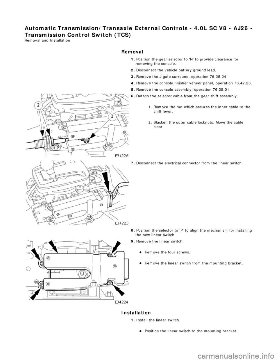
6. Detach the selector cable from the gear shift assembly.
1. Remove the nut which secures the inner cable to the shift lever.
2. Slacken the outer cable locknuts. Move the cable clear.
7. Disconnect the electrical conne ctor from the linear switch.
8. Position the selector to 'P' to align the mechanism for installing
the new linear switch.
9. Remove the linear switch.
Remove the four screws.
Remove the linear switch fro m the mounting bracket.
1. Install the linear switch.
Position the linear switch to the mounting bracket.