Page 1864 of 2490
Information and Message Center - Information and Message Center
Description and Operation
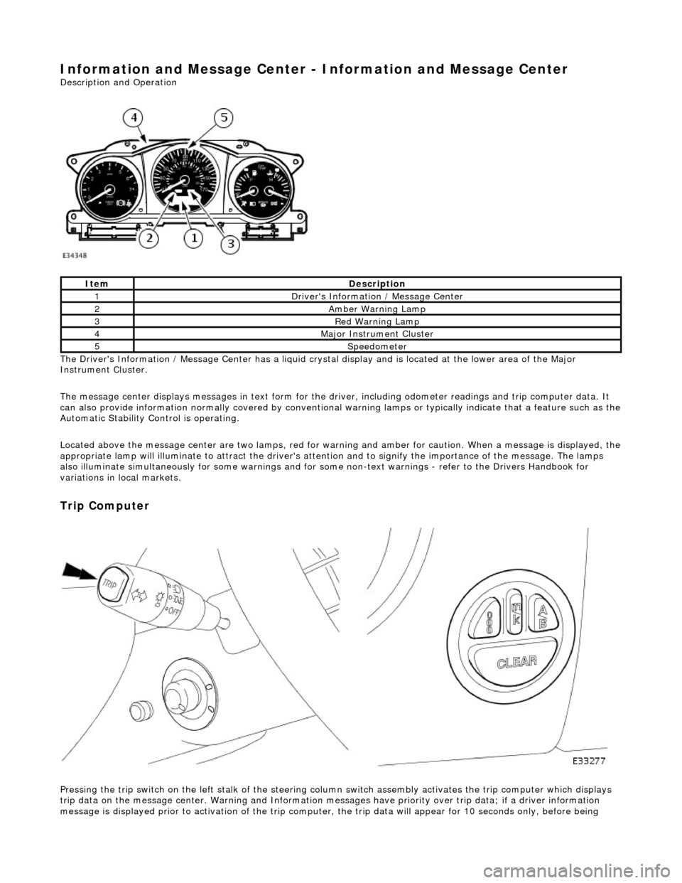
The Driver's Information / Message Center has a liquid crystal display and is located at the lower area of the Major
Instrument Cluster.
The message center displays messages in text form for the driver, including odometer readings an d trip computer data. It
can also provide information normally covered by conventional wa rning lamps or typically indicate that a feature such as the
Automatic Stability Control is operating.
Located above the message center are two lamps, red for warning and amber for caution. When a message is displayed, the
appropriate lamp will illuminate to attract the driver's attention and to signify the importance of the message. The lamps
also illuminate simultaneously for some warnings and for some non-text warnin gs - refer to the Drivers Handbook for
variations in local markets.
Trip Computer
Pressing the trip switch on the left stalk of the steering colu mn switch assembly activates the trip computer which displays
trip data on the message center. Warning and Information messages have priority ov er trip data; if a driver information
message is displayed prior to activation of the trip computer , the trip data will appear for 10 seconds only, before being
ItemDescription
1Driver's Information / Message Center
2Amber Warning Lamp
3Red Warning Lamp
4Major Instrument Cluster
5Speedometer
Page 1869 of 2490
The functi
on of the parking aid is to prov
ide an audible warning to the driver of the distance to obstacles near the rear
bumper of the vehicle when parking or travelling at a slow sp eed. The system provides an assistance to the driver when
parking in order to help avoid collision with obstacles.
The sensor range at the rear of the vehicl e should be 1.8 meters. This should extend the full width of the rear bumper and
reduce to 50 cm at the vehicle co rners. The vertical range is adequate to protec t the highest and lowest points of the rear of
the vehicle. The system will detect curbs with heights of at least 18 cm. Obstacles, such as curbs, that are low enough to
pass under the vehicle until they make contact with the tires will not be detected.
The system activates a specific speaker with a tone signifying the distance to the obstacle. The tone consists of a beep and
defined space ratio which varies depending on the calculated distance. When the distance to the obstacle is less than 20 cm
the speaker tone is continuous.
The parking aid is continuously in operation, unless towing wh en the system automatically switches off. If the reverse aid
develops a fault the tone will sound continuously for three seconds when the igni tion is switched on or the reverse gear is
selected.
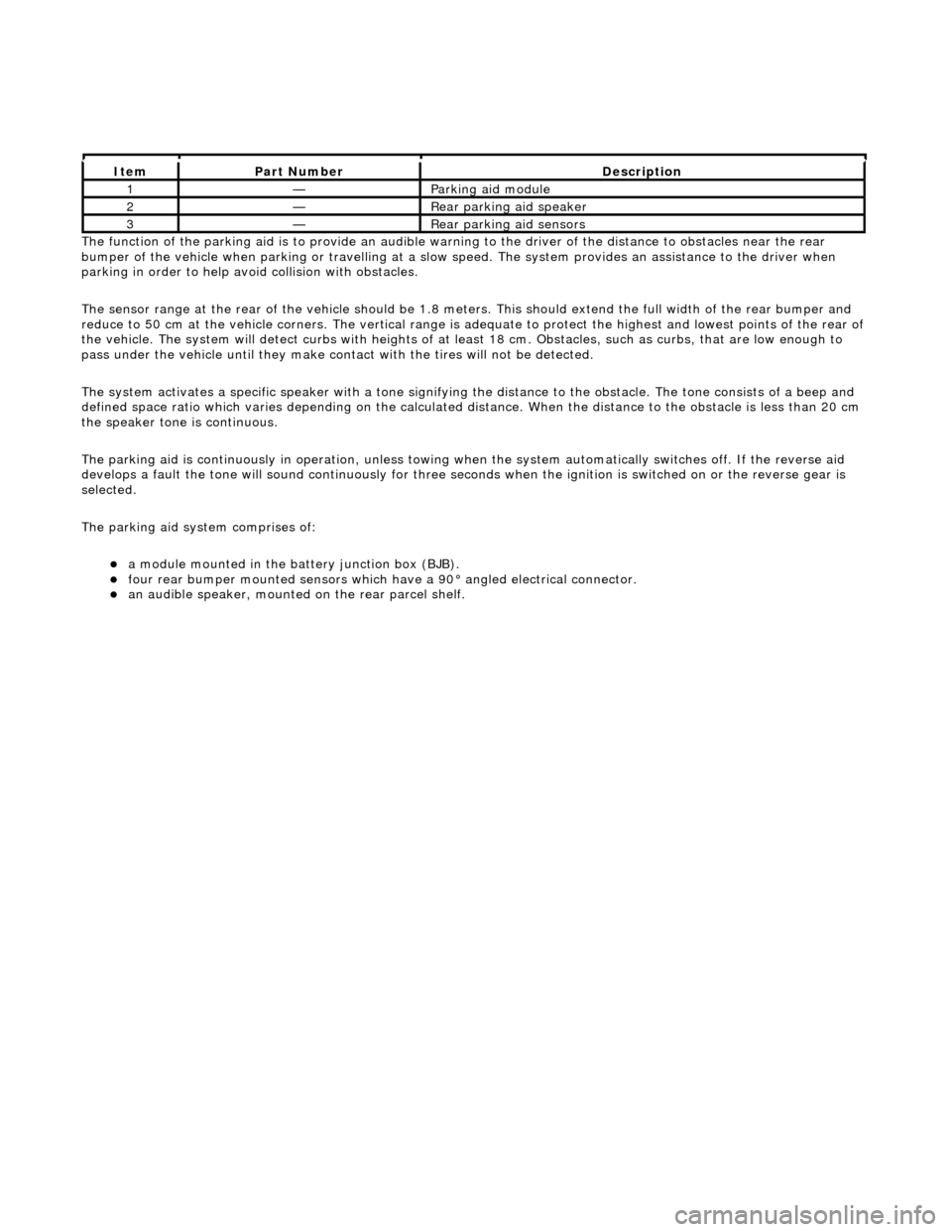
The parking aid system comprises of:
a
module mounted in the batte
ry junction box (BJB).
fou
r rear bumper mounted sensors which have a 90° angled electrical connector.
an audible speaker, moun
ted on
the rear parcel shelf.
It
em
Par
t Number
De
scription
1—Parkin
g aid module
2—Rear
parking aid speaker
3—Rear
parking aid sensors
Page 1883 of 2490
Belt tension is achieved by an automatic tensioner; neither the belt nor the tensioner require service apart from checking
the belt wear indicators at each normal service interval.
The minimum service life of the drive belt is 100,000 miles.
Never apply oil to the belt or to the belt tensioner.
Generator - Charging Circuit
Parts List
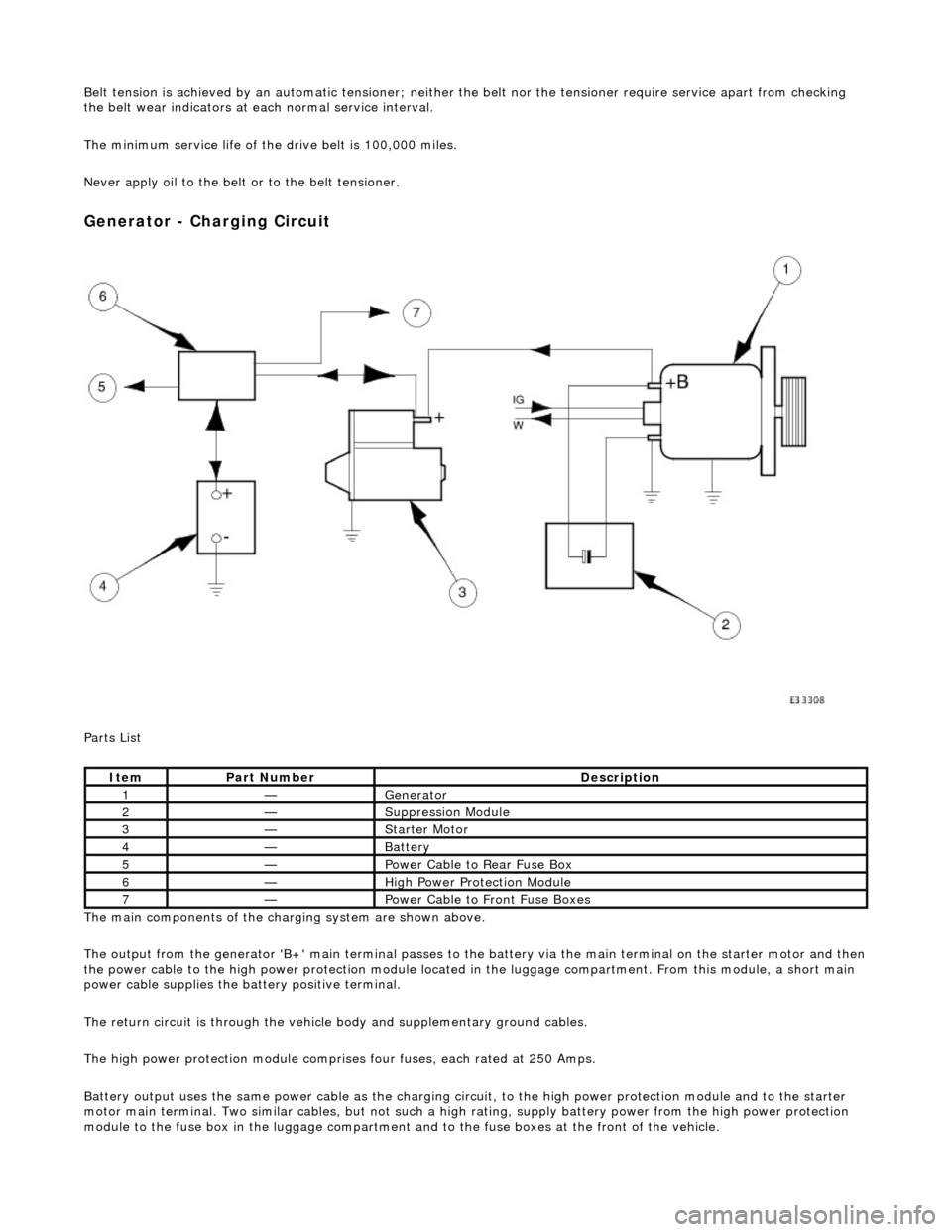
The main components of the charging system are shown above.
The output from the generator 'B+' main te rminal passes to the battery via the main terminal on the starter motor and then
the power cable to the high power protection module located in the luggage compartment. From this module, a short main
power cable supplies the ba ttery positive terminal.
The return circuit is through the vehicle body and supplementary ground cables.
The high power protection mo dule comprises four fuses, each rated at 250 Amps.
Battery output uses the same power cable as the charging circ uit, to the high power protection module and to the starter
motor main terminal. Two similar cables, but not such a high rating, supply battery power from the high power protection
module to the fuse box in the luggage compartment an d to the fuse boxes at the front of the vehicle.
ItemPart NumberDescription
1—Generator
2—Suppression Module
3—Starter Motor
4—Battery
5—Power Cable to Rear Fuse Box
6—High Power Protection Module
7—Power Cable to Front Fuse Boxes
Page 1885 of 2490
If the field were not controlled, the 'B+' output would rise to a level which could damage bulbs and ECMs. The regulator
compares the output voltage to an intern al voltage reference circuit to achieve the controlled output of the generator.
Suppression Module
Although the output from the generator is fi nely controlled and relatively smooth, it is still a pulsed DC output at a varying
frequency proportional to engine speed.
The suppression module damps ou t any ripple which may be sensed on the main output of the generator. This prevents
possible interference via the power supply, affecting the radio reception or, where fitted, the telephone.
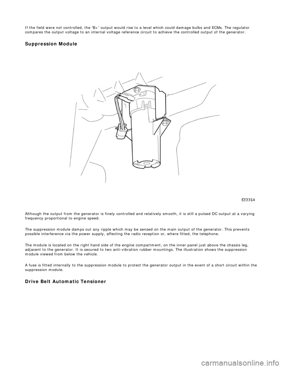
The module is located on the right hand side of the engine compartment, on the inner panel just above the chassis leg,
adjacent to the generator. It is secured to two anti-vibration rubber moun tings. The illustration shows the suppression
module viewed from below the vehicle.
A fuse is fitted internally to the suppression module to protect the generator output in the event of a short circuit within th e
suppression module.
Drive Belt Automatic Tensioner
Page 1886 of 2490
Belt tension is achieved by an automatic tensioner; neither the belt nor the tensioner require service apart from checking
the belt wear indicators at each normal service interval.
The minimum service life of the drive belt is 100,000 miles.
Never apply oil to the belt or to the belt tensioner.
ItemDescription
1New Belt - Minimum Length
2New Belt - Maximum Length
3Replace the Belt
Page 1887 of 2490
Generator and Regulator - Generator
Diagnosis and Testing
Refer to PDU User Guide
Refer to the PDU User Manual for detailed instructions on testing the charging circuit.
When diagnosing the charging ci rcuit, the PDU indicates only whether the generator is charging or not charging. The reason
for this is that the PDU cannot handle the potential full charging current and that the voltage control circuits are located
within the generator assembly, making th em inaccessible by the PDU directly.
It is possible that the battery has failed. In this case, the voltage output at the generator could be correct, but the voltage
at the battery terminals, and therefore the rest of the vehicl e system, will be adversely affected by the faulty battery.
The same result is given by the PDU if the battery is faulty (generator not faulty), wiring fault (damaged or severe corrosion
at the terminals) or if th e generator is at fault.
Inspection and Verification
The following manual tests help to pinpoint which component is at fault.
Testing the Battery Circuit
Using the Vehicle Battery
Remove the battery cover.
Ensure that all electrical loads are swit ched OFF and that the engine is cool.
Start the engine and allow to IDLE.
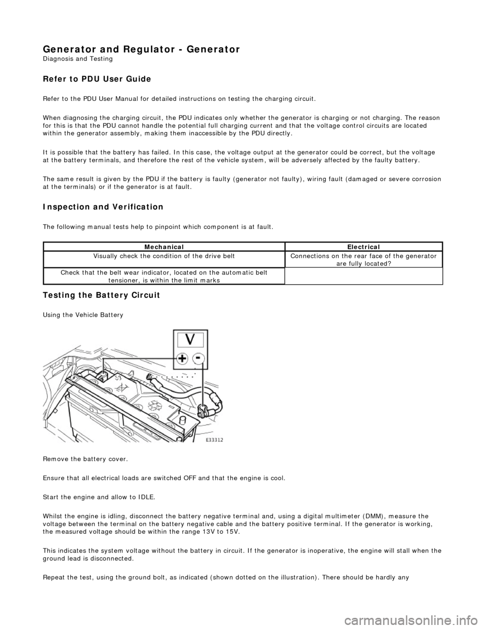
Whilst the engine is idling, disconnect the battery negative terminal and, using a digital multimeter (DMM), measure the
voltage between the terminal on the batter y negative cable and the battery positive terminal. If the generator is working,
the measured voltage should be within the range 13V to 15V.
This indicates the system voltage without the battery in circuit. If the generator is inoperative, the engine will stall when t he
ground lead is disconnected.
Repeat the test, using the ground bolt, as indicated (shown dotted on the illustration). There should be hardly any
MechanicalElectrical
Visually check the condition of the drive beltConnections on the rear face of the generator
are fully located?
Check that the belt we ar indicator, located on the automatic belt
tensioner, is within the limit marks
Page 1908 of 2490
Antenna - Antenna
Description and Operation
The electrically operated antenna operates automatically when the Ignition switch is set to position 1 or 2, and the radio
cassette player is switched on , regardless of the status of the tape or CD mode switch.
The antenna motor is protected by a 10A fuse, F9, located in the trunk fuse-box.
Page 1962 of 2490
Interior Lighting - Interior Lighting
Description and Operation
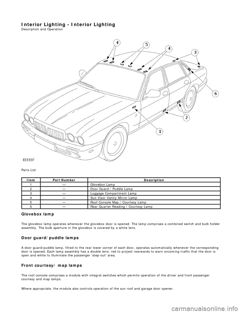
Parts List
Glovebox lamp
The glovebox lamp operates whenever the glovebox door is opened. The lamp comprises a combined switch and bulb holder assembly. The bulb aperture in the glovebox is covered by a white lens.
Door guard/puddle lamps
A door guard/puddle lamp, fitted to the rear lower corner of each door, operates automatically whenever the corresponding
door is opened. Each lamp assembly has a double lens; red to project rearwards to warn oncoming traffic that the door is
open and white to illuminate the passenger 'step-out' area.
Front courtesy/ map lamps
The roof console comprises a module with integral switches which permits operation of the dr iver and front passenger
courtesy and map lamps.
Where appropriate, the module also controls operation of the su n roof and garage door opener.
ItemPart NumberDescription
1—Glovebox Lamp
2—Door Guard / Puddle Lamp
3—Luggage Compartment Lamp
4—Sun Visor Vanity Mirror Lamp
5—Roof Console Map / Courtesy Lamp
6—Rear Quarter Reading / Courtesy Lamp