Page 1491 of 2490
Automatic Transmission/Transaxle External Controls - 4.0L NA V8 -
AJ27/3.2L NA V8 - AJ 26 - Selector Lever Indicator Assembly
Removal and Installation
Removal
Installation
1. Disconnect battery ground cable.
Remove the battery cover.
2. Remove the selector lever knob, 44.15.06.
3. Remove the J-gate surround, Section 501-05.
4. Remove the console finisher ve neer panel, Section 501-12.
5. Remove the selector indicator module screws.
6. Remove the selector indicator module.
1. Free the D to 4 switch harness multiplug from the mounting bracket and disc onnect the multiplug.
2. Displace the P switch multiplug from the mounting bracket.
3. Route the D to 4 harnes s from under the P switch
harness.
1. Installation is the revers e of the removal procedure
2. Connect the battery and fit the battery cover.
Reset the radio and the clock.
Page 1492 of 2490
Automatic Transmission/Transaxle External Controls - 4.0L NA V8 -
AJ27/3.2L NA V8 - AJ26 - Se lector Lever Indicator Disc
Removal and Installation
Removal
Installation
1. Disconnect battery ground cable.
Remove the battery cover.
2. Remove the selector indicator module; 44.15.14.
3. Remove the selector indicator module disc.
Remove the disc retaining screw.
1. Installation is th e reverse of the re moval procedure.
2. Connect the battery and fit the battery cover.
Reset the radio and the clock.
Page 1493 of 2490
Automatic Transmission/Transaxle External Controls - 4.0L NA V8 -
AJ27/3.2L NA V8 - AJ26 - Selector Lever Switch
Removal and Installation
Removal
Installation
1. Disconnect battery ground cable.
Remove the battery cover.
2. Remove the gear shift knob, (44.15.06).
3. Remove the console finisher veneer panel, (76.47.26).
4. Remove the 'J Gate' surroun d for access, (76.25.24).
5. Remove the D to 4 switch.
Press the retaining tangs to release.
1. Fitting a new D to 4 switch is the reverse of the removal
procedure.
2. Connect the battery and fit the battery cover.
Reset the radio and the clock.
Page 1494 of 2490
Automatic Transmission/Transaxle External Controls - 4.0L NA V8 -
AJ27/3.2L NA V8 - AJ26 - Selector Lever Knob
Removal and Installation
Removal
Installation
1. Remove the select or lever knob.
1. Slacken the ferrule, rotate clock-wise.
2. Rotate the knob coun ter-clockwise to remove.
1. Refer to the illustration
1. Fit the knob.
2. Tighten the ferru le to the specified torque figure.
Page 1495 of 2490
Automatic Transmission/Transaxle External Controls - 4.0L NA V8 -
AJ27/3.2L NA V8 - AJ26 - Selector Lever Assembly
Disassembly and Assembly
1. Disconnect battery ground cable.
Remove the battery cover.
2. Remove the shift le ver knob, 44.15.06.
3. Remove the J-gate surround, Section 501-05.
4. Remove the console finisher ve neer panel, Section 501-12.
5. Remove the center console assembly, Section 501-12.
6. Remove the indicator module, 44.15.14.
7. Detach the selector cable from the gear shift assembly.
1. Remove the inner cable to selector lever nut.
2. Slacken one outer cable locknut, keeping one positioned for reference on reassembly.
8. Remove the gear shift assembly.
Remove the four fixings.
9. Remove the slide plate.
Remove the four screws.
Page 1499 of 2490
Automatic Transmission/Transaxle External Controls - 4.0L SC V8 - AJ26 -
External Controls
Description and Operation
Introduction
Operator gearshift control is effected by:
The selector lever Accelerator pedal position Kickdown The mode switch
Operator's Selector Module ('J' Gate)
Page 1504 of 2490

Automatic Transmission/Transaxle External Controls - 4.0L SC V8 - AJ26 -
External Controls
Diagnosis and Testing
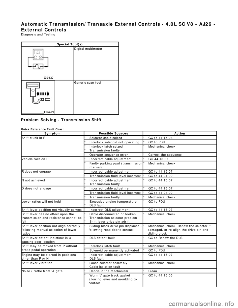
Problem Solving - Transmission Shift
Quick Reference Fault Chart
Special Tool(s)
Digital multimeter
Generic scan tool
SymptomPossible SourcesAction
Shift stuck in P Selector cable seized
*GO to 44.15.08
*
Interlock solenoid not operating
*GO to PDU
*
Interlock latch seized
Transmission faulty
*
*Mechanical check
*
Operator sequence error
*Correct the sequence
*
Vehicle rolls on P Incorrect cable adjustment
*GO 44.15.07
*
Faulty parking pawl (transmission internal)
*Mechanical check
*
R does not engageIncorrect cable adjustment
*GO to 44.15.07
*
Transmission fluid level incorrect
*GO to 44.24.02
*
N not achievedIncorrect cable adjustment
Transmission faulty
*
*GO to 44.15.07
*
D does not engageIncorrect cable adjustment *GO to 44.15.07
*
Transmission fluid level incorrect
*GO to 44.24.02
*
Transmission faulty
*Mechanical check
*
Lower ratios will not holdExcessive engine temperature
DLS fault
*
*GO to PDU
*
Shift lever position not visually correctIncorrect DLS adjustment
*GO to 44.15.07
*
Shift lever has no effect upon the
transmission and resistance cannot be
feltCable disconnected or broken
Transmission selector problem
Shift lever drive pin adrift
*
*
*Mechanical check
*
Shift lever position not align correctly
following manual selection of lower
ratiosSliding block drive pin displaced - following road debris contact
*Mechanical check. Renew the selector if
damaged, or re-align the drive pin and
sliding block
*
Shift lever detent indistinct in 3
causing poor locationDLS detent fault
*GO to Renew the DLS
*
Shift may be moved from P without
brake pedal operationInterlock latch fault
*Mechanical check
*
Solenoid permanently activated
*GO to PDU
*
Engine may be started in positions
other than P or N Incorrect cable adjustment
DLS fault
*
*GO to 44.15.07
*
Shift lever vibrationLoose selector assembly
Cable isolation fault
*
*Mechanical check
*
Noise / rattle from 'J' gateDebris in the mechanism
*Clean
*
Worn 'J' gate track gasket
allowing lever and moulding to
contact
*GO to 44.15.05
*
Page 1508 of 2490
Automatic Transmission/Transaxle External Contro ls - 4.0L SC V8 - AJ26 -
Brake Shift Interlock Actuator Manual Override
General Procedures
1. To override the gearshift interlock:
1. Unscrew the release catch blanking plug.
2. Insert the ignition key into the aperture, depress the release catch and simultan eously move the gear
selector lever from the Park position. The lever will
only move approximately 25 mm with the key
inserted.
3. Remove the ignition key and replace the blanking plug.