Page 2292 of 2490
Handles, Locks, Latches and Entry Systems - Luggage Compartment Lid
Release Switch
Removal and Installation
Removal
1. Remove trunk lamp assemblies. Refer to 86.45.16.
2. Remove covers from the two tr unk latch finisher securing
bolts and slacken and remove bolts.
3. Remove latch finisher from trunk.
4. Remove and discard the four fast eners securing rear of trunk lid liner and position liner for access.
5. Release trunk release button harness connector from retaining
clip and disconnect connector.
6. Slacken and remove the trunk u pper trim finisher securing
nuts.
Page 2293 of 2490
Installation
7. Position upper trim finisher fo r access and withdraw release
button harness grommet from trunk lid aperture.
8. Position upper trim finisher for access and slacken and remove
release button securing screws.
9. Withdraw release button asse mbly from trim finisher.
1. Position trunk release button as sembly on trim finisher and
install securing screws.
2. Position trim finisher/release button assembly at trunk lid and
route harness through lid aperture.
3. Position grommet over harness and install in trunk lid aperture.
4. Position trim finisher/release button assembly on trunk lid and
install securing nuts.
5. Connect release button harness connector and install on
retaining clip.
6. Reposition rear of trunk lid liner and secure with new fasteners.
7. Position lock finisher and install securing bolts.
8. Install covers over finisher securing bolts.
9. Install trunk lights. Refer to 86.45.16.
Page 2306 of 2490

Wipers and Washers - Wipers and Washers
Description and Operation
Windshield Wiper
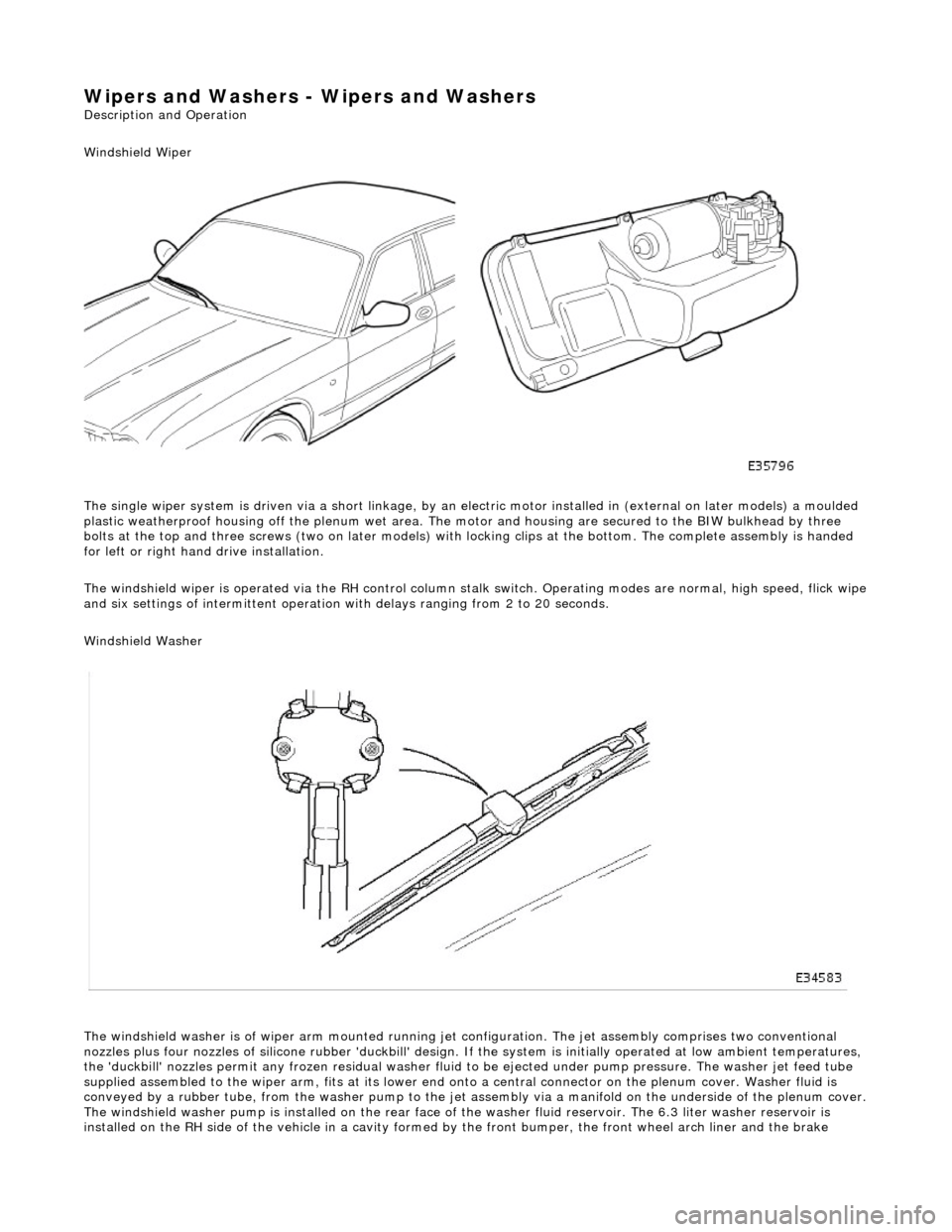
The single wiper system is driven via a sh ort linkage, by an electric motor installed in (external on later models) a moulded
plastic weatherproof housing o ff the plenum wet area. The motor and housing are secured to the BIW bulkhead by three
bolts at the top and three screws (two on later models) with locking clips at the bottom. The complete assembly is handed
for left or right hand drive installation.
The windshield wiper is operated via the RH control column stalk switch. Operating modes are normal, high speed, flick wipe
and six settings of intermittent operation with delays ranging from 2 to 20 seconds.
Windshield Washer
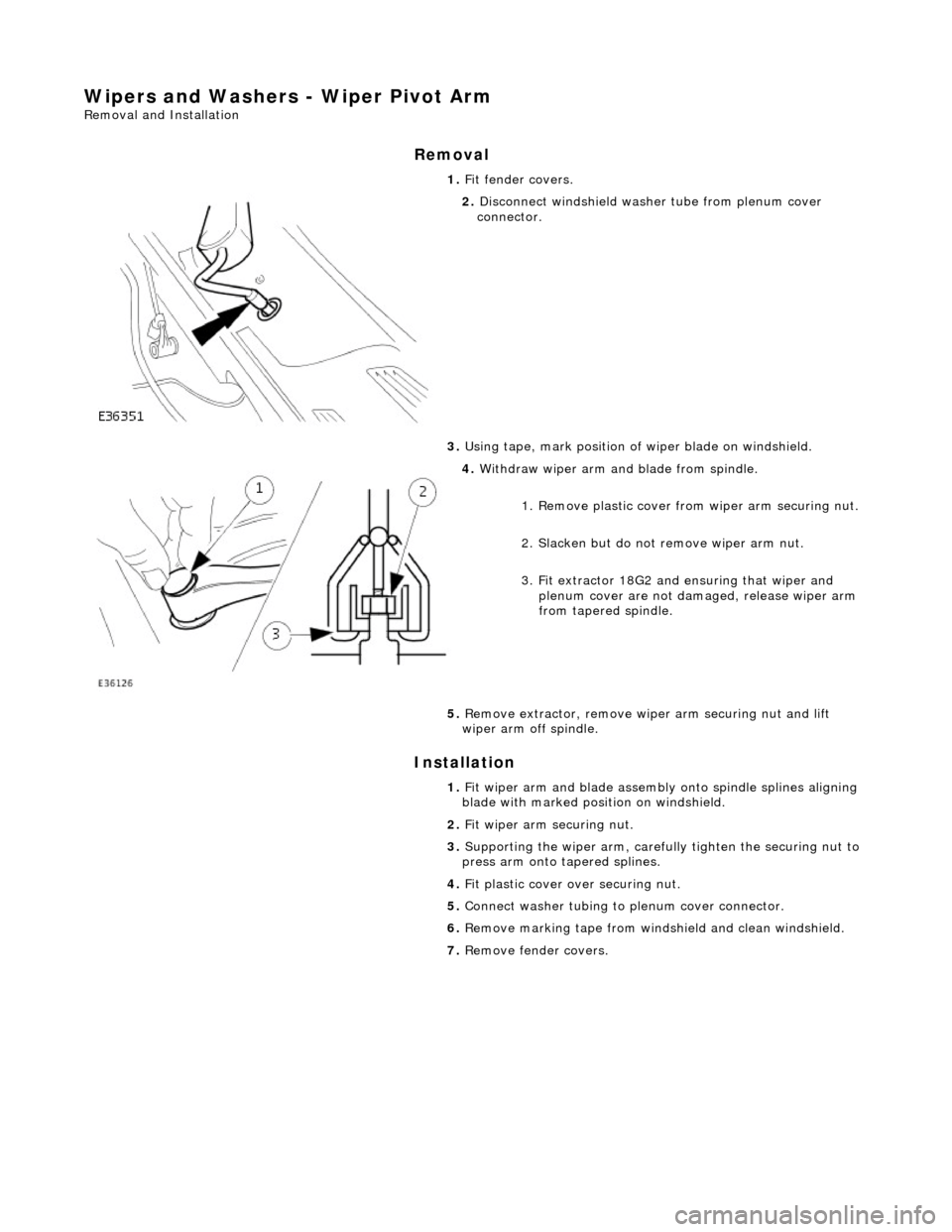
The windshield washer is of wiper arm mounted running jet configuration. The je t assembly comprises two conventional
nozzles plus four nozzles of silicone rubbe r 'duckbill' design. If the system is initially operated at low ambient temperatures ,
the 'duckbill' nozzles permit an y frozen residual washer fluid to be ejected un der pump pressure. The washer jet feed tube
supplied assembled to the wiper ar m, fits at its lower end onto a central connector on the pl enum cover. Washer fluid is
conveyed by a rubber tube, from the washer pump to the jet assembly via a manifold on the underside of the plenum cover.
The windshield washer pump is installed on the rear face of the washer fluid reservoir. The 6.3 liter washer reservoir is
installed on the RH side of th e vehicle in a cavity formed by the front bu mper, the front wheel arch liner and the brake
Page 2312 of 2490
Wipers and Washers - Rain Sensor
Removal and Installation
Removal
Installation
1. Remove battery cover and disc onnect ground cable from
battery terminal. Refer to 86.15.19.
2. Remove cover from rear view mirror base.
3. Disconnect flying lead from sensor unit connector.
4. Using a thin plastic blade, carefully remove sensor unit from
windshield.
5. Using an approved solvent, re move residual adhesive from
windshield.
6. If sensor is to be re-used, remove adhesive pad and clean base
of unit using an approved solvent.
1. Install new ad hesive pad.
Peel backing paper from one si de of new adhesive pad.
Position pad correctly in clear area of obscuration band
and press firmly to fully seat.
Page 2327 of 2490

Wipers and Washers - Wiper Pivot Arm
Removal and Installation
Removal
Installation
1.
Fit fender covers.
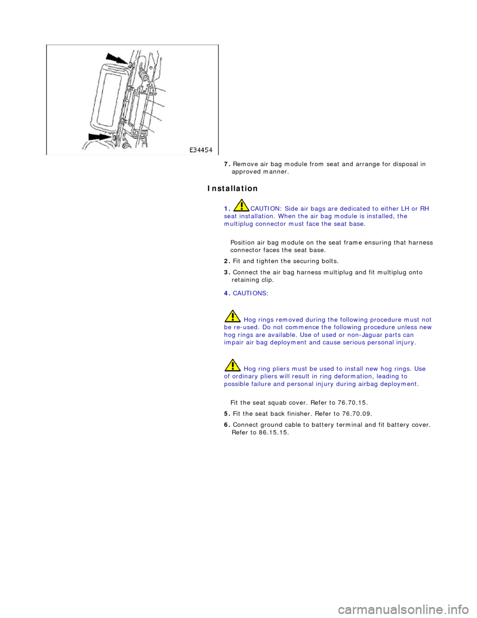
2. Disconnect windshield washer tube from plenum cover
connector.
3. Using tape, mark po sition of wiper blade on windshield.
4. Withdraw wiper arm and blade from spindle.
1. Remove plastic cover fro m wiper arm securing nut.
2. Slacken but do not remove wiper arm nut.
3. Fit extractor 18G2 and ensuring that wiper and
plenum cover are not dama ged, release wiper arm
from tapered spindle.
5. Remove extractor, remove wi per arm securing nut and lift
wiper arm off spindle.
1. Fit wiper arm and blade assembly onto spindle splines aligning
blade with marked position on windshield.
2. Fit wiper arm securing nut.
3. Supporting the wiper ar m, carefully tighten the securing nut to
press arm onto tapered splines.
4. Fit plastic cover over securing nut.
5. Connect washer tubing to plenum cover connector.
6. Remove marking tape from windshield and clean windshield.
7. Remove fender covers.
Page 2378 of 2490

Installation
7. Remove air bag module from seat and arrange for disposal in
approved manner.
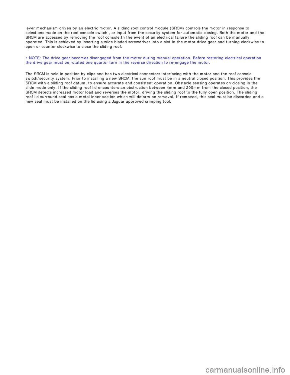
1. CAUTION: Side air bags are de dicated to either LH or RH
seat installation. When the air bag module is installed, the
multiplug connector must face the seat base.
Position air bag module on the seat frame ensuring that harness
connector faces the seat base.
2. Fit and tighten the securing bolts.
3. Connect the air bag harness mult iplug and fit multiplug onto
retaining clip.
4. CAUTIONS:
Hog rings removed during the following procedure must not
be re-used. Do not commence the following procedure unless new hog rings are availabl e. Use of used or non-Jaguar parts can
impair air bag deployment and cause serious personal injury.
Hog ring pliers must be used to install new hog rings. Use
of ordinary pliers will result in ring deformation, leading to
possible failure and personal in jury during airbag deployment.
Fit the seat squab cover. Refer to 76.70.15.
5. Fit the seat back finisher. Refer to 76.70.09.
6. Connect ground cable to battery terminal and fit battery cover.
Refer to 86.15.15.
Page 2420 of 2490

lever mechanism driven by an electric motor. A sliding roof control module (SRCM) controls the motor in response to
selections made on the roof console switch , or input from the security system for automatic closing. Both the motor and the SRCM are accessed by removing the roof console.In the event of an electrical failure the sliding roof can be manually
operated. This is achieved by inserting a wide bladed screwdriver into a slot in the motor drive gear and turning clockwise to open or counter clockwise to close the sliding roof.
• NOTE: The drive gear becomes disengaged from the motor during manual operation. Before restoring electrical operation
the drive gear must be rotated one quarter turn in the reverse direction to re-engage the motor.
The SRCM is held in position by clips and has two electrical connectors in terfacing with the motor and the roof console
switch/security system. Prior to installing a new SRCM, the sun ro of must be in a neutral closed position. This provides the
SRCM with a sliding roof datum, to ensure accurate and consistent operation. Obstacle sensin g operates on closing in the
slide mode only. If the sliding roof lid encounters an ob struction between 4mm and 200mm from the closed position, the
SRCM detects increased motor load and reve rses the motor, driving the sliding roof to the fully open position. The sliding
roof lid surround seal has a metal inner sect ion which will deform on removal. If removed, this seal must be discarded and a
new seal must be installed on the lid using a Jaguar approved crimping tool.
Page 2422 of 2490
8. Remove generator front cooling duct.
Remove bolt.
Move duct rearwards to rele ase tang from undertray.
Release front duct from rear vertical duct.
9. Remove scrivets or screws se curing undertray to bumper
cover. Discard scrivets.
10. Remove and discard tiestrap securing undertray to body
brace.
11. At each side of vehicle, remo ve and discard scrivet securing undertray to wheelarch liner.
12. Remove undertray from vehicle.
13. Remove both front road wheels. Refer to Section 100-02.
14. Remove both front road springs. Refer to 60. 20.02.
15. Disconnect wheel speed sensor harness connectors.