Page 2028 of 2490
Front End Body Panels - Cowl Panel Grille
Removal and Installation
Installation
1.
Open the hood and fit fender covers.
2. Remove the wiper arm and blade assembly. Refer to
84.15.44.90.
3. Slacken and remove the five pl enum cover securing screws.
4. Position the plenum cover for access and disconnect windshield
washer pump tube from pl enum cover connector.
5. Remove plenum cover from vehicle.
6. Remove screenwasher conne ctor from plenum cover.
7. Remove plenum cover spacers,
1. Fit washer hose connector to plenum cover.
2. Fit and fully seat plenum cover spacers.
3. Position plenum cover for access and fit windshield washer
pump to plenum connector hose.
4. Fit plenum cover ensuring that it seats correctly in upper seal.
5. Fit and tighten securing screws.
6. Fit washer hose to plenum connector.
7. Fit wiper arm and blade. Refer to 84.15.44.90.
8. Close hood and remove fender covers.
Page 2034 of 2490

Body Closures - Body Closures
Description and Operation
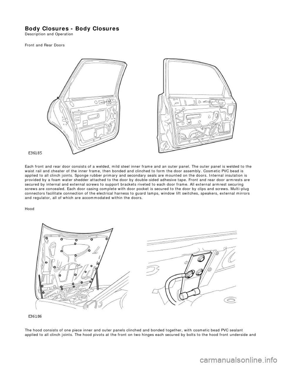
Front and Rear Doors
Each front and rear door consists of a welded, mild steel inner frame and an outer panel. The outer panel is welded to the
waist rail and cheater of the inner frame, then bonded and clinched to fo rm the door assembly. Cosmetic PVC bead is
applied to all clinch joints. Sponge rubber primary and secondary seals are mo unted on the doors. Internal insulation is
provided by a foam water shedder attached to the door by double-sided adhesive tape. Front and rear door armrests are
secured by internal and external screws to support brackets riveted to each door frame . All external armrest securing
screws are concealed. Each door casing complete with door po cket is secured to the door by clips and screws. Multi-plug
connectors facilitate connection of the electrical harness to guard lamps, window lift switches, speakers, external mirrors
and regulator, all of which are accommodated within the doors.
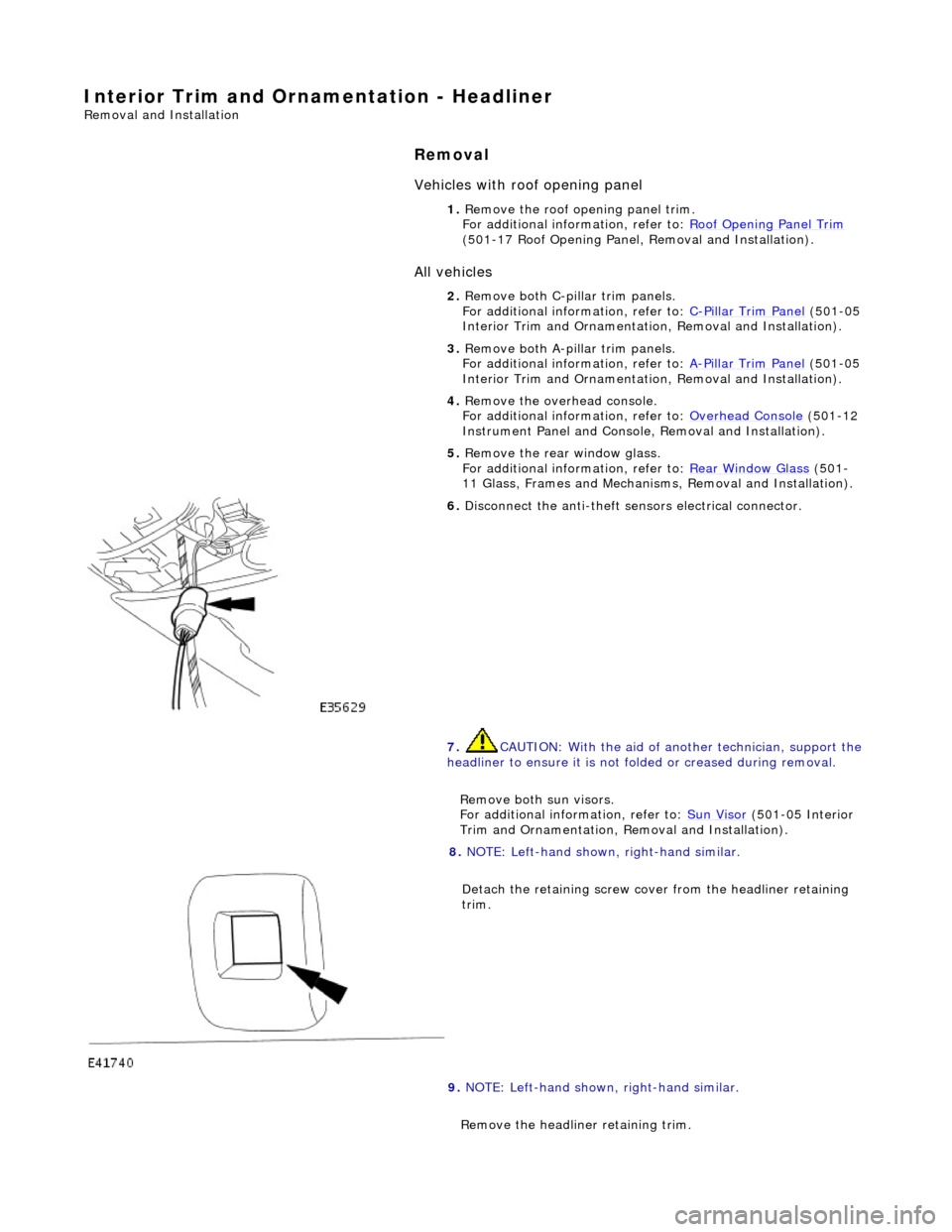
Hood
The hood consists of one piece inner an d outer panels clinched and bonded toge ther, with cosmetic bead PVC sealant
applied to all clinch joints. The hood pivo ts at the front on two hinges each secured by bolts to the hood front underside and
Page 2059 of 2490
Interior Trim and Ornamentation - C-Pillar Trim Panel
Removal and Installation
Removal
1. Remove the passenger assist handle.
For additional information, refer to: Passenger Assist Handle
(501-05 Interior Trim and Ornamentation, Removal and
Installation).
2. Detach the rear courtesy/reading light.
3. Remove the rear courtesy/reading light.
Disconnect the electrical connector.
4. Detach the door aperture weatherstrip.
5. Detach the C-pillar trim panel fi r tree fasteners from the BIW.
6. Remove the C-pillar trim pa nel and discard the fir tree
fasteners.
Page 2076 of 2490

Interior Trim and Ornamentation - Headliner
Removal and Installation
Removal
Vehicles with roof opening panel
All vehicles
1. Remove the roof opening panel trim.
For additional information, refer to: Roof Opening Panel Trim
(501-17 Roof Opening Panel, Removal and Installation).
2. Remove both C-pill ar trim panels.
For additional information, refer to: C
-Pillar Trim Panel (501-05
Interior Trim and Ornamentatio n, Removal and Installation).
3. Remove both A-pill ar trim panels.
For additional information, refer to: A
-Pillar Trim Panel (501-05
Interior Trim and Ornamentatio n, Removal and Installation).
4. Remove the overhead console.
For additional information, refer to: Overhead Console
(501-12
Instrument Panel and Console, Removal and Installation).
5. Remove the rear window glass.
For additional information, refer to: Rear Window Glass
(501-
11 Glass, Frames and Mechanis ms, Removal and Installation).
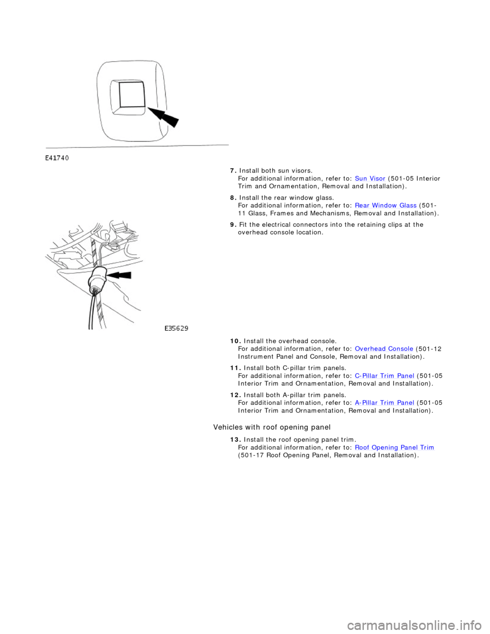
6. Disconnect the anti-theft se nsors electrical connector.
7. CAUTION: With the aid of an other technician, support the
headliner to ensure it is not folded or creased during removal.
Remove both sun visors.
For additional information, refer to: Sun Visor
(501-05 Interior
Trim and Ornamentation, Re moval and Installation).
8. NOTE: Left-hand shown, right-hand similar.
Detach the retaining screw cove r from the headliner retaining
trim.
9. NOTE: Left-hand shown, right-hand similar.
Remove the headline r retaining trim.
Page 2077 of 2490
Installation
All vehicles
Remove the retaining screw.
10. With the aid of another tech nician, lower the headliner.
11. With the aid of another techni cian, remove the headliner.
12. NOTE: Left-hand shown, right-hand similar.
Detach the anti-theft sensors.
13. NOTE: Left-hand shown, right-hand similar.
Remove the anti-t heft sensors.
1. Disconnect the electrical connector.
1. NOTE: Left-hand shown, right-hand similar.
Page 2078 of 2490
Install the anti-theft sensors. 1. Connect the electrical connector.
2. NOTE: Left-hand shown, right-hand similar.
Attach the anti-theft sensors.
3. CAUTION: With the aid of an other technician, support the
headliner.
Install the headliner.
4. With the aid of another tech nician, raise the headliner.
5. CAUTION: Support the headliner to ensure it is not folded or creased during installation.
• NOTE: Left-hand shown, right-hand similar.
Install the headliner retaining trims.
Install the retaining screw.
6. NOTE: Left-hand shown, right-hand similar.
Attach the screw cover.
Page 2079 of 2490

Vehicles with roof opening panel
7. Install both sun visors.
For additional information, refer to: Sun Visor (501-05 Interior
Trim and Ornamentation, Re moval and Installation).
8. Install the rear window glass.
For additional information, refer to: Rear Window Glass
(501-
11 Glass, Frames and Mechanis ms, Removal and Installation).
9. Fit the electrical connectors into the retaining clips at the
overhead console location.
10. Install the overhead console.
For additional information, refer to: Overhead Console
(501-12
Instrument Panel and Console, Removal and Installation).
11. Install both C-pillar trim panels.
For additional information, refer to: C
-Pillar Trim Panel (501-05
Interior Trim and Ornamentatio n, Removal and Installation).
12. Install both A-pillar trim panels.
For additional information, refer to: A
-Pillar Trim Panel (501-05
Interior Trim and Ornamentatio n, Removal and Installation).
13. Install the roof opening panel trim.
For additional information, refer to: Roof Opening Panel Trim
(501-17 Roof Opening Panel, Removal and Installation).
Page 2100 of 2490

Exterior Trim and Ornamentation - A-Pillar Moulding LH
Removal and Installation
Removal
Installation
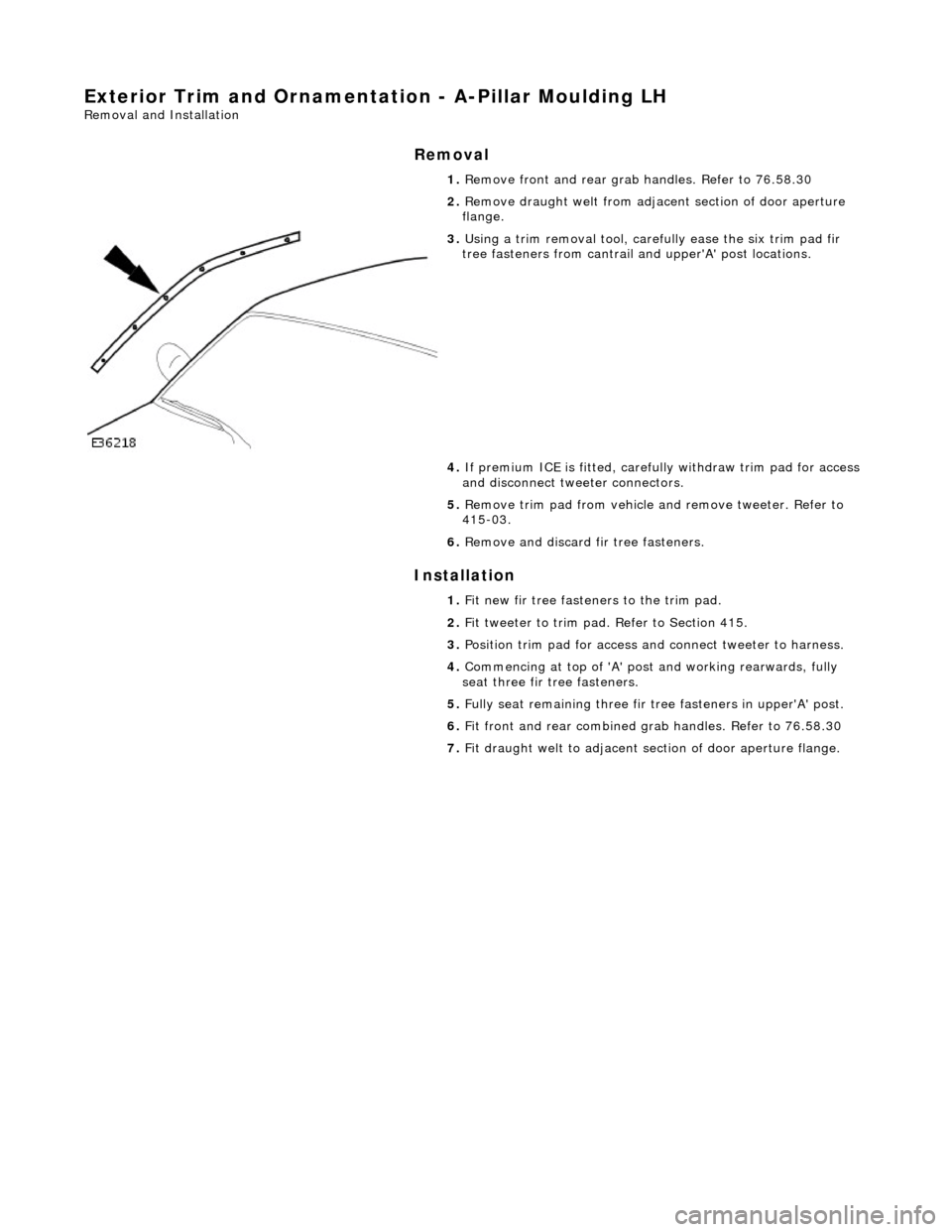
1.
Remove front and rear grab handles. Refer to 76.58.30
2. Remove draught welt from adjace nt section of door aperture
flange.
3. Using a trim removal tool, carefu lly ease the six trim pad fir
tree fasteners from cantrail an d upper'A' post locations.
4. If premium ICE is fitt ed, carefully withdraw trim pad for access
and disconnect tweeter connectors.
5. Remove trim pad from vehicle an d remove tweeter. Refer to
415-03.
6. Remove and discard fir tree fasteners.
1. Fit new fir tree fasten ers to the trim pad.
2. Fit tweeter to trim pad. Refer to Section 415.
3. Position trim pad for access and connect tweeter to harness.
4. Commencing at top of 'A' post and working rearwards, fully
seat three fir tree fasteners.
5. Fully seat remaining three fir tr ee fasteners in upper'A' post.
6. Fit front and rear combined gr ab handles. Refer to 76.58.30
7. Fit draught welt to adjacent section of door aperture flange.