Page 1607 of 2490
With EM010 and EM012 disconnected, measure the
voltage between EM010/023 and EM012/022. 1
Is the voltatage 0 (zero) V?
Yes GO to F17
No Inspect harness / connecto rs EM010, EM012 and EM023
for corrosion, damaged / pushed back pins.
Repair as required an d reconnect plug(s).
GO to F19
F17: CHECK FOR SHORT TO B+ AT O2 SENSOR HEATER
Page 1608 of 2490
Ignition switch to position 0 1
Remove EMS fuse F14. 2
Disconnect EM010 and EM015. 3
Using a link lead, bridge EM010/016 and EM010/022. 4
Measure the voltage between EM010/023 and
EM015/001. 5
Is the voltage 0 (zero) V?
Yes Replace EMS fuse F14 but retain link lead
GO to F18
No Inspect connectors EM010, EM015, and EM023 for
corrosion, damaged / pushed back pins or repair the
harness; reconnect plug(s).
GO to F19
F18: CHECK B+ AT O2 SENSOR HEATER CIRCUIT
Page 1760 of 2490

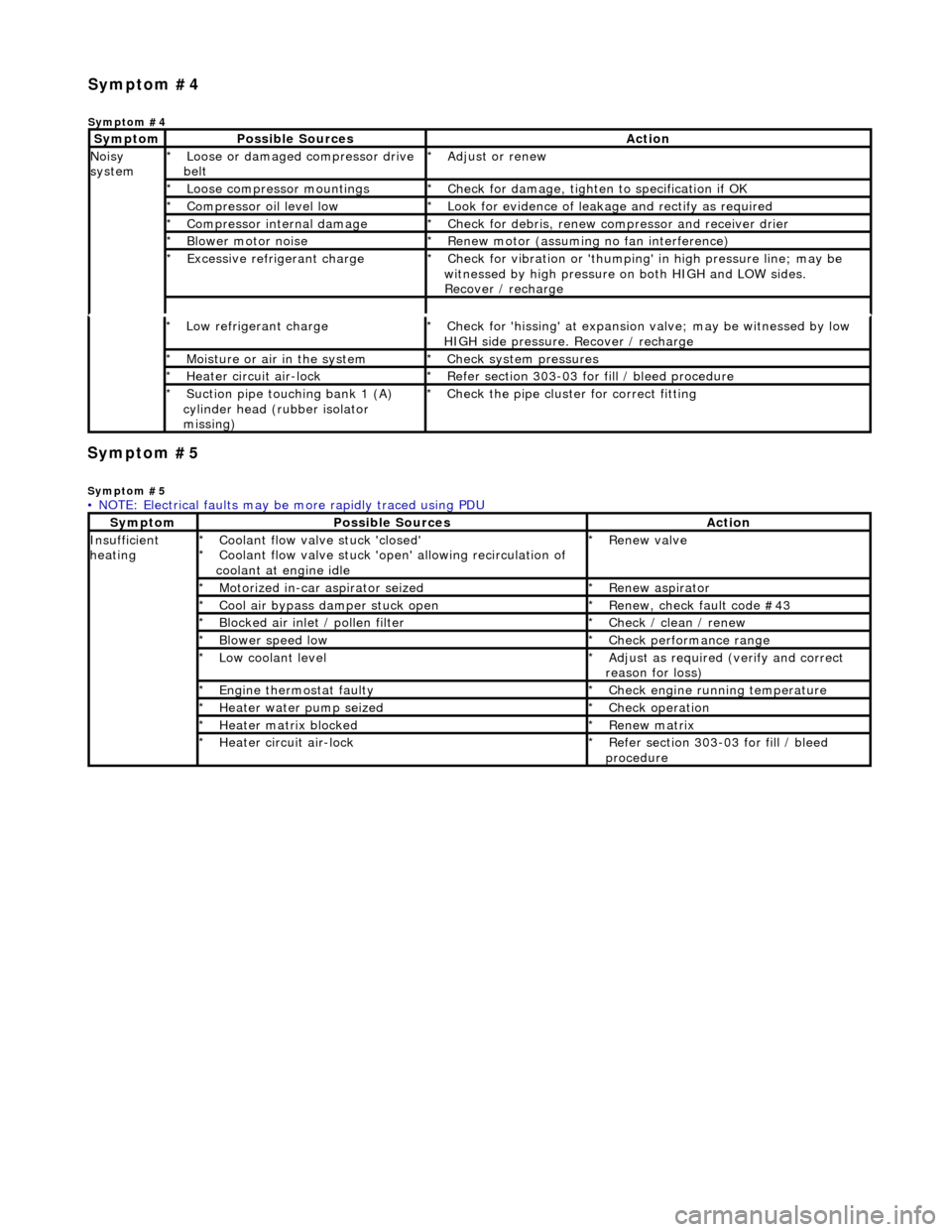
Symp
tom #5
Sy
m
ptom #5
Low r
e
frigerant charge
*
Check f or 'hissi
ng' at expansion
valve; may be witnessed by low
HIGH side pressure. Recover / recharge
*
Moi
s
ture or air in the system
*
Chec k syst
em pressures
*
Heat er ci
rcuit air-lock
*
R e
fer section 303-03 for fill / bleed procedure
*
Suct ion
pipe touching bank 1 (A)
cylinder head (rubber isolator
missing)
*
Check the pi
pe cluster for correct fitti
ng
*
• NOTE: Electrical faults may be more rapidly traced using PDU
Sym
ptom
Possib
l
e Sources
Acti
o
n
Insuffi
ci
ent
heating
Coo l
ant flow valve stuck 'closed'
Coolant flow valve stuck 'open' allowing recirculation of
coolant at engine idle
*
*
Re
new v
alve
*
Motorized in-car aspirator sei zed
*R e
new aspirator
*
Coo l
air bypass damper stuck open
*
Re new,
check fault code #43
*
B l
ocked air inlet / pollen filter
*
Chec k / cl
ean / renew
*
B l
ower speed low
*
Check performance range
*
Low cool ant
level
*
Adjust as req u
ired (verify and correct
reason for loss)
*
Engine
t
hermostat faulty
*
Check engine r u
nning temperature
*
Heater water pump seized
*Chec k op
eration
*
Heater ma trix
blocked
*
Re new m
atrix
*
Heater circui t
air-lock
*
R e
fer section 303-03 for fill / bleed
procedure
*
Sym
p
tom #4
Sym
ptom #4
Sy
m
ptom
Possib
l
e Sources
Acti
o
n
No
i
sy
system
Loose or damaged compressor drive
belt
*Adjust or r
e
new
*
Loose compressor mountings
*Check f o
r damage, tighten to specification if OK
*
Compressor oil level l
ow
*
Look for evidence of l
eakag
e and rectify as required
*
Compressor internal dama ge
*Check f o
r debris, renew compressor and receiver drier
*
B l
ower motor noise
*
Re new m
otor (assuming no fan interference)
*
Excessive refrige rant charge
*Check f o
r vibration or 'thumping'
in high pressure line; may be
witnessed by high pressure on both HIGH and LOW sides.
Recover / recharge
*
Page 1769 of 2490

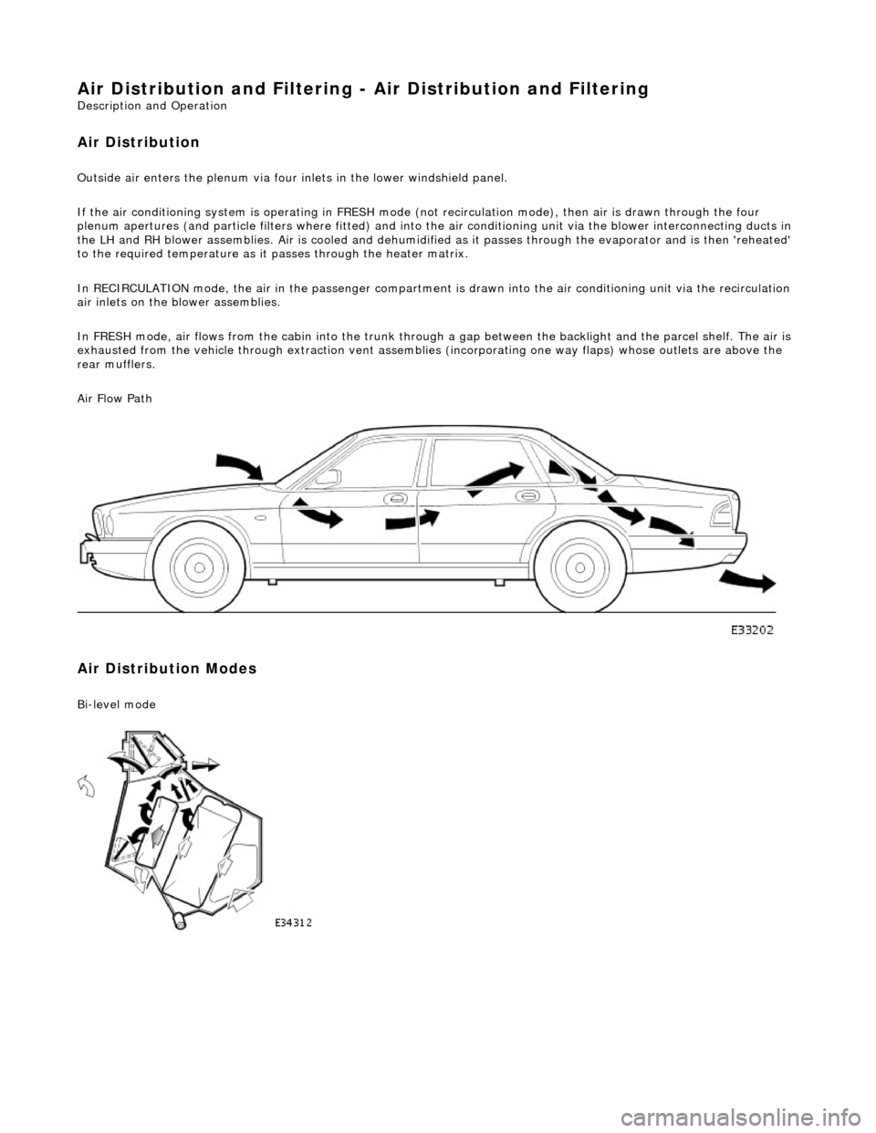
Air Distribution and Filtering - Air Distri
bution and Filtering
Description an
d Operation
Air Distribution
Ou
tside air enters the plen
um via four inlets in the lower windshield panel.
If the air conditioning system is operating in FRESH mode (not recirculation mode), then air is drawn through the four
plenum apertures (and particle filters where fitted) and into the air conditioni ng unit via the blower interconnecting ducts in
the LH and RH blower assemblies. Air is c ooled and dehumidified as it passes through the evaporator and is then 'reheated'
to the required temperature as it passes through the heater matrix.
In RECIRCULATION mode, the air in the pass enger compartment is drawn into the air conditioning unit via the recirculation
air inlets on the blower assemblies.
In FRESH mode, air flows from the cabin into the trunk through a gap between the backlight and the parcel shelf. The air is
exhausted from the vehicle through extraction vent assemblies (incorporating one way flaps) whose outlets are above the
rear mufflers.
Air Flow Path
Air Distribution Modes
Bi
-level mode
Page 1774 of 2490
I n
strument Pane
l Air Outlets
Ite
m
De
scr
iption
1Ai
r i
nlet - from RH blower (LH opposite, not shown)
2Ai
r outl
et - instrument
panel center vents
3Air ou
tlet - defog
4Ai
r outl
et - instru
ment panel LH and RH side vents
5Air outl
et - footwell
6Flap -
cool air
bypass
7Evaporator
8Matrix -
heater
Internal Components and Ai
r Fl
ow
Page 1778 of 2490
Air Distribution and Filtering - Driver Side Blower Motor
Removal and Installation
Removal
1. Remove upper steering co lumn; refer to 57.40.02.
2. Remove driver stowage compartment.
Remove screw.
Remove compartment.
3. Remove driver footwell duct.
Remove screw.
Remove duct.
4. Remove cable tie.
5. Remove duct connecting blower assembly to heater / cooler
unit.
Remove screws.
Remove duct.
6. Disconnect harness connector from blower assembly.
Page 1780 of 2490
Air Distribution and Filtering - Passenger Side Blower Motor
Removal and Installation
Removal
1. Remove instrument panel; refer to 76.46.01.
2. Remove passenger footwell duct.
Remove nut.
3. Disconnect harness connector from blower assembly.
1. Detach connector from mounting.
2. Disconnect connector.
3. Discard cable ties.
4. Remove fasteners securing duct to heater / cooler unit.
Remove screws.
5. Remove duct connecting blower to heater / cooler unit.
Remove screws.
Remove duct.
6. Remove blower assembly.
Page 1783 of 2490
Heating and Ventilation - Heating and Ventilation
Description and Operation
Schematic Diagram
Parts List
Heater System Components
ItemPart NumberDescription
1—Heater matrix
2—Firewall
3—Non return valve
4—Water pump
5—Water valve
6—Return to engine
7—Feed from engine
8—Non return valve (heater bypass)