1998 JAGUAR X308 heater
[x] Cancel search: heaterPage 958 of 2490

Engine Cooling - Cooling System Draining and Vacuum Filling
Gene
ral Procedures
WARNING: To avoid having scalding ho t coolant or steam blowing out of the cooling system, use extreme care when
removing the coolant pressure cap from a hot cooling system. Wait until the engine has cooled, then wrap a thick cloth
around the coolant pressure cap and turn it slowly until the pressure begins to release. Step ba ck while the pressure is
released from the system. When certain al l the pressure has been released (still with a cloth) turn and remove the coolant
pressure cap from the coolant expansion tank. Failure to fo llow these instructions may result in personal injury.
• CAUTIONS:
The engine cooling syst em must be maintained with the correct concentration and type of anti-freeze solution to
prevent corrosion and frost damage. Failure to follow th is instruction may result in damage to the vehicle.
Engine coolant will damage the paint finished surfaces. If spilt, immediately remove the coolant and clean the area
with water.
• NOTE: Vehicles fitted with supercharged engines shown, V8 NA engines similar.
All vehicles
1. Set
the heater controls to maximum HOT.
2. WARN
ING: Relieve the cooling system pressure by
unscrewing the coolant pressure cap. Failure to follow this
instruction may result in personal injury.
Remove the coolant expans ion tank pressure cap.
3. Raise a
nd support the vehicle.
4. NOTE : Remov
e and discard the
radiator drain plug seal.
Drain the coolant into a suitable container.
Remove the radiato
r drain plug.
5. CAUTION: Do not over tighten the drain plug. Failure to
follow this instruction may result in damage to the vehicle.
• NOTE: Install a new radiator drain plug seal.
Install the coolant drain plug.
Page 965 of 2490

Engine Cooling - Coolant Outlet Pipe
Re
moval and Installation
Remov
al
Installation
1.
O
pen the engine compartment and fit paintwork protection
sheets.
2. Drain the radiator. Refer to Ge neral Procedures. Retain the
coolant drain tray in position to catch any spillage when
removing the outlet pipe.
3. Di
sconnect the hoses and multi-plug from the coolant outlet
pipe.
1. Release and reposition th e hose clip, and disconnect
the top hose.
2. Release and reposition th e hose clip, and disconnect
the heater hose.
3. Disconnect the multi-plug from the temperature sensor and unscrew the sens or from the outlet pipe.
4. Release and reposition the hose clip along the bypass
hose.
4. R
emove the coolant outlet pipe.
1. Remove the four bolts which secure the outlet pipe.
2. Remove the outlet pipe from the bypass hose and
from the cylinder heads.
5. Remove and discard the sealing rings from the outlet pipe
grooves.
1. Installation is the reverse of the remova l procedure. Use new
sealing rings on the coolant outlet pipe.
2. Tighten the coolant outlet pipe bolts to 10-14 Nm If replacing
the coolant temperature sensor, tighten to 15-19 Nm.
3. Refill the cooling system as de scribed in General Procedures.
Page 966 of 2490

Engine Cooling - Coolant Outlet Pipe
Remo
val and Installation
Remov
a
l
1.
Op
en the engine compartment and fit paintwork protection
sheets.
2. Drain the radiator. Refer to Ge neral Procedures. Retain the
coolant drain tray in position to catch any spillage when
removing the outlet pipe.
3. Disc onne
ct the top hose and br
eather pipe from the coolant
outlet pipe.
1. Release and reposition th e hose clip, and disconnect
the top hose.
2. Release and disconnect the breather pipe quick fit connector.
3. Disconnect the multi-plug from the temperature sensor and unscrew the sens or from the outlet pipe.
4. Release and reposition the hose clip along the bypass
hose.
4. Disc
onnect the bottom hose
from the thermostat housing.
1. Release and reposition th e hose clip along the hose.
2. Disconnect the bottom hose.
5. Disc
onnect the coolant outlet pipe from the cylinder heads.
1. Remove the four bolts which secure the outlet pipe.
2. Remove the outlet pipe from the bypass hose and
from the cylinder heads (still connected to the
heater hose).
6. Release and reposition the clip which secures the heater hose
to the outlet pipe and disconnect the hose. Remove the outlet
pipe.
7. Remove the thermostat from the outlet pipe.
1. Remove the three bolts which secure the thermostat cover to the outlet pipe.
2. Remove the thermostat cover, the thermostat and
the seal from the outlet pipe. Discard the seal.
Page 1196 of 2490
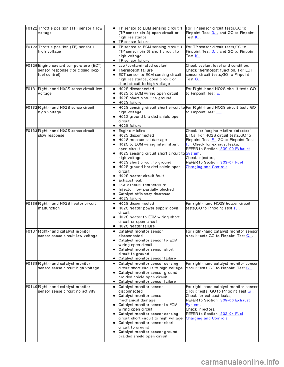
P0122Throttle
position (TP) sensor 1 low
voltage
TP se ns
or to ECM sensing circuit 1
(TP sensor pin 3) open circuit or
high resistance
TP sensor fail
ure
F
o
r TP sensor circ
uit tests,GO to
Pinpoint Test D.
, and GO
to Pinpoint
Test K.
.
P0123Throttl e
position (TP) sensor 1
high voltage
TP se ns
or to ECM sensing circuit 1
(TP sensor pin 3) short circuit to
high voltage
TP sensor fail
ure
F
o
r TP sensor circ
uit tests,GO to
Pinpoint Test D.
, and GO
to Pinpoint
Test K.
.
P0125En
gine coolant temperature (ECT)
sensor response (for closed loop
fuel control)
Low/contaminated coolant Therm o
stat failure
ECT se
ns
or to ECM sensing circuit
high resistance, open circuit or
short circuit to high voltage
Che c
k coolant level and condition.
Check thermostat function. For ECT
sensor circuit tests,GO to Pinpoint
Test C.
.
P0131Right -
hand H02S sense circuit low
voltage
H02 S
disconnected
H0
2S to
ECM wiring open circuit
H0
2S short ci
rcuit to ground
H0
2S fail
ure
F
or R
ight-hand HO2S circuit tests,GO
to Pinpoint Test E.
.
P0132Right-
hand H02S sense circuit
high voltage
H02 S
sensing circuit short circuit to
high voltage
H0 2S groun
d braided shield open
circuit
H0 2S fail
ure
F
or R
ight-hand HO2S circuit tests,GO
to Pinpoint Test E.
.
P0133Right-
hand H02S sense circuit
slow response
Engine m
isfire
H02
S
disconnected
H0
2S mechanical damage
H0
2S to
ECM wiring intermittent
open circuit
H02 S
sensing circuit short circuit to
high voltage
H02S short ci
rcuit to ground
H02S groun
d braided shield open
circuit
H0 2S heater circuit faul
t
Exhaus
t leak
Low e
x
haust temperature
Injector fl
ow parti
ally blocked
Catal
y
st efficiency decrease
H0
2S fail
ure
Chec
k for 'en
gine misfire detected'
DTCs. For HO2S circuit tests,GO to
Pinpoint Test E.
.G
O to Pinpoint Test
F.
. Check for exhaust leaks,
REF
ER to Section 309
-00
Ex
haust
Sy
ste
m
.
Chec k inje
ctors,
REFER to Section 303
-04 Fu
el
Charging and Cont
rols
.
P0135Right
-
hand H02S heater circuit
malfunction
H02 S
disconnected
H0
2S h
eater power supply open
circuit
H0 2S heater to ECM wi
ring short
circuit or open circuit
H0 2S heater fai
lure
F
o
r right-hand HO2S heater circuit
tests,GO to Pinpoint Test F.
.
P0137Right-
hand catalyst monitor
sensor sense circuit low voltage
Catal y
st monitor sensor
disconnected
Catal y
st monitor sensor to ECM
wiring open circuit
Catal y
st monitor sensor short
circuit to ground
Cat a
lyst monitor sensor failure
F
or ri
ght-hand catalyst monitor sensor
circuit tests,GO to Pinpoint Test G.
.
P0138Right -
hand catalyst monitor
sensor sense circuit high voltage
Catal y
st monitor sensor sensing
circuit short circuit to high voltage
Catalyst
monitor sensor ground
braided shield open circuit
Cata
lyst monitor sensor failure
F
or ri
ght-hand catalyst monitor sensor
circuit tests,GO to Pinpoint Test G.
.
P0140Right -
hand catalyst monitor
sensor sense circuit no activity
Catal y
st monitor sensor
disconnected
Catal y
st monitor sensor
mechanical damage
Catal y
st monitor sensor to ECM
wiring open circuit
Catal y
st monitor sensor sensing
circuit short circuit to high voltage
Cataly
st monitor sensor short
circuit to ground
Catalyst
monitor sensor ground
braided shield open circuit
F or ri
ght-hand catalyst monitor sensor
circuit tests, GO to Pinpoint Test G.
.
Check f o
r exhaust leaks,
REFER to Section 309
-00 Ex
haust
Sy
ste
m
.
Chec k inje
ctors,
REFER to Section 303
-04 Fu
el
Charging and Con
t
rols
.
Page 1197 of 2490
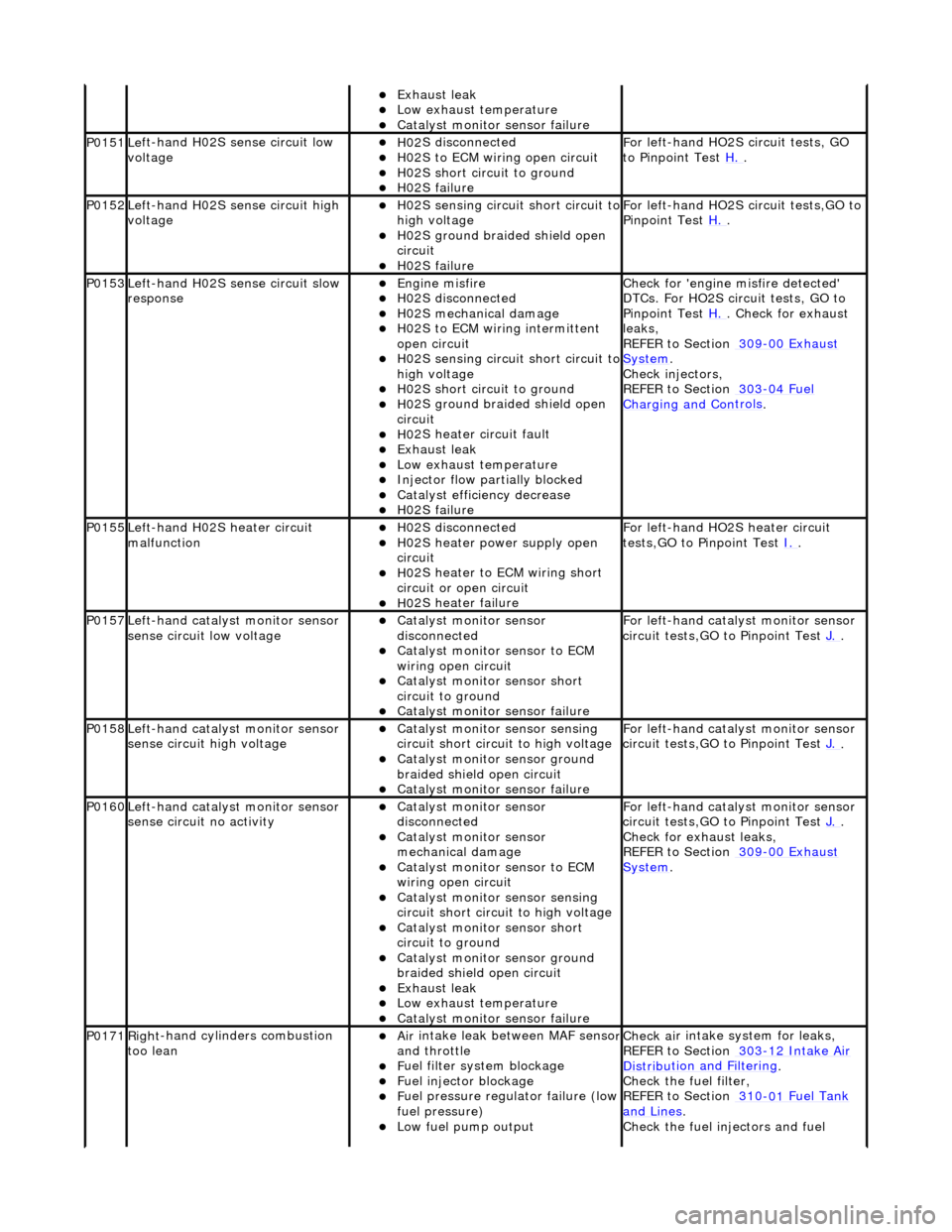
Exhaus
t leak
Low e
xhaust temperature
Cat
alyst monitor sensor failure
P0151Le
ft-hand H02S sense circuit low
voltage
H02
S disconnected
H0
2S to ECM wiring open circuit
H0
2S short circuit to ground
H0
2S failure
F
or left-hand HO2S circuit tests, GO
to Pinpoint Test H.
.
P0152Le
ft-hand H02S sense circuit high
voltage
H02
S sensing circuit short circuit to
high voltage
H0
2S ground braided shield open
circuit
H0
2S failure
F
or left-hand HO2S circuit tests,GO to
Pinpoint Test H.
.
P0153Le
ft-hand H02S sense circuit slow
response
Engine
misfire
H02
S disconnected
H0
2S mechanical damage
H0
2S to ECM wiring intermittent
open circuit
H02
S sensing circuit short circuit to
high voltage
H0
2S short circuit to ground
H0
2S ground braided shield open
circuit
H0
2S heater circuit fault
Exhaus
t leak
Low e
xhaust temperature
Injector fl
ow partially blocked
Catal
yst efficiency decrease
H0
2S failure
Chec
k for 'engine misfire detected'
DTCs. For HO2S circ uit tests, GO to
Pinpoint Test H.
. Check for exhaust
leak
s,
REFER to Section 309
-00
Exhaust
Sy
stem
.
Chec
k injectors,
REFER to Section 303
-04
Fuel
Charging and Con
trols
.
P0155Left-hand H02S heater
circuit
malfunction
H02
S disconnected
H0
2S heater power supply open
circuit
H0
2S heater to ECM wiring short
circuit or open circuit
H0
2S heater failure
F
or left-hand HO2S heater circuit
tests,GO to Pinpoint Test I.
.
P0157Le
ft-hand catalyst monitor sensor
sense circuit low voltage
Catal
yst monitor sensor
disconnected
Catal
yst monitor sensor to ECM
wiring open circuit
Catal
yst monitor sensor short
circuit to ground
Cat
alyst monitor sensor failure
F
or left-hand catalyst monitor sensor
circuit tests,GO to Pinpoint Test J.
.
P0158Le
ft-hand catalyst monitor sensor
sense circuit high voltage
Catal
yst monitor sensor sensing
circuit short circuit to high voltage
Catalyst
monitor sensor ground
braided shield open circuit
Cat
alyst monitor sensor failure
F
or left-hand catalyst monitor sensor
circuit tests,GO to Pinpoint Test J.
.
P0160Le
ft-hand catalyst monitor sensor
sense circuit no activity
Catal
yst monitor sensor
disconnected
Catal
yst monitor sensor
mechanical damage
Catal
yst monitor sensor to ECM
wiring open circuit
Catal
yst monitor sensor sensing
circuit short circuit to high voltage
Catal
yst monitor sensor short
circuit to ground
Catalyst
monitor sensor ground
braided shield open circuit
Exhaus
t leak
Low e
xhaust temperature
Cat
alyst monitor sensor failure
F
or left-hand catalyst monitor sensor
circuit tests,GO to Pinpoint Test J.
.
Check f
or exhaust leaks,
REFER to Section 309
-00
Exhaust
Sy
stem
.
P0171Right
-hand cylinders combustion
too lean
Air
intake leak between MAF senso
r and th
rottle
F
uel filter system blockage
F
uel injector blockage
F
uel pressure regulator failure (low
fuel pressure)
Low f
uel pump output
Check ai
r intake system for leaks,
REFER to Section 303
-1
2 Intake Air
Distribu
tion and Filtering
.
Check the fuel fi
lter,
REFER to Section 310
-01
Fuel Tank
and Lines.
Chec
k the fuel injectors and fuel
Page 1200 of 2490
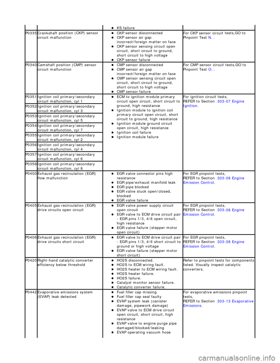
KS fail
ure
P0335Cranksh
a
ft positi
on (CKP) sensor
circuit malfunction
CK P
sensor disconnected
CKP sensor air gap
i
n
correct/foreign matter on face
CKP sensor sen
s
ing circuit open
circuit, short circuit to ground,
short circuit to high voltage
CKP s e
nsor failure
F
or CKP sensor circ ui
t tests,GO to
Pinpoint Test N.
.
P0340Camshaft position
(CMP) sensor
circuit malfunction
CM P
sensor disconnected
CMP sensor air gap
i
n
correct/foreign matter on face
CMP sensor sen
s
ing circuit open
circuit, short circuit to ground,
short circuit to high voltage
CMP s e
nsor failure
F
or CMP sensor circ ui
t tests,GO to
Pinpoint Test O.
.
P0351Igniti
on coil primary/secondary
circuit malfunction, cyl 1
ECM to ignit
ion module primary
circuit open circuit, short circuit to
ground, high resistance
Igniti
on module to ignition coil
primary circuit open circuit, short
circuit to ground, high resistance
Ignition modu le
ground circuit
open circuit, hi gh resistance
Ignition coil fail
ure
Ignition modul
e
failure
F
o
r ignition circuit tests,
REFER to Section 303
-07 En
gine
Ignition. P0352Ignit
i
on coil primary/secondary
circuit malfunction, cyl 3
P0353Ignit i
on coil primary/secondary
circuit malfunction, cyl 5
P0354Ignit i
on coil primary/secondary
circuit malfunction, cyl 7
P0355Ignit i
on coil primary/secondary
circuit malfunction, cyl 2
P0356Ignit i
on coil primary/secondary
circuit malfunction, cyl 4
P0357Ignit i
on coil primary/secondary
circuit malfunction, cyl 6
P0358Ignit i
on coil primary/secondary
circuit malfunction, cyl 8
P0400Exhaus t gas
recirculation (EGR)
flow malfunction
EGR valve c
onnector pins high
resistance
EGR pipe/exhaust manifol
d leak
EGR pipe blocke
d
EGR valve st
uck open/closed,
blocked
EGR valve fai
lure
For EGR
pinpoint t
ests,
REFER to Section 303
-08 En
gine
Emission Control.
P0405Exhaus
t gas
recirculation (EGR)
drive circuits open circuit
EGR valve power supply circuit
o p
en circuit
EGR valve t
o
ECM drive circuit pair
- EGR pins 1/3, 4/6 open circuit,
high resistance
EGR val v
e failure (stepper motor
open circuit)
For EGR pinpoint t
ests,
REFER to Section 303
-08 En
gine
Emissi
on Control.
P0406Exhaus t gas
recirculation (EGR)
drive circuits short circuit
EGR valve t o
ECM drive circuit pair
- EGR pins 1/3, 4/6 short circuit to
ground or high voltage
EGR val v
e failure (stepper motor
short circuit)
For EGR pinpoint t
ests,
REFER to Section 303
-08 En
gine
Emissi
on Control.
P0420Right-
hand catalytic converter
efficiency below threshold
HO2S di
sconnected.
HO2
S
to ECM wiring fault.
HO2
S
heater to ECM wiring fault.
HO2
S
heater failure.
HO2
S
failure.
Cat
a
lyst monitor sensor failure.
Catal
y
tic converter failure.
R
e
fer to pinpoint tests for components
listed. Visually inspect catalytic
converters.
P0442Evaporati v
e emissions system
(EVAP) leak detected
Fue l
filler cap missing
Fu
el filler cap seal faulty
EVAP system
leak (can
ister
damage, pipework damage)
EVAP v a
lve to ECM drive circuit
open circuit, short circuit, high
resistance
EVAP valve to engine pu rge pipe
damaged/blocked/leaking
EVAP ope r
ating vacuum hose
F
or evaporati
ve emissions pinpoint
tests,
REFER to Section 303
-1 3
Evaporative
Emissi
ons
.
Page 1211 of 2490
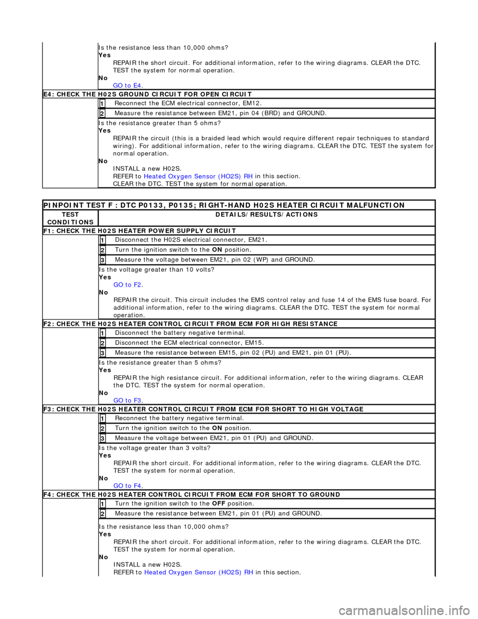
Is
the resistance less than 10,000 ohms?
Yes REPAIR the short circuit. For addi tional information, refer to the wiring diagrams. CLEAR the DTC.
TEST the system for normal operation.
No GO to E4
.
E4
: CHECK THE H02S GROUND
CIRCUIT FOR OPEN CIRCUIT
Re
connect the ECM electrical connector, EM12.
1
Meas
ure the resistance between EM21, pin 04 (BRD) and GROUND.
2
Is th
e resistance greater than 5 ohms?
Yes
REPAIR the circuit (this is a braide d lead which would require different repair techniques to standard
wiring). For additional information, refer to the wiring diagrams. CL EAR the DTC. TEST the system for
normal operation.
No INSTALL a new H02S.
REFER to Heated Oxygen Sensor (HO2S) RH
in this section.
CLEAR the DTC. TEST the syst em for normal operation.
PI
NPOINT TEST F : DTC P0133, P0135; RIGHT-HAND H02S HEATER CIRCUIT MALFUNCTION
TE
ST
CONDITIONS
D
ETAILS/RESULTS/ACTIONS
F1:
CHECK THE H02S HEATER POWER SUPPLY CIRCUIT
D
isconnect the H02S electrical connector, EM21.
1
Turn the ignition swi
tch to the ON
position.
2
Meas
ure the voltage between EM21, pin 02 (WP) and GROUND.
3
Is the vol
tage greater than 10 volts?
Yes GO to F2
.
No
REPAIR the circuit. This circuit in cludes the EMS control relay and fu se 14 of the EMS fuse board. For
additional information, refer to the wiring diagrams. CLEAR the DT C. TEST the system for normal
operation.
F2: CHECK THE H02
S HEATER CONTROL CI
RCUIT FROM ECM FOR HIGH RESISTANCE
Di
sconnect the battery negative terminal.
1
D
isconnect the ECM electrical connector, EM15.
2
Me
asure the resistance between EM15, pin 02 (PU) and EM21, pin 01 (PU).
3
Is th
e resistance greater than 5 ohms?
Yes REPAIR the high resistance circui t. For additional information, refer to the wiring diagrams. CLEAR
the DTC. TEST the system for normal operation.
No GO to F3
.
F3: CHECK THE H02
S HEATER CONTROL CIRCUI
T FROM ECM FOR SHORT TO HIGH VOLTAGE
R
econnect the battery negative terminal.
1
Turn the ignition swi
tch to the ON
position.
2
Meas
ure the voltage between EM21, pin 01 (PU) and GROUND.
3
Is th
e voltage greater than 3 volts?
Yes REPAIR the short circuit. For addi tional information, refer to the wiring diagrams. CLEAR the DTC.
TEST the system for normal operation.
No GO to F4
.
F4: CHECK THE H02
S HEATER CONTROL CI
RCUIT FROM ECM FOR SHORT TO GROUND
Turn the ignition swi
tch to the OFF
position.
1
Meas
ure the resistance between EM21, pin 01 (PU) and GROUND.
2
Is
the resistance less than 10,000 ohms?
Yes REPAIR the short circuit. For addi tional information, refer to the wiring diagrams. CLEAR the DTC.
TEST the system for normal operation.
No INSTALL a new H02S.
REFER to Heated Oxygen Sensor (HO2S) RH
in this section.
Page 1213 of 2490
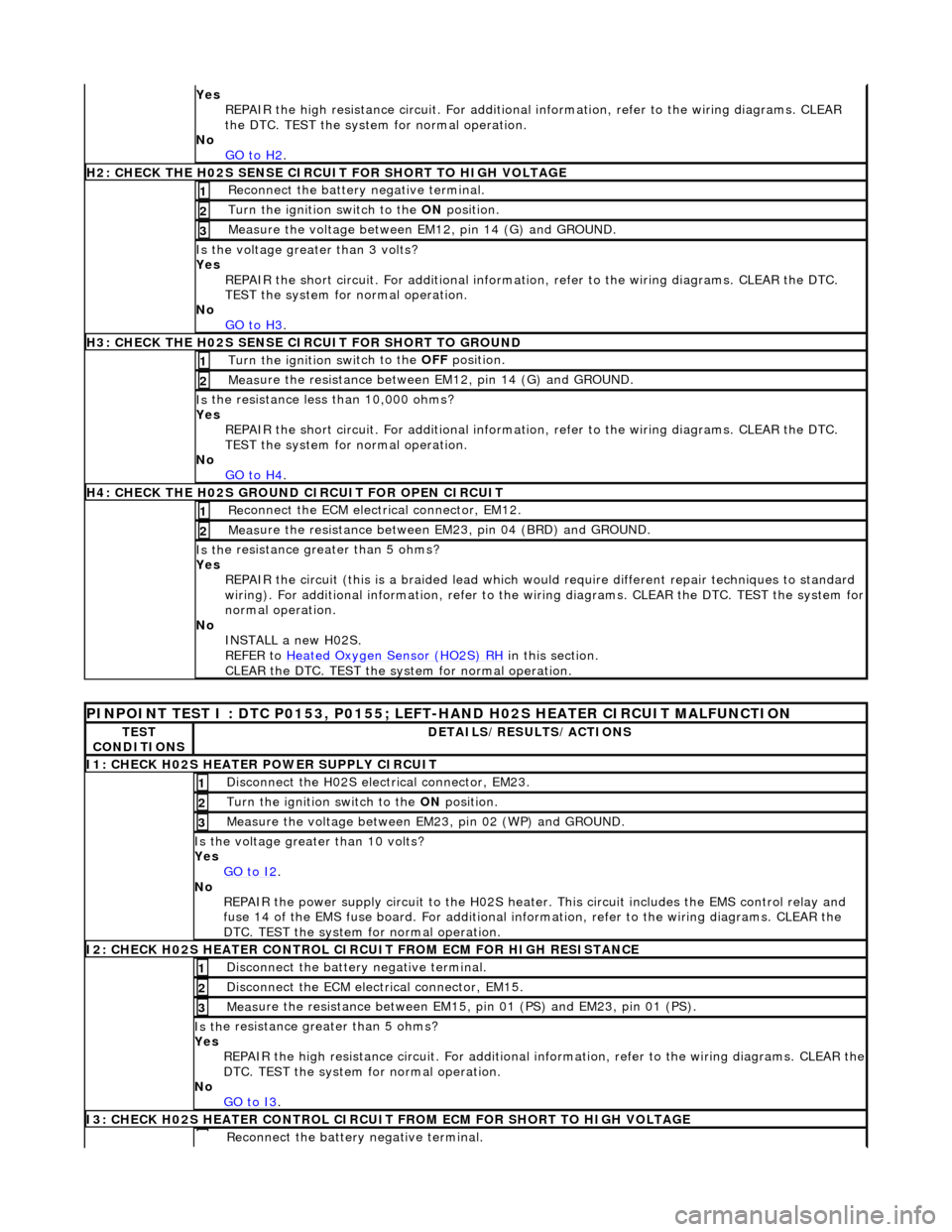
Yes
REPAIR the high resistance circui t. For additional information, refer to the wiring diagrams. CLEAR
the DTC. TEST the system for normal operation.
No GO to H2
.
H
2: CHECK THE H02S SENSE CIRCUIT FOR SHORT TO HIGH VOLTAGE
R
econnect the battery negative terminal.
1
Turn the ignition swi
tch to the ON
position.
2
M
easure the voltage between EM12, pin 14 (G) and GROUND.
3
Is th
e voltage greater than 3 volts?
Yes REPAIR the short circuit. For addi tional information, refer to the wiring diagrams. CLEAR the DTC.
TEST the system for normal operation.
No GO to H3
.
H
3: CHECK THE H02S SENSE CIRCUIT FOR SHORT TO GROUND
Turn the ignition swi
tch to the OFF
position.
1
Meas
ure the resistance between EM12, pin 14 (G) and GROUND.
2
Is
the resistance less than 10,000 ohms?
Yes REPAIR the short circuit. For addi tional information, refer to the wiring diagrams. CLEAR the DTC.
TEST the system for normal operation.
No GO to H4
.
H4:
CHECK THE H02S GROUND CIRCUIT FOR OPEN CIRCUIT
Re
connect the ECM electrical connector, EM12.
1
Meas
ure the resistance between EM23, pin 04 (BRD) and GROUND.
2
Is th
e resistance greater than 5 ohms?
Yes REPAIR the circuit (this is a braide d lead which would require different repair techniques to standard
wiring). For additional information, refer to the wiring diagrams. CL EAR the DTC. TEST the system for
normal operation.
No INSTALL a new H02S.
REFER to Heated Oxygen Sensor (HO2S) RH
in this section.
CLEAR the DTC. TEST the syst em for normal operation.
P
INPOINT TEST I : DTC P0153, P0155; LEFT-HAND H02S HEATER CIRCUIT MALFUNCTION
TE
ST
CONDITIONS
D
ETAILS/RESULTS/ACTIONS
I
1: CHECK H02S HEATER POWER SUPPLY CIRCUIT
D
isconnect the H02S electrical connector, EM23.
1
Turn the ignition swi
tch to the
ON position.
2
Meas
ure the voltage between EM23, pin 02 (WP) and GROUND.
3
Is the vol
tage greater than 10 volts?
Yes GO to I2
.
No
REPAIR the power supply circuit to the H02S heater. This circuit includes the EMS control relay and
fuse 14 of the EMS fuse board. For additional info rmation, refer to the wiring diagrams. CLEAR the
DTC. TEST the system for normal operation.
I
2: CHECK H02S HEATER CONTROL CIRC
UIT FROM ECM FOR HIGH RESISTANCE
Di
sconnect the battery negative terminal.
1
D
isconnect the ECM electrical connector, EM15.
2
Meas
ure the resistance between EM15,
pin 01 (PS) and EM23, pin 01 (PS).
3
Is th
e resistance greater than 5 ohms?
Yes REPAIR the high resistance circuit. For additional information, refer to the wiring diagrams. CLEAR the
DTC. TEST the system for normal operation.
No GO to I3
.
I
3: CHECK H02S HEATER CONTROL CIRCUIT
FROM ECM FOR SHORT TO HIGH VOLTAGE
R
econnect the battery negative terminal.