Page 640 of 2490

2. In
stall the access grommet to the housing.
36. Lower the ramp.
37. Ins
tall and tighten the nuts which secure the exhaust manifold to the
downpipe catalyst.
38 . In
stall new seals to the A-Bank VVT bush carrier.
1. Install the new sealing ring (scarf jointed) to the carrier bush groove.
2. Install a new O-ring to the carrier oil-way.
39 . Install the bush c
arrier to the cylinder block.
Lu
br
icate the seal (scarf
jointed) and the bush.
1. Install the bush carrier assembly.
Chec k that
the seals are
in place and that the ri ng dowels are engaged
squarely. Fully locate the assembly as much as possible by hand
pressure.
2. Install the three securing bolts. Tighten to 21 Nm.
40. Install new sealing rings to the coolant outlet pipe grooves.
41. Install the coolant
outlet pipe.
1. Install the outlet pipe to the bypass hose and to the cylinder heads.
2. Install the four bolts which secure the outlet pipe.
42. Connect the hoses and multi-plug to the coolant outlet pipe.
1. Connect the heater hose and reposition the hose clip.
Page 907 of 2490

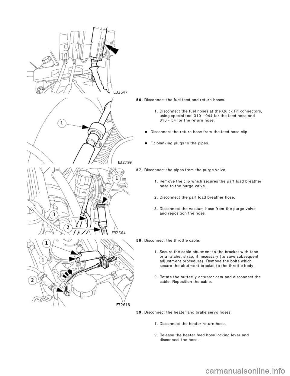
56. Disconnect the fuel feed and return hoses.
1. Disconnect the fuel hoses at the Quick Fit connectors,
using special tool 310 - 044 for the feed hose and
310 - 54 for the return hose.
Disconnect the return hose from the feed hose clip.
Fit blanking plugs to the pipes.
57. Disconnect the pipes from the purge valve.
1. Remove the clip which secu res the part load breather
hose to the purge valve.
2. Disconnect the part load breather hose.
3. Disconnect the vacuum hose from the purge valve and reposition the hose.
58. Disconnect the throttle cable.
1. Secure the cable abutment to the bracket with tape or a ratchet strap, if nece ssary (to save subsequent
adjustment procedure). Remove the bolts which
secure the abutment bracke t to the throttle body.
2. Rotate the butterfly actuator cam and disconnect the cable. Reposition the cable.
59. Disconnect the heater and brake servo hoses.
1. Disconnect the he ater return hose.
2. Release the heater feed hose locking lever and
disconnect the hose.
Page 915 of 2490
Connect
the front muffler to
the intermediate muffler,
noting the alignment of the indicator rings.
W
ith the front muffler positioned correctly, tighten the
clamps (left-hand and right-hand sides) to the catalytic
converter.
21
.
Tighten the clamps (left-hand and right-hand sides),
intermediate mufflers to front muffler.
22
.
Tighten the downpipe bracket se curing bolts to the correct
torque
23
.
Connect the oil cooler pipes (w here fitted) to the engine.
1. Remove the blanking plugs from the pipes and from the mating unions on the engine.
2. Fit new O-ring seals to the pipes and lubricate with new engine oil.
3. Connect the pipes to the engine and fit the clamping
plate and bolt.
24. Lower the vehicle on the ramp.
25. Connect the heater and brake servo hoses.
1. Connect the heat er return hose.
2. Connect the heater feed hose and secure the locking
lever.
Page 925 of 2490

T
he cooling system for the supercharged engine is very similar
to the normally aspirated engine, but with the addition of a
water cooled, intake air charge cooling system. This comprises a radiator, an electrically operated water pump and two
charge air cooler assemblies (heat exchangers) - one for each bank. The system works independently, but is connected to the
main cooling system at the bottom hose to allow for therma l expansion and to help to prevent unwanted circulation.
The condenser for the air conditioning system fits between th e coolant main radiator and the charge air cooling system
radiator.
Cylinder Block Heater, Drain Location
ItemDe
scription
1Rad
iator - Intake Air Coolant
2Ele
ctrically Operated Coolant Pump
3Top Hose
4Charge Air Coo
lers -
Intake Air Cooling
5Fi
lling Point for Intake Air Cooling
6N
on-Return Valves - Heater
7Ele
ctrically Operated Coolant Pump
8Hea
ter Matrix
9Wate
r Valve - Heater Control
10EGR V
alve (when fitted)
11Thr
ottle Body
12Coolan
t Recovery Bottle
13H
eader/Expansion Tank
14Eng
ine Coolant Pump
15The
rmostat Housing
16Bottom
Hose
17Air Bleed
Pipes
18Rad
iator - Main Cooling System
Page 926 of 2490
A coola n
t drain plug is located at the rear of the cylinder block.
Coolant may be drained from the A-bank, by removing the coolant pipe from behind the starter motor.
For vehicles fitted with the cold climate package, a cylinder block heater (shown) replaces the drain plug located on the B-
bank.
Coolant Pump and Flow Control
The coolant pump is fitted between the two cylinder banks, on the front face of the cylinder block.
The pump consists of a housing containing a shaft, with a sh rouded plastic impeller on one end and a drive pulley on the
other.
A pair of roller bearings support the shaft in the housing. A seal behind the impeller prevents coolant from contaminating the
bearings. Should this seal fail, coolant escapes from a witness hole in the housin g indicating that immediate action is
required.
An O-ring and an aluminum-alloy gasket, seal the ports between the pump and the cylinder banks.
Coolant Outlet Duct
Page 927 of 2490

A coola
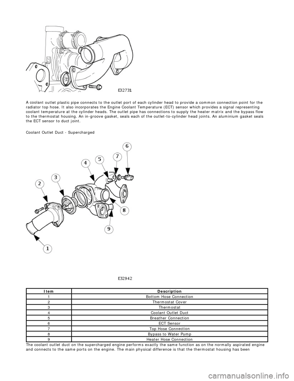
nt outlet plastic pipe connects to the outlet port of ea
ch cylinder head to provide a common connection point for the
radiator top hose. It also incorporates the Engine Coolant Te mperature (ECT) sensor which provides a signal representing
coolant temperature at the cylinder heads. The outlet pipe has connections to supply the heater matrix and the bypass flow
to the thermostat housing. An in-groove ga sket, seals each of the outlet-to-cylinder head joints. An aluminium gasket seals
the ECT sensor to duct joint.
Coolant Outlet Duct - Supercharged
The coolant outlet duct on the supercharged engine performs exactly the same function as on the normally aspirated engine
and connects to the same ports on the engine. The main physical difference is that the thermostat housing has been
ItemDe
scription
1Bottom
Hose Connection
2The
rmostat Cover
3The
rmostat
4Coolan
t Outlet Duct
5B
reather Connection
6ECT Se
nsor
7Top Hose Conn
ection
8Bypa
ss to Water Pump
9Hea
ter Hose Connection
Page 930 of 2490

Whe r
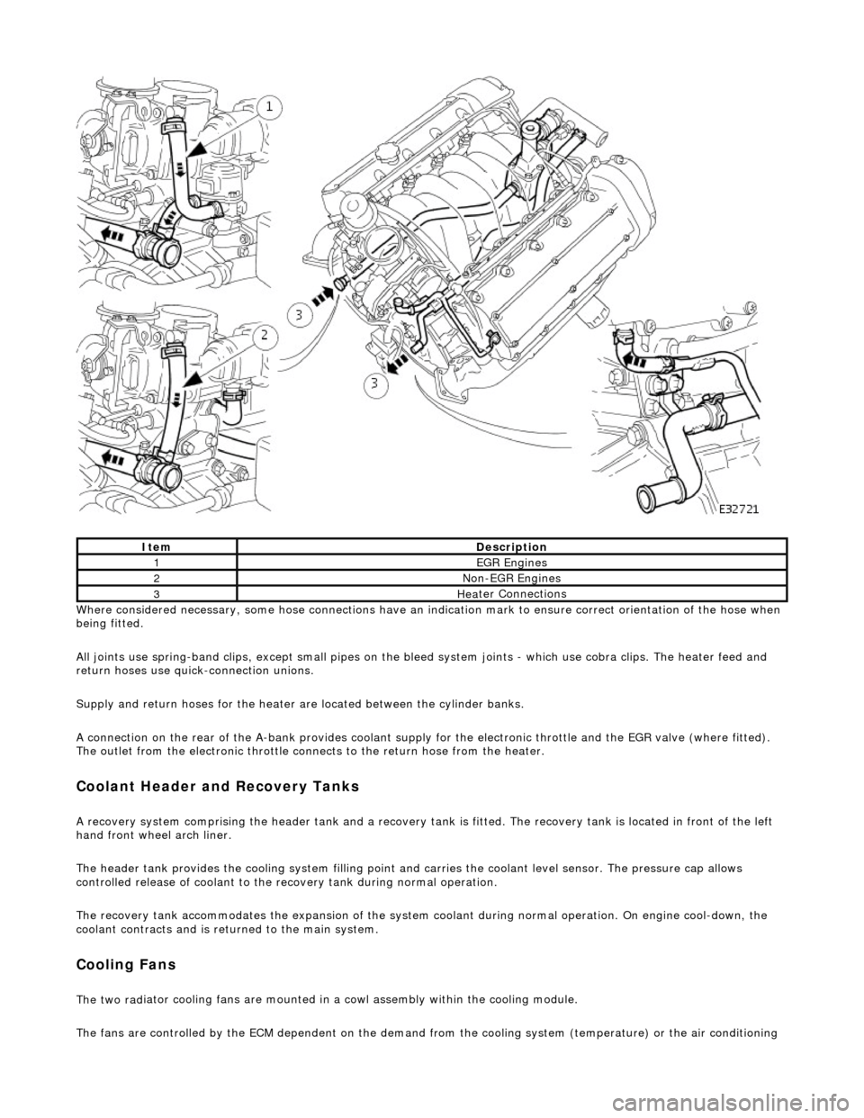
e considered necessary, some hose conn
ections have an indication mark to ensure correct orientation of the hose when
being fitted.
All joints use spring-band clips, except small pipes on the bleed system joints - which use cobra clips. The heater feed and
return hoses use quick-connection unions.
Supply and return hoses for the heater are located between the cylinder banks.
A connection on the rear of the A-bank provides coolant supply for the electronic throttle and the EGR valve (where fitted).
The outlet from the electronic throttle connects to the return hose from the heater.
Cool
ant Header and Recovery Tanks
A recovery system comp
rising the header tank
and a recovery tank is fitted. The recove ry tank is located in front of the left
hand front wheel arch liner.
The header tank provides the cooling system filling point and carries the coolant level sensor. The pressure cap allows
controlled release of coolant to the re covery tank during normal operation.
The recovery tank accommodates the expansion of the system coolant during normal operation. On engine cool-down, the
coolant contracts and is returned to the main system.
Coo lin
g Fans
The two
rad
iator cooling fans are mounted in
a cowl assembly within the cooling module.
The fans are controlled by the ECM dependent on the demand fr om the cooling system (temperature) or the air conditioning
ItemDescrip
tion
1EGR
E
ngines
2Non
-
EGR Engines
3Hea
ter Connections
Page 957 of 2490
9.
R
un the engine at between 1500 and 2000 rpm until the
cooling fans operate.
10. Switch on the climate control system, set to maximum heat,
and check that heat is coming from the heater at the fascia
vents or the footwell outlets.
11. Switch off the engine and allow it to cool down.
12. When cool, remove the pressure cap and top up the system
as necessary at the header tank.
13
.
If necessary, fit new seals to the pressure cap.
1. Remove both O-rings from the pressure cap.
Fit and
fully seat new O-rings
to the pressure cap. Fit the
pressure cap.
14. Check that the pressure cap is fitted. Remove the plug from
the air charge cooler fill point. Pour coolant carefully into the air
charge cooler fill point until the system is full.
F
it the plug to the fill poin
t, using a new Dowty sealing
washer.
15. Remove the paintwork protection sheets and close the engine
cover.