Page 875 of 2490

Engine - Valve Springs LH
In-vehicle Repair
Removal
Special Tool(s)
Valve spring compressor
303-252 1. Open the engine compartment and fit paintwork protection
sheets.
2. Set the engine compartment cover to the service access
position.
3. Disconnect the batt ery ground cable.
Remove the battery cover.
4. Remove the Timing Co ver. Refer to Operation 12.65.01 in this
Section. This operation includes draining the coolant from the
radiator and removing the cam covers.
5. Remove the Inlet Manifold. Refer to Operation 30.15.01 in this
Section. This operation includes depressurising the fuel system
and removing the throttle housing.
6. Remove the Cylinder Head an d Gasket. Refer to Operation
12.29.02 in this Section.
7. Remove the valve collets from the first valve.
1. Fit the valve spring compressor 303 - 252 to the relevant spring.
2. Compress the spring and remove the collets.
8. Remove the valve spring.
Remove the valve spring compressor 303 - 252.
1. Remove the valve collar.
2. Remove the valve spring.
Page 876 of 2490

Installation
9. Repeat the instructions for each valve spring to be removed.
10. Clean all relevant components.
1. Fit the valve spring.
1. Fit the valve spring.
2. Locate the valve collar onto the spring.
2. Refit the valve collets to the first valve.
1. Fit the valve spring compressor 303 - 252 to the relevant spring.
2. Compress the spring and fit the collets.
Remove the valve spring compressor and check that the
collets are correctly seated.
3. Repeat the instructions for each valve spring to be fitted.
4. Refit the Cylinder Head and Gasket. Refer to Operation
12.29.03 in this Section.
5. Refit the Inlet Manifold. Refer to Operation 30.15.01 in this
Section. This operation includes refitting the throttle housing.
6. Refit the Timing Cover. Refer to Operation 12.65.01 in this
Section. This operation includes refitting the cam covers and
refilling the coolant system.
7. Move the engine compartment co ver from the service position
and connect the gas struts.
8. Remove the paint protection sheets and close the cover.
9. Connect the battery and fit the battery cover.
Refer to the Battery Reconnection Procedure 86.15.15.
Page 877 of 2490

Engine - Valve Springs RH
In-vehicle Repair
Removal
Special Tool(s)
Valve spring compressor
303-252 1. Open the engine compartment and fit paintwork protection
sheets.
2. Set the engine compartment cover to the service access
position.
3. Disconnect the batt ery ground cable.
Remove the battery cover.
4. Remove the Timing Co ver. Refer to Operation 12.65.01 in this
Section. This operation includes draining the coolant from the
radiator and removing the cam covers.
5. Remove the Inlet Manifold. Refer to Operation 30.15.01 in this
Section. This operation includes depressurising the fuel system
and removing the throttle housing.
6. Remove the Cylinder Head an d Gasket. Refer to Operation
12.29.03 in this Section.
7. Remove the valve collets from the first valve.
1. Fit the valve spring compressor 303 - 252 to the relevant spring.
2. Compress the spring and remove the collets.
8. Remove the valve spring.
Remove the valve spring compressor 303 - 252.
1. Remove the valve collar.
2. Remove the valve spring.
Page 878 of 2490
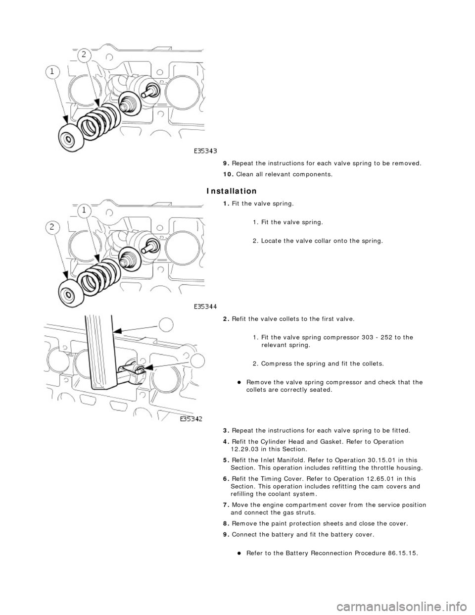
Installation
9. Repeat the instructions for each valve spring to be removed.
10. Clean all relevant components.
1. Fit the valve spring.
1. Fit the valve spring.
2. Locate the valve collar onto the spring.
2. Refit the valve collets to the first valve.
1. Fit the valve spring compressor 303 - 252 to the relevant spring.
2. Compress the spring and fit the collets.
Remove the valve spring compressor and check that the
collets are correctly seated.
3. Repeat the instructions for each valve spring to be fitted.
4. Refit the Cylinder Head and Gasket. Refer to Operation
12.29.03 in this Section.
5. Refit the Inlet Manifold. Refer to Operation 30.15.01 in this
Section. This operation includes refitting the throttle housing.
6. Refit the Timing Cover. Refer to Operation 12.65.01 in this
Section. This operation includes refitting the cam covers and
refilling the coolant system.
7. Move the engine compartment co ver from the service position
and connect the gas struts.
8. Remove the paint protection sheets and close the cover.
9. Connect the battery and fit the battery cover.
Refer to the Battery Reconnection Procedure 86.15.15.
Page 927 of 2490
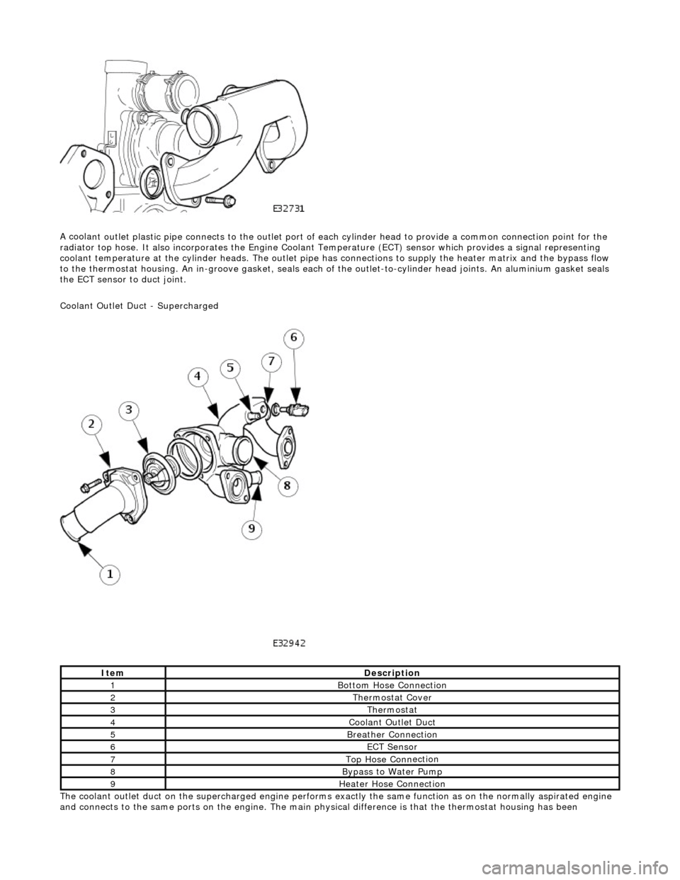
A coola
nt outlet plastic pipe connects to the outlet port of ea
ch cylinder head to provide a common connection point for the
radiator top hose. It also incorporates the Engine Coolant Te mperature (ECT) sensor which provides a signal representing
coolant temperature at the cylinder heads. The outlet pipe has connections to supply the heater matrix and the bypass flow
to the thermostat housing. An in-groove ga sket, seals each of the outlet-to-cylinder head joints. An aluminium gasket seals
the ECT sensor to duct joint.
Coolant Outlet Duct - Supercharged
The coolant outlet duct on the supercharged engine performs exactly the same function as on the normally aspirated engine
and connects to the same ports on the engine. The main physical difference is that the thermostat housing has been
ItemDe
scription
1Bottom
Hose Connection
2The
rmostat Cover
3The
rmostat
4Coolan
t Outlet Duct
5B
reather Connection
6ECT Se
nsor
7Top Hose Conn
ection
8Bypa
ss to Water Pump
9Hea
ter Hose Connection
Page 1040 of 2490
Fuel Char
ging and Controls - Fu
el Injectors4.0L SC V8 - AJ26
Remo
val and Installation
Remov
a
l
Installation
1. Disc onne
ct battery ground cable (IMPORTANT, see SRO
86.15.19 for further information).
2. WARNING: BEFORE PROCEEDING, IT IS ESSENTIAL THAT
THE WARNING NOTES GIVEN IN SECTION 100-00 (UNDER THE
HEADING 'SAFETY PRECAUTIONS') ARE READ AND
UNDERSTOOD.
Depressurize fuel syst em; refer to 19.50.02.
3. Drain radiator coolant; refer to 2
6.10.01.
4. Remove air cleaner cover / inta ke assembly; refer 19.10.30.
5. Remove throttle body; refer to 19.70.04.
6. Remove throttle induction elbo w; refer to (SC) 19.70.28.
7. Remove exhaust gas re-circulation valve (EGR) if fitted; refer
to 17.45.01.
8. Remove supercharger outlet duct and gasket; refer to
18.50.16.
9. Remove coolant outlet pipe; refer to (SC) 26.31.08 .
10. Remove supercharger drive belt; refer to 18.50.08.
11. Remove supercharger assembly; refer to 18.50.15.
12. Remove bank 1 or 2 charge air cooler as required; refer to
18.50.18 and / or 18.50.19.
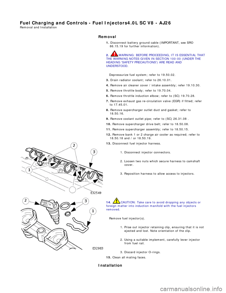
13 . Di
sconnect fuel injector harness.
1. Disconnect injector connectors.
2. Loosen two nuts which se cure harness to camshaft
cover.
3. Reposition harness to al low access to injectors.
14. CAUTI
ON: Take care to avoi
d dropping any objects or
foreign matter into induction ma nifold with the fuel injectors
removed.
Remove fuel injector(s). 1. Prise out injector retaining clip, ensuring that it is not
ejected and lost. Note orientation of the clip.
2. Using a suitable implemen t, carefully lever injector
from fuel rail.
3. Discard injector O-rings.
15 . Cle
an all mating faces.
Page 1111 of 2490
the
intake elbow provide connections for vacuum actuators and are also used to redirect emissions into the engine.
On the right-hand side of the elbow a la rge diameter pipe connects to the brake servo. The smaller pipe provides a vacuum
feed to the fuel rail pressure regulator and throttle cruise control system. On the le ft-hand side of the elbow the front pipe
supplies vacuum control for the evaporative emissions system valves.
Emissions from the engine part load breather (bank 2) and pu rged fuel vapor from the EVAP valve are drawn via a common
T piece into the left-hand side of the intake elbow. Re-cir culated exhaust gas enters the intake elbow via the EGR valve
which is mounted directly on the rear of the elbow : where the EGR system is not used, a blanking plate is fitted.
The fuel system, throttle and emission control system s are described more fully in the relevant sections.
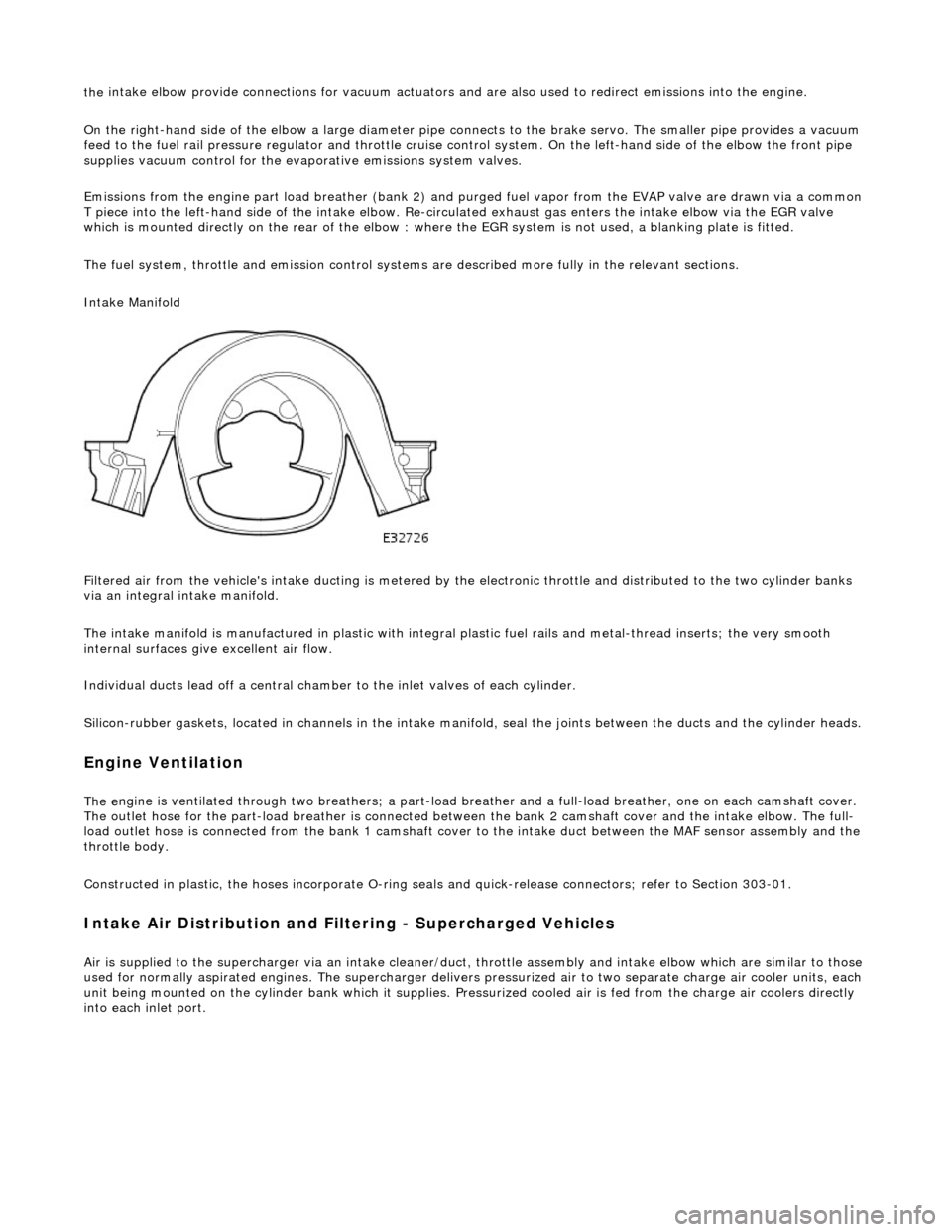
Intake Manifold
Filtered air from the vehicle's intake ducting is metered by th e electronic throttle and distributed to the two cylinder banks
via an integral intake manifold.
The intake manifold is manufactured in plastic with integral plastic fuel rails and metal-thread inserts; the very smooth
internal surfaces give excellent air flow.
Individual ducts lead off a central chamber to the inlet valves of each cylinder.
Silicon-rubber gaskets, loca ted in channels in the intake manifold, seal th e joints between the ducts and the cylinder heads.
Engine Ventilation
The e
ngine is ventilated through two brea
thers; a part-load breather and a full-load breather, one on each camshaft cover.
The outlet hose for the part-load breather is connected between the bank 2 camshaft cover and the intake elbow. The full-
load outlet hose is connected from the bank 1 camshaft cover to the intake duct between the MAF sensor assembly and the
throttle body.
Constructed in plastic, the hoses incorporate O-ring seal s and quick-release connectors; refer to Section 303-01.
I
ntake Air Distribution and Filtering - Supercharged Vehicles
Ai
r is supplied to the supercharger via an
intake cleaner/duct, throttle assembly and intake elbow which are similar to those
used for normally aspirated engines. The su percharger delivers pressurized air to two separate charge air cooler units, each
unit being mounted on the cy linder bank which it supplies. Pr essurized cooled air is fed from the charge air coolers directly
into each inlet port.
Page 1134 of 2490
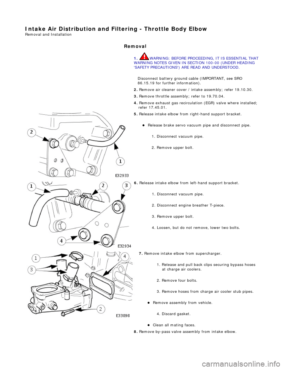
Intake Air Distribution and Filtering - Thrott
le Body Elbow
Re
mo
val and Installation
Remov
a
l
1.
WARNING: B E
FORE PROCEEDING, IT IS ESSENTIAL THAT
WARNING NOTES GIVEN IN SECTION 100-00 (UNDER HEADING
'SAFETY PRECAUTIONS') AR E READ AND UNDERSTOOD.
Disconnect battery ground cable (IMPORTANT, see SRO
86.15.19 for further information).
2. Re
move air cleaner cover / inta
ke assembly; refer 19.10.30.
3. Remove throttle assemb ly; refer to 19.70.04.
4. Remove exhaust gas recirculation (EGR) valve where installed;
refer 17.45.01.
5. Re
lease intake elbow from right-hand support bracket.
Re
lea
se brake servo vacuum pi
pe and disconnect pipe.
1. Disconnect vacuum pipe.
2. Remove upper bolt.
6. Relea
se intake elbow from le
ft-hand support bracket.
1. Disconnect vacuum pipe.
2. Disconnect engine breather T-piece.
3. Remove upper bolt.
4. Loosen, but do not remove, lower two bolts.
7. Re
move intake elbow from supercharger.
1. Release and pull back cl ips securing bypass hoses
at charge air coolers.
2. Remove four bolts.
3. Remove hoses from charge air cooler stub pipes.
Re move as
sembly from vehicle.
4. Discard gasket.
Cle a
n all mating faces.
8. Remove by-pass valve assembly from intake elbow.