Page 1876 of 2490

Battery, Mounting and Cables - Battery and Cables Description and Operation
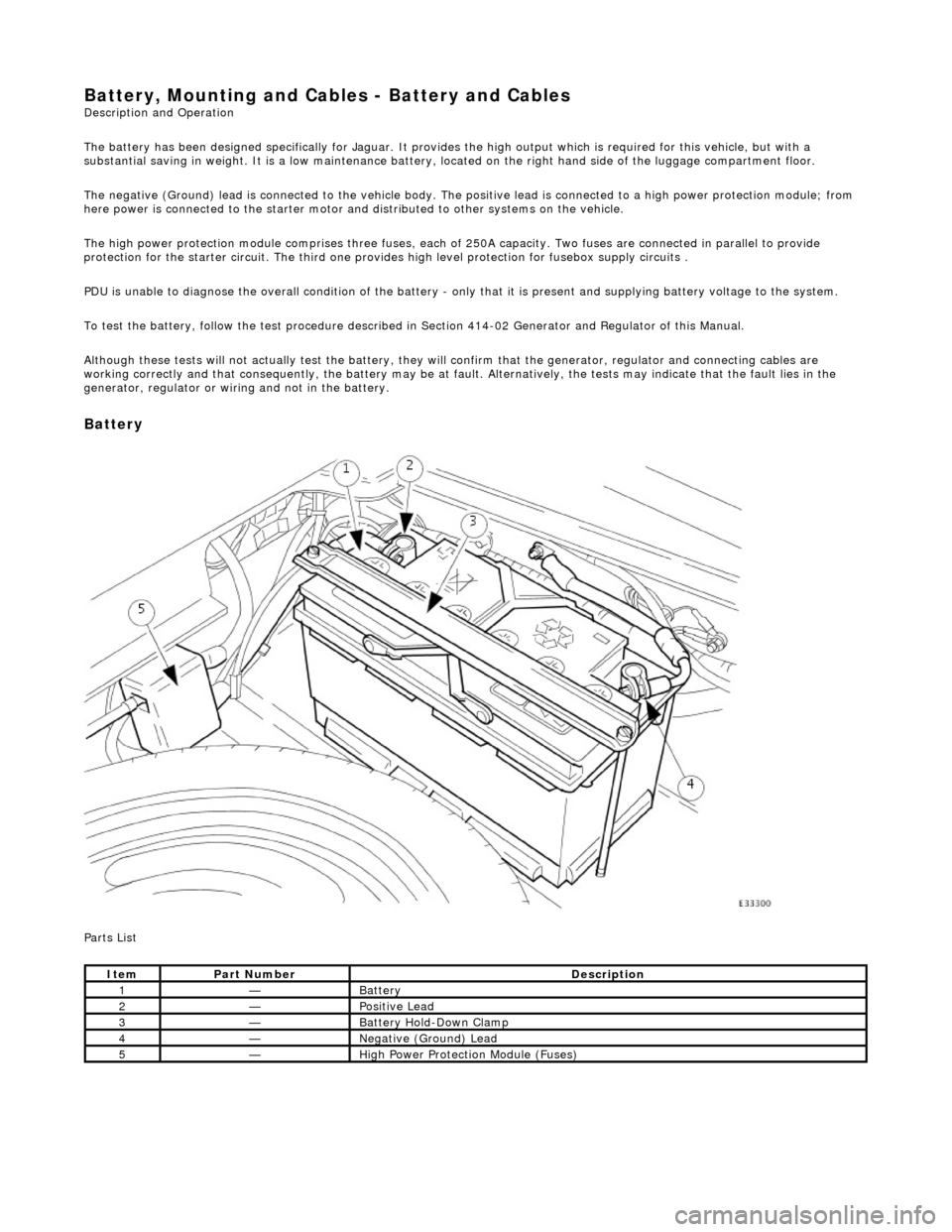
The battery has been designed specifically for Jaguar. It provides the high output which is required for this vehicle, but with a
substantial saving in weight. It is a low maintenance battery, located on the right ha nd side of the luggage compartment floor.
The negative (Ground) lead is connected to the vehicle body. The positive lead is connected to a high power protection module; from
here power is connected to the starter motor an d distributed to other systems on the vehicle.
The high power protection module comprises three fuses, each of 250A capacity. Two fuses are connected in parallel to provide
protection for the starter circuit. Th e third one provides high level protection for fusebox supply circuits .
PDU is unable to diagnose the overall condition of the battery - only that it is present and supplying battery voltage to the system.
To test the battery, follow the test procedure described in Section 414-02 Generator and Regulator of this Manual.
Although these tests will not actually test the battery, they will confirm that the generator, regulator and connecting cables are
working correctly and that conseq uently, the battery may be at fault. Alternatively, the tests may indicate that the fault lies in the
generator, regulator or wiring and not in the battery.
Battery
Parts List
ItemPart NumberDescription
1—Battery
2—Positive Lead
3—Battery Hold-Down Clamp
4—Negative (Ground) Lead
5—High Power Protection Module (Fuses)
Page 1877 of 2490
Battery, Mounting and Cables - Battery Connect
General Procedures
1.
NOTE: Whether one, or both, cables are disconnected, a
minimum of 30 seconds MUST elapse between disconnection of
the FIRST cable and reconnection of the LAST cable. A clean final
connection must be made; do not allow temporary contact.
Connect the batter y terminal(s).
2. Reset the clock.
3. Enter the radio security code. If necessary, refer to the Sound
System Handbook.
Page 1878 of 2490
Battery, Mounting and Cables - Battery
Removal and Installation
Removal
Installation
1.
Remove the luggage compartment floor panel (when standard
size spare wheel is supplied) and the cover from the battery.
2. Disconnect the battery cables.
Disconnect the ground cable. Disconnect the positive cable.
1. Disconnect the vent pipe.
3. Remove the battery.
1. Remove the two bolts which secure the battery clamp.
2. Remove the clamp.
3. Remove the battery.
1. Installation is the reverse of removal.
2. Perform the Battery Reconnection Procedure described in this
section.
Page 1879 of 2490
Battery, Mounting and Cables - Battery Ground Cable
Removal and Installation
Removal
Installation
1.
Remove the luggage compartment floor panel (when standard
size spare wheel is supplied) and the cover from the battery.
2. Remove the negative lead.
Reposition the front e dge of the side trim for access to the
ground stud.
1. Slacken the clamp of the ne gative lead at the battery
terminal. Disconnect the negative lead from the
battery terminal.
2. Remove the nut from the ground stud.
3. Remove the negative lead.
1. Installation is the reverse of removal.
2. Perform the Battery Reconnection Procedure described in this
section.
Page 1880 of 2490
Battery, Mounting and Cables - Battery Positive Cable
Removal and Installation
Removal
Installation
1.
Remove the luggage compartment floor panel (when standard
size spare wheel is supplied) and the cover from the battery.
2. Disconnect the positive lead.
1. Slacken the clamp of the po sitive lead at the battery
terminal. Disconnect the positive lead from the
battery terminal.
2. Remove the cover from th e high power protection
module for access to the positive supply stud.
3. Remove the positive lead.
1. Remove the nut from the positive supply stud.
2. Remove the positive lead.
1. Installation is the reverse of removal.
2. Perform the Battery Reconnection Procedure described in this
section.
Page 1881 of 2490
Battery, Mounting and Cables - Battery Retaining Bracket
Removal and Installation
Removal
Installation
1.
Remove the luggage compartment floor panel (when standard
size spare wheel is supplied) and the cover from the battery.
2. Disconnect the battery terminal ground cable.
3. Remove the battery hold-down clamp.
1. Remove the two bolts which secure the battery hold-down clamp.
2. Remove the hold-down clamp.
1. Installation is the reverse of removal.
2. Perform the Battery Reconnection Procedure described in this
section.
Page 1882 of 2490

Generator and Regulator - Generator
Description and Operation
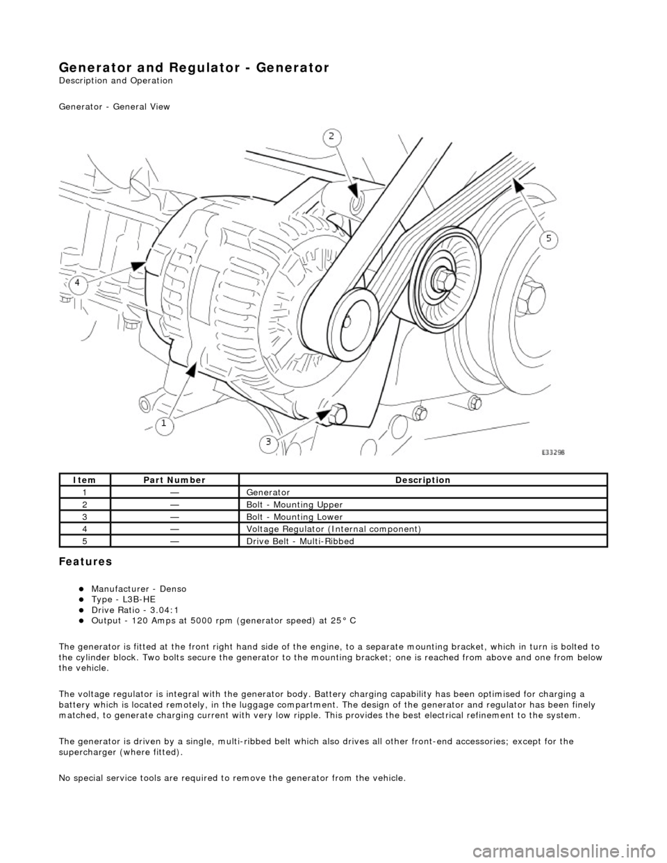
Generator - General View
Features
Manufacturer - Denso Type - L3B-HE Drive Ratio - 3.04:1 Output - 120 Amps at 5000 rpm (generator speed) at 25° C
The generator is fitted at the front right hand side of the engine, to a sepa rate mounting bracket, which in turn is bolted to
the cylinder block. Two bolts secure th e generator to the mounting bracket; one is reached from above and one from below
the vehicle.
The voltage regulator is integral with th e generator body. Battery charging capabi lity has been optimised for charging a
battery which is located remotely, in the luggage compartment. The design of the generator and regulator has been finely
matched, to generate charging current with very low ripple. This provides the best electrical refinement to the system.
The generator is driven by a single, multi-ribbed belt which also drives all other front-e nd accessories; except for the
supercharger (where fitted).
No special service tools are required to remove the generator from the vehicle.
ItemPart NumberDescription
1—Generator
2—Bolt - Mounting Upper
3—Bolt - Mounting Lower
4—Voltage Regulator (Internal component)
5—Drive Belt - Multi-Ribbed
Page 1883 of 2490

Belt tension is achieved by an automatic tensioner; neither the belt nor the tensioner require service apart from checking
the belt wear indicators at each normal service interval.
The minimum service life of the drive belt is 100,000 miles.
Never apply oil to the belt or to the belt tensioner.
Generator - Charging Circuit
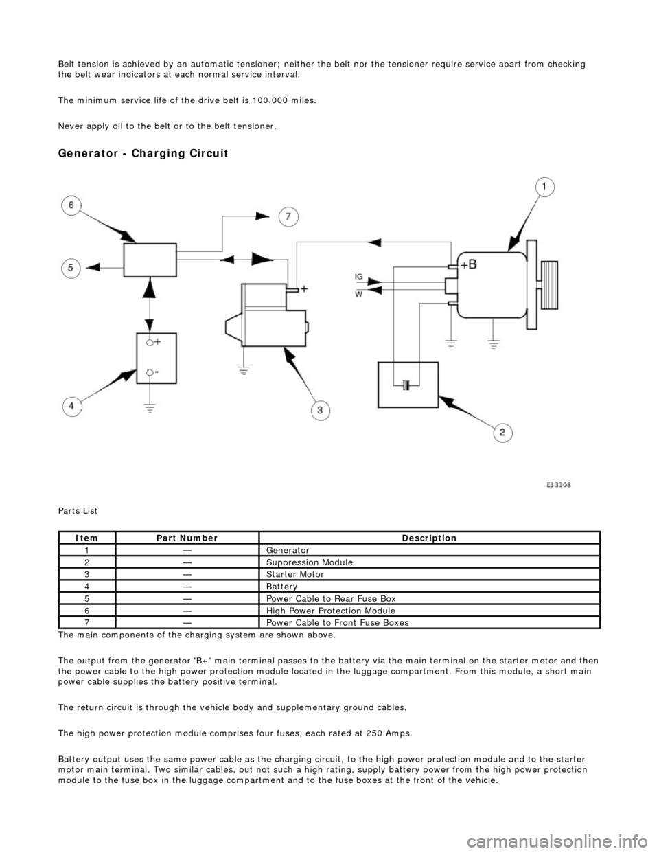
Parts List
The main components of the charging system are shown above.
The output from the generator 'B+' main te rminal passes to the battery via the main terminal on the starter motor and then
the power cable to the high power protection module located in the luggage compartment. From this module, a short main
power cable supplies the ba ttery positive terminal.
The return circuit is through the vehicle body and supplementary ground cables.
The high power protection mo dule comprises four fuses, each rated at 250 Amps.
Battery output uses the same power cable as the charging circ uit, to the high power protection module and to the starter
motor main terminal. Two similar cables, but not such a high rating, supply battery power from the high power protection
module to the fuse box in the luggage compartment an d to the fuse boxes at the front of the vehicle.
ItemPart NumberDescription
1—Generator
2—Suppression Module
3—Starter Motor
4—Battery
5—Power Cable to Rear Fuse Box
6—High Power Protection Module
7—Power Cable to Front Fuse Boxes