Page 1714 of 2490
Wi
th EM013 disconnected, check for battery voltage
between EM013/009 and ground BT020L.
1
B+ ?
Yes
GO t
o B13
No GO to B4
B4: CHECK
SUPPLY VOLTAGE
•
NOTE: Do not replace relay.
Page 1715 of 2490
W
ith relay 1 removed, check for battery voltage at relay
socket between pins 3 and 5.
1
B+
Yes GO to B5
No GO to B11
B5
: CHECK CIRCUIT CONTINUITY
•
NOTE: Do not replace relay.
Page 1718 of 2490
Us
ing a link lead, connect EM013/009 to ground BT020L.
1
W
i
th ignition energized, check for battery voltage at relay
socket between pins 2 and 1.
2
B+?
Yes
GO t
o B10
No GO to B8
B8: CH
ECK RELAY COIL CIRCUIT CONTINUITY
Page 1726 of 2490
Pinpoint test C: P0460
Wi
th conditions as in B14, measure the insulation
resistance between EM013/009 and BT009/003.
1
I s
the resistance > 10M OHM?
Yes Reconnect all plugs and replace relay 1.
GO to B16
No
B 16:
END
Perform
a
ppropriate service drive cycle and check for the
presence of DTC.
1
Has th
e fault code cleared?
Yes STOP
No Contact Jaguar Service
PI
NPOINT TEST C : C: P0460
T
E
ST CONDITIONS
D
E
TAILS/RESULTS/ACTIONS
C1
: RETRIEVE DTC
S
•
NOTE
: Battery and or ECM disconnection prior to scanning wi
ll erase all data, ensure that the correct DTC is present.
Page 1732 of 2490
Fu
el Tank and Lines - Fuel Level Sensor
Remov
a
l and Installation
Removal
Ins
tallation
1.
WA
RNING: BEFORE PROCEEDING, IT IS ESSENTIAL THAT THE
WARNING NOTES GIVEN IN SECTIO N 100-00 (UNDER THE HEADING
'SAFETY PRECAUTIONS') ARE READ AND UNDERSTOOD.
Remove the battery. For additional information, refer to Section 414
-01
Battery, Mounting and Cables
.
2.
Drain
the fuel tank using a suitable suction pump/tanker. If the On-
board Refueling Vapour Recovery (ORVR) system is fitted, refer to
Section 310
-00 Fu
el System
- Gen
e
ral Information
.
3. Remov
e the trunk front liner. For additional information, refer to
Section 501
-05 Interior Trim
and Ornamentation
.
4. D
isconnect the harness co
nnections to the sensor.
5. U
sing special tool 18G 1001, remo
ve the sensor retaining ring.
6.
Remov
e the sensor assembly and discard the seal.
1. Fitting a new level sensor is the reverse of the removal procedure,
noting that a new seal must be fitted.
Page 1733 of 2490

Fuel Tank and Li
nes - Fuel Pump
Re
moval and Installation
Remov
al
Installation
1.
WARNING: B
EFORE PROCEEDING, IT IS ESSENTIAL THAT
THE WARNING NOTES GIVEN IN SECTION 100-00 (UNDER THE
HEADING 'SAFETY PRECAUTIONS') ARE READ AND
UNDERSTOOD.
Remove the battery. For additional information, refer to Section
414
-0
1 Battery, Mounting and Cables
.
2.
Drain th
e fuel tank using a suitab
le suction pump/tanker. If the
On-board Refueling Vapour Recove ry (ORVR) system is fitted,
refer to Section 310
-00
Fuel System
- General
Information
.
3. R
emove the fuel tank. For addi
tional information, refer to Fuel
Tank
in this section.
4. Remove the fuel tank evaporativ e loss flange sealing ring. For
additional information, refer to Section 303
-13
.
5. R
emove fuel feed hose from tank.
U
sing special tool JD175, slacken fuel feed hose to tank
stub securing clip.
Di
sconnect hose from tank stub.
6. Remove fuel pump assembly.
R
elease bolt securing fuel
pump mounting bracket and
place assembly to front.
Slac
ken securing clip and disc
onnect hose from fuel pump.
R
emove link lead from fuel pump.
Re
move pump.
1. NOTE: Install new sealing ring to evaporative loss flange. For
additional information, refer to Section 303
-13
.
In
stallation is th
e reverse of the removal procedure.
Page 1734 of 2490

Fuel Tank and Lines - Fuel Tank
Re
mo
val and Installation
Remov
a
l
•
NO
TE: This removal/installation procedure is applicable to all tank assembly variants.
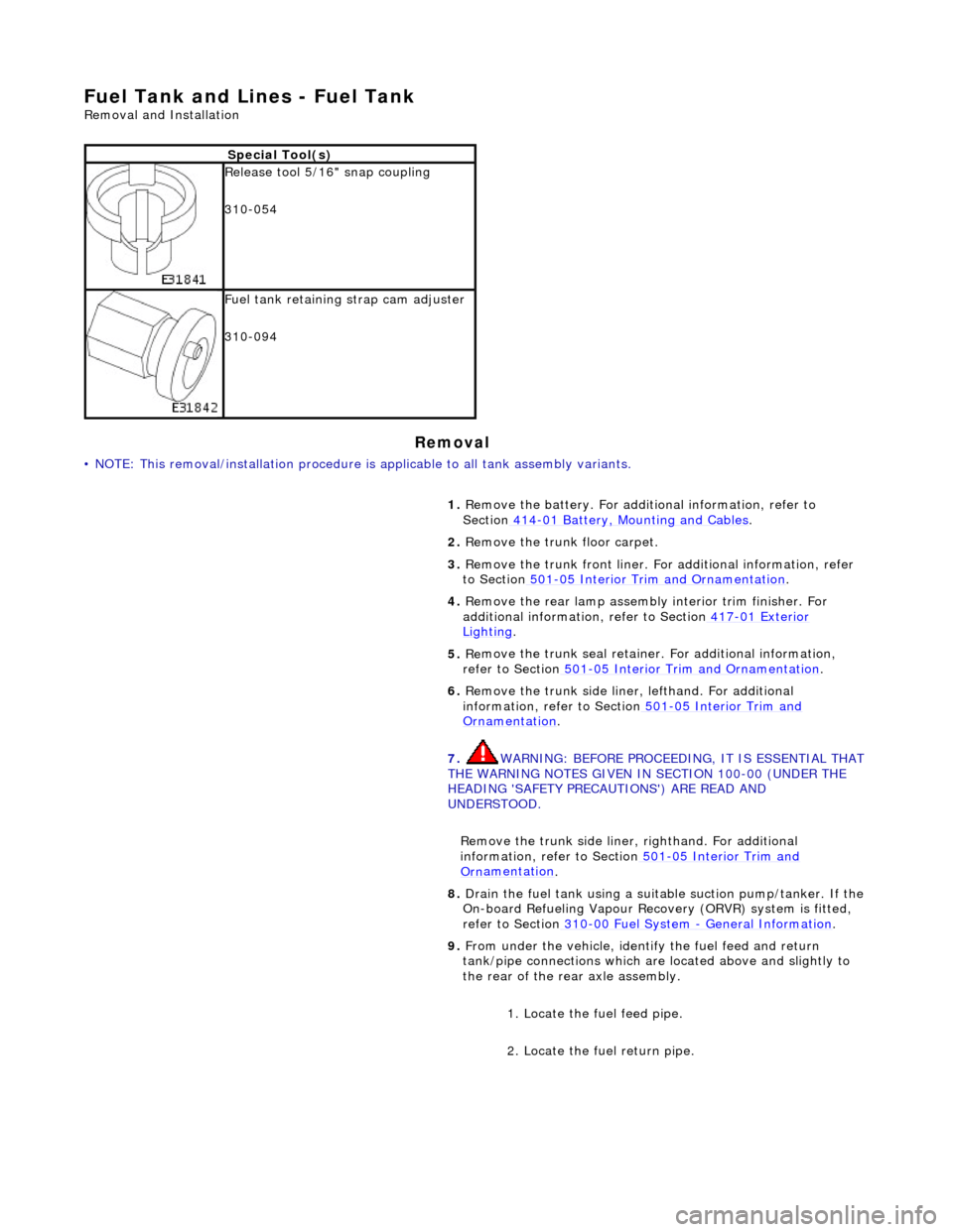
S
p
ecial Tool(s)
R
e
lease tool 5/16" snap coupling
310-054
F u
el tank retaining strap cam adjuster
310-094
1. Remove the battery. For additi onal information, refer to
Section 414
-01
Battery, Mounting and Cables
.
2. Re
move the trunk floor carpet.
3. Remove the trunk front liner. Fo r additional information, refer
to Section 501
-05
Interior Trim and Ornamentation
.
4. Re
move the rear lamp assembly interior trim finisher. For
additional information, refer to Section 417
-01
Exterior
Ligh
ting.
5. Re
move the trunk seal retainer
. For additional information,
refer to Section 501
-0 5
Interior Trim and Ornamentation
.
6. Re
move the trunk side liner, lefthand. For additional
information, refer to Section 501
-05
Interior Trim and
Or
n
amentation
.
7. WARNING: B E
FORE PROCEEDING, IT IS ESSENTIAL THAT
THE WARNING NOTES GIVEN IN SECTION 100-00 (UNDER THE
HEADING 'SAFETY PRECAUTIONS') ARE READ AND
UNDERSTOOD.
Remove the trunk side liner, righthand. For additional
information, refer to Section 501
-05
Interior Trim and
Or
n
amentation
.
8.
Drain th e fue
l tank using a suitab
le suction pump/tanker. If the
On-board Refueling Vapour Recove ry (ORVR) system is fitted,
refer to Section 310
-00 Fu
el System
- General
Information
.
9. Fr
om under the vehicle, identify the fuel feed and return
tank/pipe connections which are located above and slightly to
the rear of the rear axle assembly.
1. Locate the fuel feed pipe.
2. Locate the fuel return pipe.
Page 1740 of 2490

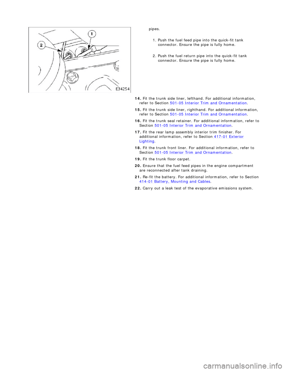
pipes.
1.
Push the fuel feed pipe into the quick-fit tank
connector. Ensu re the pipe is fully home.
2. Push the fuel return pi pe into the quick-fit tank
connector. Ensu re the pipe is fully home.
14. Fit the trunk side liner, lefthand. For additional information,
refer to Section 501
-0 5
Interior Trim and Ornamentation
.
15 . F
it the trunk side liner, righthan
d. For additional information,
refer to Section 501
-0 5
Interior Trim and Ornamentation
.
16 . F
it the trunk seal retainer. For a
dditional information, refer to
Section 501
-05
Interior Trim and Ornamentation
.
17 . F
it the rear lamp assembly
interior trim finisher. For
additional information, refer to Section 417
-01
Exterior
Ligh
ting.
18 . F
it the trunk front liner. For a
dditional information, refer to
Section 501
-05
Interior Trim and Ornamentation
.
19 . F
it the trunk floor carpet.
20. Ensure that the fuel feed pi pes in the engine compartment
are reconnected after tank draining.
21. Re-fit the battery. For additional information, refer to Section
414
-0 1
Battery, Mounting and Cables
.
22 . Carry ou
t a leak test of the evaporative emissions system.