Page 251 of 2490
19
.
Install a thread protector on axle shaft.
20
.
Release hub from axle shaft.
Position hu
b puller on hub studs. (204-011)
Inst
all securing nuts.
Progres
sively tighten
puller center bolt to release hub from
axle shaft splines.
21. Remove nuts and release puller from hub.
22. Remove thread protec tor from axle shaft.
23
.
Release handbrake cable from suspension mounting bracket.
Remove cable reta
ining clip.
Draw c
able through suspension mounting bracket
aperture.
24. Remove parking brake cable to hub carrier grommet.
Page 252 of 2490
25. Remove back plate.
Re
move four screws securing
back plate to hub carrier.
Withdraw back plate
complete
with parking brake cable.
26 . Remove h
ub and carrier.
With
draw pivot pin
.
R
e
move hub and carrier assemb
ly from wishbone and axle
shaft.
27 . R
emove shim from each end of pivot pin sleeve.
28. Withdraw pivot pin sleeve from hub carrier.
Page 257 of 2490
19
.
Install wheel speed sensor on hub carrier.
Posit
ion sensor on hub carrier
and install and tighten bolt
to 7-10Nm.
Conne
ct wheel speed sensor harness to sensor.
20
.
Using new tie strap, secure wh eel speed sensor harness to
brake hose clip.
21. Install parking brake shoe s. Refer to 70.40.05.
22
.
Install special tool (204-195) on studs and install securing
nuts.
23. Tighten hub nut to 304-336Nm.
Page 258 of 2490
24
. R
emove nuts and withdraw special tool (204-195) from hub
studs.
25. Install brake disc. Refer to operation 70.10.13.
26. Install rear wheel. Refer to section 204-04.
27. Remove stands and lower vehicl e. Refer to section 100-02.
28. Raise vehicle on four-post lift.
29 . Rout
e brake LH cable through equalizer.
30 . Inst
all cable in connecting clip.
31. Adjust parking brake cable. Refer to 70.35.10.
32. Lower four-post lift.
33. Apply parking brake.
34. Carry out rear wheel alignm ent check and adjust as
necessary. Refer to 204-02 Specification section.
Page 280 of 2490
Driveshaft -
Torques
Comp
onent
Nm
Bol
t
M12 - Jurid flexible coupling to
transmission and final drive flanges
75
-
88
Screw
-
Centre bearing to underbody
19
,5
- 26,5
Screw
-
Parking brake relay mounting bracket to underbody
19
,5
- 26,5_
Page 282 of 2490

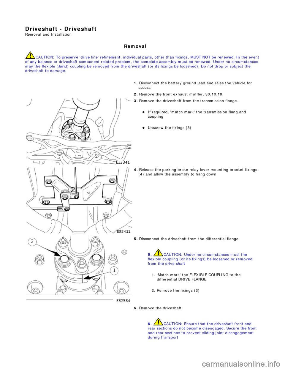
Driveshaft - Driveshaft
Remo
val and Installation
Remov
a
l
CAUTI
O
N: To preserve 'drive line' refine
ment, individual parts, other than fixings, MUST NOT be renewed. In the event
of any balance or driveshaft component related problem, the complete assembly must be renewed. Under no circumstances
may the flexible (Jurid) coupling be remo ved from the driveshaft (or its fixings be loosened). Do not drop or subject the
driveshaft to damage.
1. Disc
onnect the battery ground
lead and raise the vehicle for
access
2. Remove the front exha ust muffler, 30.10.18
3. Re
move the driveshaft from
the transmission flange.
If required, 'match mark'
the transmissi on flang and
coupling
Unscrew the fi xings (3)
4. Relea s
e the parking brake relay
lever mounting bracket fixings
(4) and allow the assembly to hang down
5. Disc onne
ct the driveshaft fr
om the differential flange
5. CAUTION: Under no circumstances must the
flexible coupling (or its fixings) be loosened or removed
from the drive shaft
1. 'Match mark' the FLEX IBLE COUPLING to the
differential DRIVE FLANGE
2. Remove the fixings (3)
6. Re
move the driveshaft
6. CAUTION: Ensure that the driveshaft front and
rear sections do not become disengaged. Secure the front
and rear sections to preven t sliding joint disengagement
during transport
Page 295 of 2490
R
ear Drive Axle/Differential - Drive Pinion Flange and Drive Pinion Seal
In-v
ehicle Repair
Remov
al
S
pecial Tool(s)
Drive sh
aft flange wrench
205-053
D
rive shaft flange remover replacer.
205-272
1. Di
sconnect the battery ground lead.
2. Raise the vehicle for access.
3. Disconnect the main parking br ake c
able at the compensator.
4. Release the parking brake relay lever mounting bracket and
allow the assembly to hang down.
R
emove the fixings (4).
Page 301 of 2490
7. Re
move the damper assembly
1. Mark the tool position on the spring with adhesive
tape
2. Remove the damper lower fixing
3. Remove the damper assembly
8. Repeat for the opposite hand spring / damper unit
9. Relea
se the parking brake cable
1. Disconnect the cable in-line connector
2. Remove the outer cable to frame clips (2)
3. Clear the cable through the frame
10
.
Remove the LH hub and axle shaft assembly
1. Remove the lower fulcrum shaft nut (1)
2. Remove and discard the axle shaft to drive flange nuts (4)
3. Turn the axle-shaft for ac cess to access the fixings for
step 2
4. Support the axle shaft a ssembly and remove the hub
fulcrum
5. Remove the hub and axle shaft assembly
6. Note the position of and remove the camber adjustment spacer
11. Repeat for the opposite hand