1998 JAGUAR X308 parking brake
[x] Cancel search: parking brakePage 399 of 2490

Parking Brake and Act
uation - Parking Brake Control Shroud
Re
moval and Installation
Remov
al
Installation
1.
Position ha
ndbrake lever fully up.
2. Remove trim from handbrake lever.
1. Release press stud at to p of handbrake lever trim.
2. Ease lower moulding away from boss at base of lever and slide trim upwards.
1. Slide trim over handbrake lever and position lower moulding
over boss.
2. Fasten press stud at top of trim.
3. Check that 'J' gate selector is in position P.
4. Lower handbrake lever, checki ng for freedom of movement.
5. Pull handbrake lever fully up.
Page 400 of 2490

Parking Brake and Actuation - P
arking Brake Shoes
Re
mo
val and Installation
Remov
a
l
W
A
RNING: BRAKE DUST, IF INHALED CAN DAMAGE YOUR
HEALTH. ALWAYS REMOVE BRAKE DUST USING A VACUUM
BRUSH. DO NOT USE A COMPRESSED-AIR LINE TO DISPERSE BRAKE DUST INTO THE ATMOSPHERE.
CAUTION: Replacement of nuts and bolts: Various thread-locking devices are used on nuts and bolts throughout the
vehicle. These devices restrict the number of times a nut or bolt can be used. See section 100-00 for information.
1. Ra
ise rear of vehicle and support
on stands. Refer to section
100-02.
2. Remove both rear wheels.
3. Remove both rear brake discs. Refer to operation 70.10.13.
4. Re
move front shoe retaining pin.
Align hub ac
cess hole with retaining pin.
Turn pin until
it rel
eases
from backing plate.
5. Remove adju ster assembly.
Move front shoe forwards.
Remove adju
ster assembly.
6. Re
move rear shoe retaining pin.
Al
ign hub ac
cess hole with retaining pin.
Turn pin until
it rel
eases
from backing plate.
7. Remove brake shoes from parkin g brake lever-mechanism and
remove shoes from vehicle.
8. Remove return sp rings from shoes.
Page 402 of 2490

plate.
Install front
shoe
retaining pin.
Align hu
b acc
ess hole.
Inst
al
l retaining pin.
5. Make sure brake shoes are seat ed correctly in adjuster and
lever mechanism.
6. Repeat procedure to install parking brake shoes on opposite
side of vehicle.
7. Install both rear br ake discs. Refer to operation 70.10.13.
8. Set parking brake. Refer to operation 70.35.37.
9. Fit rear wheels. See section 204-04.
10. Remove stands an d lower vehicle.
Page 403 of 2490

Parking Brake and Ac
tuat
ion - Parking Brake Warn ing Indicator Switch
Re
moval and Installation
Remov
al
Installation
1. R
emove driver seat for access. Refer to 76.70.01.
2. Raise hand lever fully.
3. Remove trim from hand lever. Refer to operation 76.13.63.
4. R
emove screws securing
switch to hand lever.
5. Di
sconnect electrical connector from switch.
1. Di
sconnect electrical connector from switch.
2. Install switch to hand lever.
Install and tigh
ten
screws to 3 Nm.
Page 1066 of 2490

Starting System - Starting System
Diagn
osis and Testing
I
n
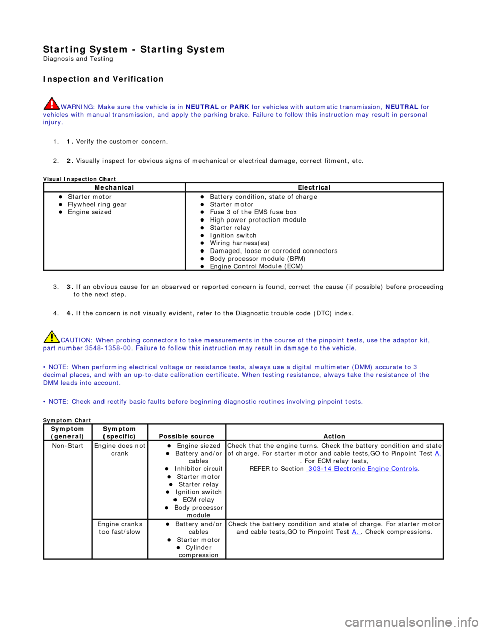
spection and Verification
W
A
RNING: Make sure
the vehicle is in NEUTRAL or PARK for vehicles with au tomatic transmission, NEUTRAL for
vehicles with manual transmissi on, and apply the parking brake. Failure to foll ow this instruction may result in personal
injury.
1. 1. Verify the customer concern.
2. 2. Visually inspect for obvious signs of mechanical or electrical damage, correct fitment, etc.
Vi
sual Inspection Chart
3.
3. If an obvi
ous cause for an observed or
reported concern is found, correct th e cause (if possible) before proceeding
to the next step.
4. 4. If the concern is not visually evident, refer to the Diagnostic trouble code (DTC) index.
CAUTION: When probing connectors to take measurements in the course of the pinpoint tests, use the adaptor kit,
part number 3548-1358-00. Failure to follow this in struction may result in damage to the vehicle.
• NOTE: When performing electrical voltag e or resistance tests, always use a digital multimeter (DMM) accurate to 3
decimal places, and with an up-t o-date calibration certificate. When testing resistance, always take the resistance of the
DMM leads into account.
• NOTE: Check and rectify basic faults before beginning diagnostic ro utines involving pinpoint tests.
Sym
ptom Chart
MechanicalElectrical
Starte
r motor
Flywheel
ring gear
Engine
s
eized
Batter
y condition, state of charge
Starte
r motor
F
u
se 3 of the EMS fuse box
High
power protec ti
on module
Starter relay Ignition switc
h
W
i
ring harness(es)
Damaged, loose or corroded connector
s
Body processor module (B
PM)
Engine
C
ontrol Module (ECM)
Sy
m
ptom
(
gene r
al)
Sy
m
ptom
(specific)
Possib l
e source
Acti
o
n
No
n
-Start
Engine does
not
crankEngine s
iezed
Batt
ery and
/or
cables
Inhibitor circuit St arte
r motor
Starter relay Ignition switc
h
ECM relay Body processor
modu le
Check that
the engine turns. Check the battery condition and state
of charge. For starter motor and ca ble tests,GO to Pinpoint Test A.
. For ECM relay
tests,
REFER to Section 303
-14
Electronic Engine Controls
.
Engine
c
ranks
too fast/slow
Batt ery and
/or
cables
St arte
r motor
Cy
linder
com
pression
Check the battery con
dition
and st
ate of charge. For starter motor
and cable tests,GO to Pinpoint Test A.
. Chec
k compressions.
Page 1390 of 2490

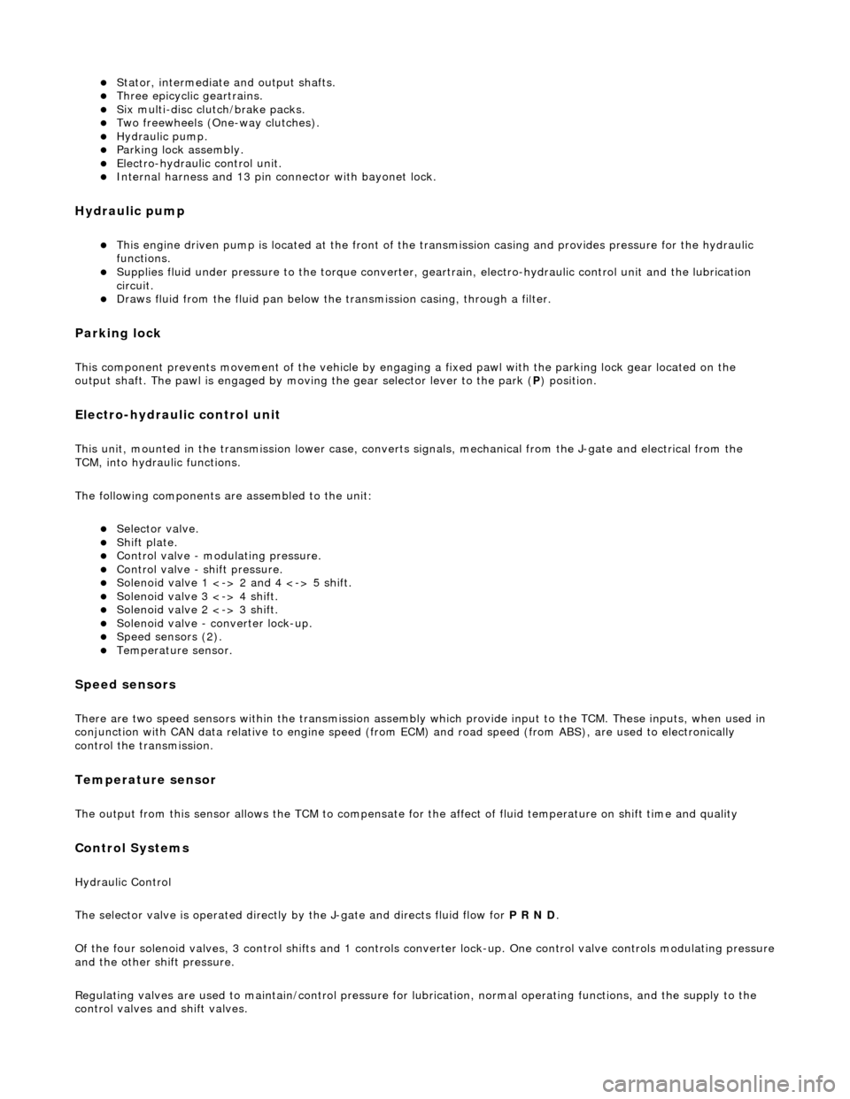
Stator, intermediate and output shafts. Three epicyclic geartrains. Six multi-disc clutch/brake packs. Two freewheels (One-way clutches). Hydraulic pump. Parking lock assembly. Electro-hydraulic control unit. Internal harness and 13 pin connector with bayonet lock.
Hydraulic pump
This engine driven pump is located at the front of the transmission casing and provides pressure for the hydraulic
functions.
Supplies fluid under pressure to the torq ue converter, geartrain, electro-hydraulic control unit and the lubrication
circuit.
Draws fluid from the fluid pa n below the transmission casing, through a filter.
Parking lock
This component prevents movement of th e vehicle by engaging a fixed pawl with the parking lock gear located on the
output shaft. The pawl is engaged by movi ng the gear selector lever to the park (P) position.
Electro-hydraulic control unit
This unit, mounted in the transmission lower case, converts signals, mechanical from the J-gate and electrical from the
TCM, into hydraulic functions.
The following components ar e assembled to the unit:
Selector valve. Shift plate. Control valve - modulating pressure. Control valve - shift pressure. Solenoid valve 1 <-> 2 and 4 <-> 5 shift. Solenoid valve 3 <-> 4 shift. Solenoid valve 2 <-> 3 shift. Solenoid valve - converter lock-up. Speed sensors (2). Temperature sensor.
Speed sensors
There are two speed sensors within the transmission assembly which provide input to the TCM. These inputs, when used in
conjunction with CAN data relative to engine speed (from ECM) and road speed (from ABS), are used to electronically
control the transmission.
Temperature sensor
The output from this sensor allows the TCM to compensate for the affect of fluid temperature on shift time and quality
Control Systems
Hydraulic Control
The selector valve is operated directly by the J-gate and directs fluid flow for P R N D.
Of the four solenoid valves, 3 control shifts and 1 controls converter lock-up. One control valve controls modulating pressure
and the other shift pressure.
Regulating valves are used to maintain/control pressure for lu brication, normal operating functions, and the supply to the
control valves and shift valves.
Page 1501 of 2490

Selector lever:
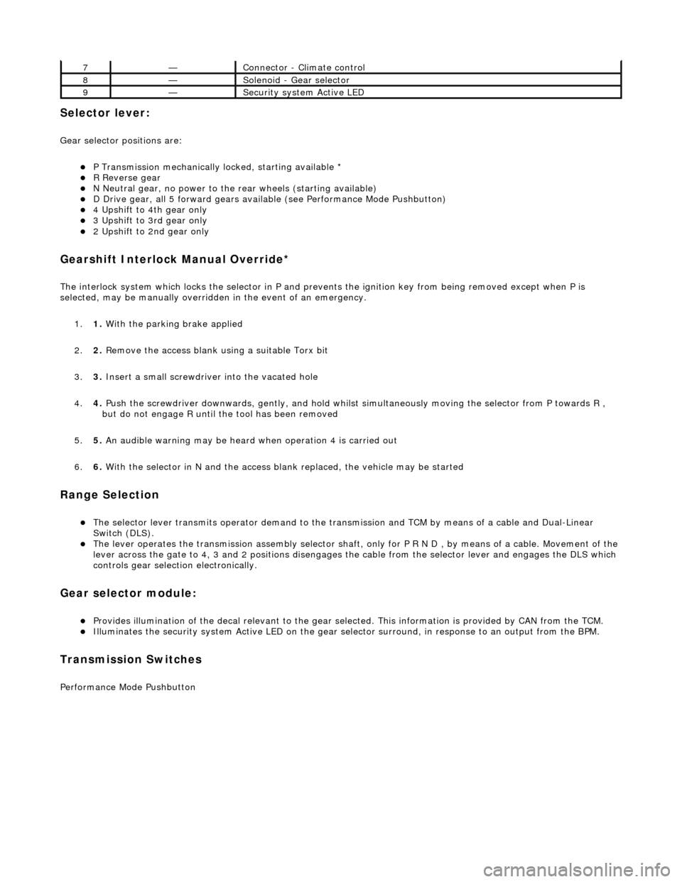
Gear selector positions are:
P Transmission mechanically locked, starting available * R Reverse gear N Neutral gear, no power to the rear wheels (starting available) D Drive gear, all 5 forward gears available (see Performance Mode Pushbutton) 4 Upshift to 4th gear only 3 Upshift to 3rd gear only 2 Upshift to 2nd gear only
Gearshift Interlock Manual Override*
The interlock system which locks the sele ctor in P and prevents the ignition key from being removed except when P is
selected, may be manually overridden in the event of an emergency.
1. 1. With the parking brake applied
2. 2. Remove the access blank using a suitable Torx bit
3. 3. Insert a small screwdriver into the vacated hole
4. 4. Push the screwdriver downwards, gently, and hold whilst simultaneously moving the selector from P towards R ,
but do not engage R until the tool has been removed
5. 5. An audible warning may be heard when operation 4 is carried out
6. 6. With the selector in N and the access bl ank replaced, the vehicle may be started
Range Selection
The selector lever transmits operator demand to the transmission and TCM by means of a cable and Dual-Linear
Switch (DLS).
The lever operates the transmission assemb ly selector shaft, only for P R N D , by means of a cable. Movement of the
lever across the gate to 4, 3 and 2 positions disengages th e cable from the selector lever and engages the DLS which
controls gear selection electronically.
Gear selector module:
Provides illumination of the decal relevant to the gear sele cted. This information is provided by CAN from the TCM. Illuminates the security system Active LED on the gear selector surround, in response to an output from the BPM.
Transmission Switches
Performance Mode Pushbutton
7—Connector - Climate control
8—Solenoid - Gear selector
9—Security system Active LED
Page 1504 of 2490

Automatic Transmission/Transaxle External Controls - 4.0L SC V8 - AJ26 -
External Controls
Diagnosis and Testing
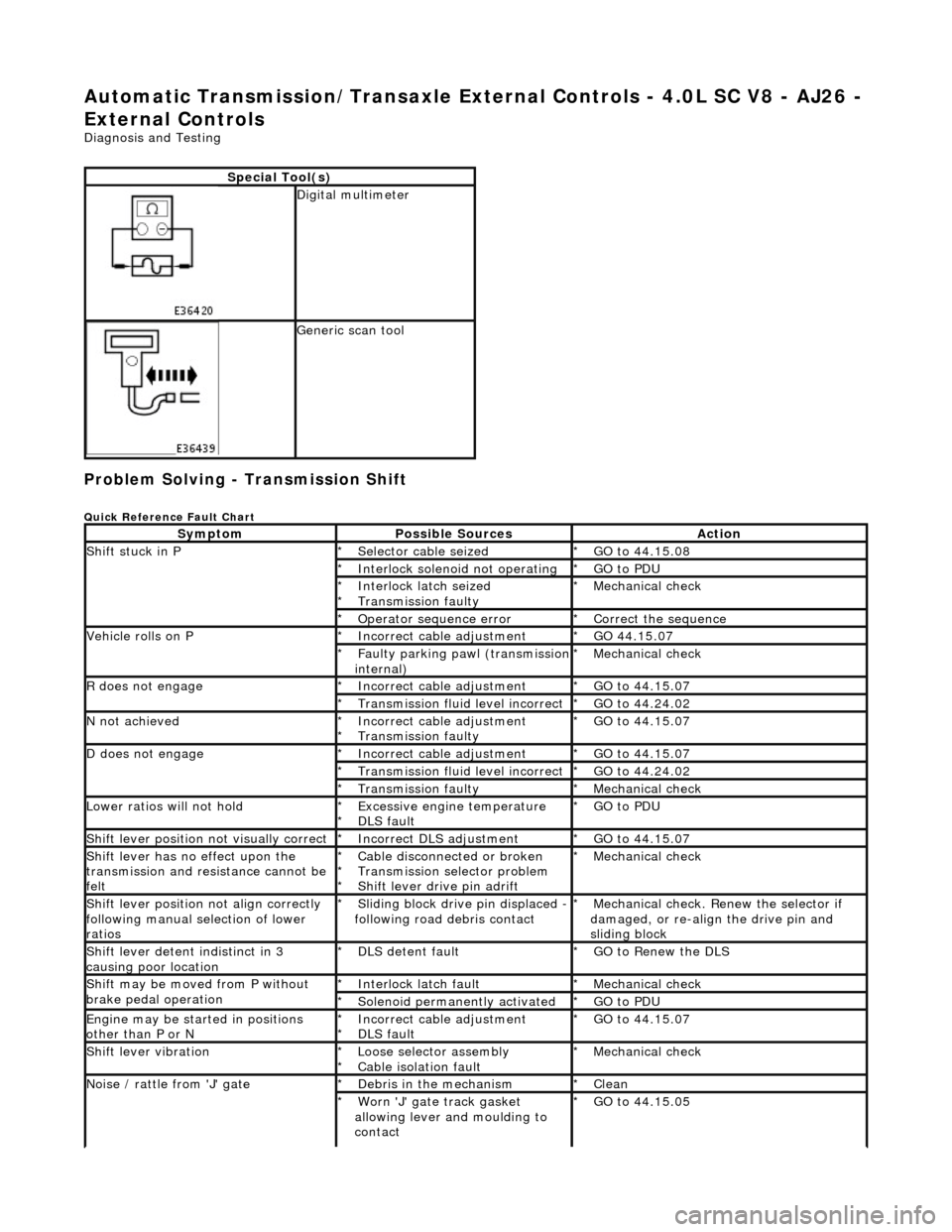
Problem Solving - Transmission Shift
Quick Reference Fault Chart
Special Tool(s)
Digital multimeter
Generic scan tool
SymptomPossible SourcesAction
Shift stuck in P Selector cable seized
*GO to 44.15.08
*
Interlock solenoid not operating
*GO to PDU
*
Interlock latch seized
Transmission faulty
*
*Mechanical check
*
Operator sequence error
*Correct the sequence
*
Vehicle rolls on P Incorrect cable adjustment
*GO 44.15.07
*
Faulty parking pawl (transmission internal)
*Mechanical check
*
R does not engageIncorrect cable adjustment
*GO to 44.15.07
*
Transmission fluid level incorrect
*GO to 44.24.02
*
N not achievedIncorrect cable adjustment
Transmission faulty
*
*GO to 44.15.07
*
D does not engageIncorrect cable adjustment *GO to 44.15.07
*
Transmission fluid level incorrect
*GO to 44.24.02
*
Transmission faulty
*Mechanical check
*
Lower ratios will not holdExcessive engine temperature
DLS fault
*
*GO to PDU
*
Shift lever position not visually correctIncorrect DLS adjustment
*GO to 44.15.07
*
Shift lever has no effect upon the
transmission and resistance cannot be
feltCable disconnected or broken
Transmission selector problem
Shift lever drive pin adrift
*
*
*Mechanical check
*
Shift lever position not align correctly
following manual selection of lower
ratiosSliding block drive pin displaced - following road debris contact
*Mechanical check. Renew the selector if
damaged, or re-align the drive pin and
sliding block
*
Shift lever detent indistinct in 3
causing poor locationDLS detent fault
*GO to Renew the DLS
*
Shift may be moved from P without
brake pedal operationInterlock latch fault
*Mechanical check
*
Solenoid permanently activated
*GO to PDU
*
Engine may be started in positions
other than P or N Incorrect cable adjustment
DLS fault
*
*GO to 44.15.07
*
Shift lever vibrationLoose selector assembly
Cable isolation fault
*
*Mechanical check
*
Noise / rattle from 'J' gateDebris in the mechanism
*Clean
*
Worn 'J' gate track gasket
allowing lever and moulding to
contact
*GO to 44.15.05
*