Page 1765 of 2490
Climate Co
ntrol System - General
Information - Refrigerant Adding
Gen
eral Procedures
CAUTION: If oil was drawn out during the recovery process, the correct amount may be added directly from the
recovery, recycle and recharge station (if so equipped) prior to the charging process. It must be stressed that the need to
protect compressor oil from moisture is vital, observe the pr ocedures in HANDLING LUBRICATING OIL and those concerning
excessive engine speed.
1. In order that the
air conditioning system may operate
efficiently it must contain a full refrigerant charge. The
indications of some system defects, and the results of certain
tests, will show that a low charge is the most probable cause of
the fault. In such cases the ch arge should be recovered from
the system, the weight noted, and the correct amount added.
Should refrigerant be added in liquid form, the engine speed
must not exceed 2000 rpm for a period of two minutes after
first running the compressor. If the engine speed is excessive,
compressor damage may occur du e to the lubricating oil and
the liquid refrigerant being initia lly forced around the system as
a 'slug', thus taking oil away from the compressor. These
marginal lubrication conditions in the compressor will cease as
the refrigerant becomes gaseous.
Never attempt to estimate the amount of refrigerant in a
system. Always recover and rech arge with the correct charge
weight; this is the only accurate method.
Page 1769 of 2490
Air Distribution and Filtering - Air Distri
bution and Filtering
Description an
d Operation
Air Distribution
Ou
tside air enters the plen
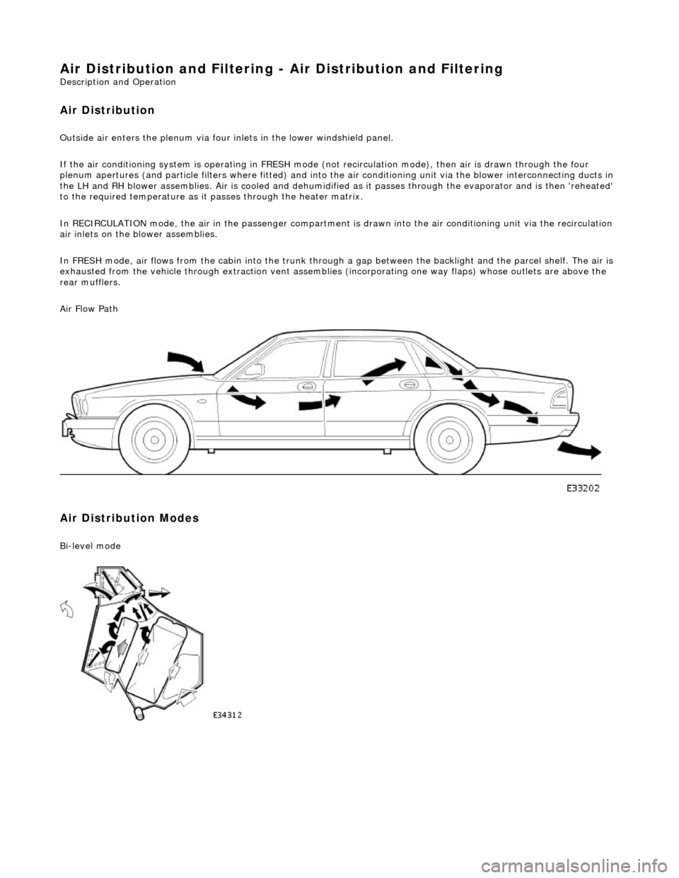
um via four inlets in the lower windshield panel.
If the air conditioning system is operating in FRESH mode (not recirculation mode), then air is drawn through the four
plenum apertures (and particle filters where fitted) and into the air conditioni ng unit via the blower interconnecting ducts in
the LH and RH blower assemblies. Air is c ooled and dehumidified as it passes through the evaporator and is then 'reheated'
to the required temperature as it passes through the heater matrix.
In RECIRCULATION mode, the air in the pass enger compartment is drawn into the air conditioning unit via the recirculation
air inlets on the blower assemblies.
In FRESH mode, air flows from the cabin into the trunk through a gap between the backlight and the parcel shelf. The air is
exhausted from the vehicle through extraction vent assemblies (incorporating one way flaps) whose outlets are above the
rear mufflers.
Air Flow Path
Air Distribution Modes
Bi
-level mode
Page 1773 of 2490
Ai
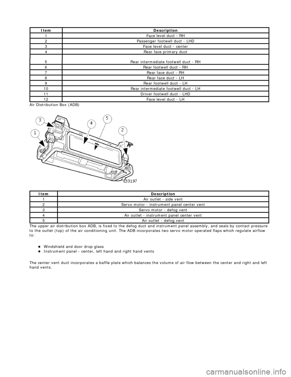
r Distribution Box (ADB)
The upper air distribution box ADB, is fixed to the defog duct and instrument panel assembly, and seals by contact pressure
to the outlet (top) of the air conditioning unit. The ADB inco rporates two servo motor operated flaps which regulate airflow
to:
Windshield and door drop
glass
Instrument panel
- center, left
hand and right hand vents
The center vent duct incorporat es a baffle plate which balances the volume of air flow between the center and right and left
hand vents.
5R
ear intermediate footwell duct - RH
6R
ear footwell duct - RH
7R
ear face duct - RH
8R
ear face duct - LH
9R
ear footwell duct - LH
10R
ear intermediate footwell duct - LH
11D
river footwell duct - LHD
12Fac
e level duct -
LH
It
em
De
scription
1Ai
r outlet - side vent
2Servo motor -
instrume
nt panel center vent
3Servo motor -
defog vent
4Ai
r outlet - instrume
nt panel center vent
5Ai
r outlet - defog vent
It
em
De
scription
1Fac
e level duct - RH
2Passenger footwel
l duct - LHD
3Fac
e level duct - center
4Rear
face primary duct
Page 1788 of 2490
Heating and Ventilation - Heater Core and Evaporator Core Housing
Removal and Installation
Removal
1. Disconnect battery ground cable (IMPORTANT, see SRO
86.15.19 for further information).
2. Recover refrigerant from air co nditioning system; refer to
82.30.30.
3. Drain radiator coolant only; refer to 26.10.01 or (SC)
26.10.01.
4. Remove instrument panel for access, refer to 76.46.01.
5. From under the hood: Disconnect air conditioning pipes at the
evaporator.
1. Remove bolts.
2. Discard O-rings.
3. Install suitable blanking plugs.
6. Disconnect heater hoses from heater matrix pipes.
1. Release spring band clips and disconnect heater hoses.
2. Install suitable blanking plugs.
7. From inside the vehicle: re move driver footwell duct.
Remove screw.
Remove duct.
8. Remove upper steering column lower fixings.
1. Remove nut.
2. Remove bolt.
Page 1797 of 2490
19. Reconnect air conditioning pipes at the evaporator.
Remove blanking plugs.
Install, fully seat and lubr icate new O-ring seals.
Install bolts.
20. Install instrument pane l; refer to 76.46.01.
21. Recharge air conditioning system; refer to 82.30.30.
22. Re-fill cooling system; refer to 26.10.01 or (SC) 26.10.01.
23. Reconnect battery ground cable (IMPORTANT, see SRO
86.15.15 for further information).
Page 1798 of 2490
Air Conditioning - Air Conditioning
Description and Operation
Introduction
Parts List
The climate control system features fully automatic control of temperature, blower speed (airflow) and air distribution to
maintain optimum comfort under most driving conditions.
Manual controls are provided to allow the operator to over-ride automatic operation.
System Features
ItemPart NumberDescription
1—Fascia panel with integral ducting
2—Heater / cooler assembly
3—A/CCM
4—Blower LH and RH
5—Plenum
6—Control panel
7—Solar sensor
8—Assembly valve - water
9—Assembly pump - water
10—Temperature sensor - external
11—Compressor
12—Pressure switch - 4 level
13—Motorized in-car aspirator (LHD shown)
14—Receiver drier
15—Condenser
Page 1799 of 2490
Twin blower assemblies Center mounted evaporator, heater and air distribution unit Electric solenoid water valve controlled heating Electric water pump assembly Servo motor driven air distribution flaps Dedicated side glass defrost / demist vents External temperature sensor Motorised in-car aspirator Solar sensor
Electronic Control Panel
Liquid Crystal Display (LCD) Digital temperature display Manual fan speed level External temperature display Celsius / Fahrenheit selection Heated windshield switch (where fitted) Heated backlight switch Defrost switch Manual airflow distribution overrides (4) Access to self diagnostic system and error codes
Sensors
External ambient temperature sensor Motorized in-car aspirator Heater matrix temperature sensor Evaporator temperature sensor Solar sensor
These sensors feedback information to the Air Conditioning Control Module (A/CCM) which automatically adjusts air
temperature, airflow volume and distributi on from the air conditioning unit to maintain a stable passenger compartment
average temperature under changing weather conditions.
Major Components
Page 1801 of 2490
Condenser:
Multi-pass fin-over-tube type, mounted in front of the engine cooling pack and directly to the radiator.
Pressure (Bitron) switch:
Located in the discharge pipe. Provides a signal, via the A/CCM, to th e ECM, to disengage the compressor clut ch should the refrigerant pressure be
< 2 bar or > 30 bar.
Provides a hard-wired signal to the ECM, to switch the cool ing fans to HIGH speed at 22 bar rising pressure and to
LOW speed at 17,5 bar falling pressure.
Provides a hard-wired signal to the ECM, to switch the radiator cooling fans to LOW speed at 12 bar rising pressure
and to switch the fans OFF at 8 bar falling pressure.
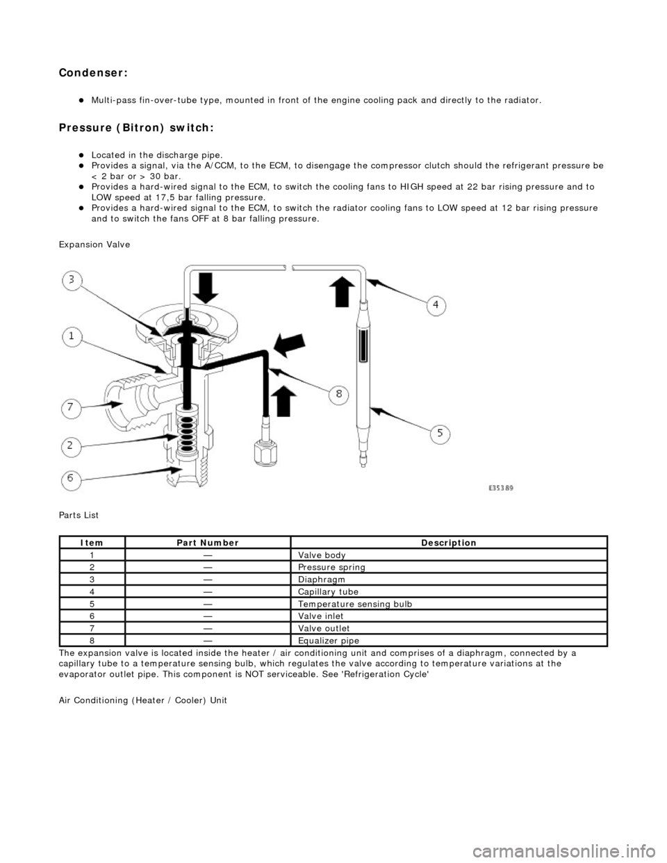
Expansion Valve
Parts List
The expansion valve is located inside the heater / air conditioning unit and comprises of a diaphragm, connected by a
capillary tube to a temperat ure sensing bulb, which regulates the valve according to temperature variations at the
evaporator outlet pipe. This component is NOT serviceable. See 'Refrigeration Cycle'
Air Conditioning (Heater / Cooler) Unit
ItemPart NumberDescription
1—Valve body
2—Pressure spring
3—Diaphragm
4—Capillary tube
5—Temperature sensing bulb
6—Valve inlet
7—Valve outlet
8—Equalizer pipe