Page 1820 of 2490
3. Tighten fixings to specification (8-10 Nm).
4. Tighten fixings to specification (8-10 Nm).
5. Recharge air conditioning system; refer to 82.30.30.
Page 1821 of 2490
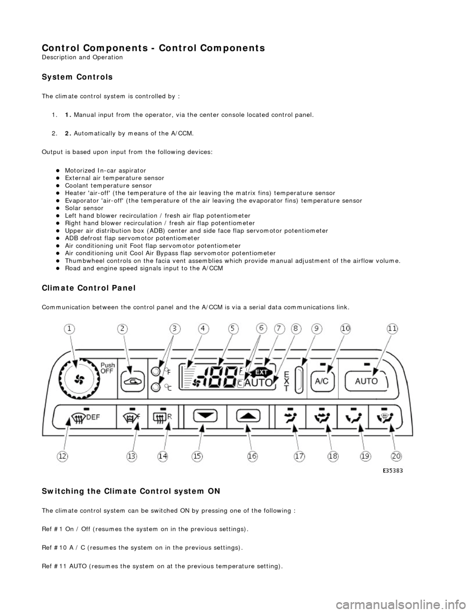
Control Components - Control Components
Description and Operation
System Controls
The climate control system is controlled by : 1. 1. Manual input from the operator, via the center console located control panel.
2. 2. Automatically by means of the A/CCM.
Output is based upon input from the following devices:
Motorized In-car aspirator External air temperature sensor Coolant temperature sensor Heater 'air-off' (the temperature of the air leaving the matrix fins) temperature sensor Evaporator 'air-off' (the temperature of the air leaving the evaporator fins) temperature sensor Solar sensor Left hand blower recirculation / fresh air flap potentiometer Right hand blower recirculation / fresh air flap potentiometer Upper air distribution box (ADB) center and side face flap servomotor potentiometer ADB defrost flap servomotor potentiometer Air conditioning unit Foot flap servomotor potentiometer Air conditioning unit Cool Air Bypass flap servomotor potentiometer Thumbwheel controls on the facia vent assemblies which provide manu al adjustment of the airflow volume. Road and engine speed signals input to the A/CCM
Climate Control Panel
Communication between the control panel and the A/CCM is via a serial data communications link.
Switching the Climate Control system ON
The climate control system can be switched ON by pressing one of the following :
Ref #1 On / Off (resumes the system on in the previous settings).
Ref #10 A / C (resumes the system on in the previous settings).
Ref #11 AUTO (resumes the system on at the previous temperature setting).
Page 1827 of 2490
Maximum Cooling (temperature setting LO)
Air Conditioning Control Module (A/CCM)
Location
The A/CCM is located on the right hand side of the air conditioning unit and controls all system functions.
The temperature within the passenger compartment is continually compared with the temperature selected on the control
panel LCD. The A/CCM receives data input signals and compares these with signal s from the system temperature sensors
and feedback devices. Based on this information the A/CCM adjusts the air outlet temperatur e, airflow and distribution from
the air conditioning system in to the passenger compartment.
Identification
ItemControlOverride Allowed
Water valveFully closed (energised)-
BlowerMaximumYes
Fresh / recircRecirculationYes
Air distributionFace (state lamp OFF)Yes
A/C systemONYes
Cool air by-passFully open-
Page 1829 of 2490
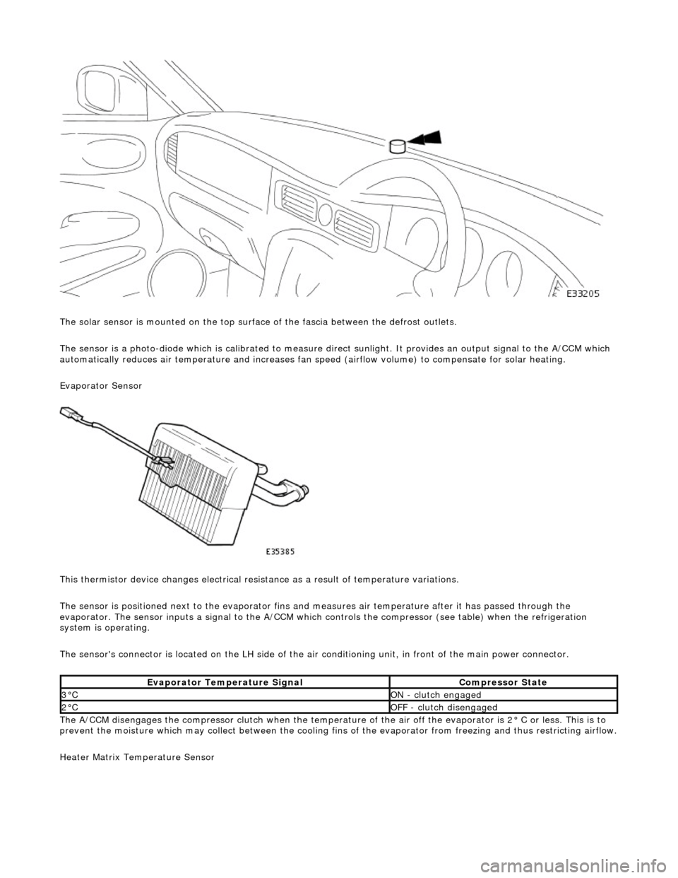
The solar sensor is mounted on the top surface of the fascia between the defrost outlets.
The sensor is a photo-diode which is calibr ated to measure direct sunlight. It provides an output signal to the A/CCM which
automatically reduces air temperature an d increases fan speed (airflow volume) to compensate for solar heating.
Evaporator Sensor
This thermistor device changes electrical resistance as a result of temperature variations.
The sensor is positioned next to the evaporator fins and measures air temper ature after it has passed through the
evaporator. The sensor inputs a signal to the A/CCM which controls the compress or (see table) when the refrigeration
system is operating.
The sensor's connector is located on the LH side of the air conditioning unit, in front of the main power connector.
The A/CCM disengages the compressor clutch when the temperature of the air off the evaporator is 2° C or less. This is to
prevent the moisture which may collect between the cooling fins of the evaporator from freezing and thus restricting airflow.
Heater Matrix Temperature Sensor
Evaporator Temperature SignalCompressor State
3°CON - clutch engaged
2°COFF - clutch disengaged
Page 1830 of 2490
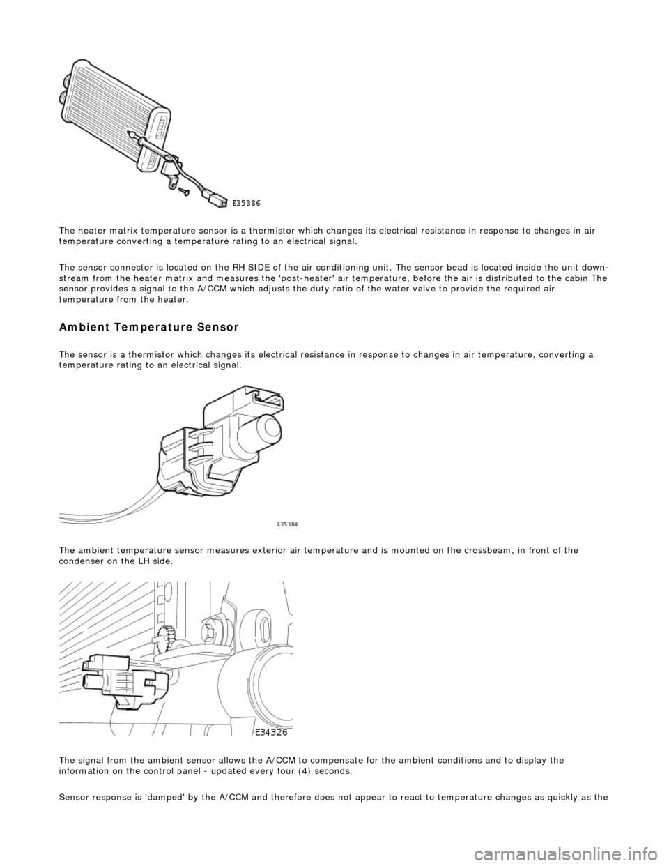
The heater matrix temperature sensor is a thermistor which changes its electrical resistance in response to changes in air
temperature converting a temperature rating to an electrical signal.
The sensor connector is located on the RH SIDE of the air conditioning unit. The sensor bead is located inside the unit down-
stream from the heater matrix and measures the 'post-heater' air temperature, before the air is distribu ted to the cabin The
sensor provides a signal to the A/CCM which adjusts the duty ratio of the water valve to provide the required air
temperature from the heater.
Ambient Temperature Sensor
The sensor is a thermistor which changes its electrical resistance in response to changes in air temperature, converting a
temperature rating to an electrical signal.
The ambient temperature sensor measures exterior air temper ature and is mounted on the crossbeam, in front of the
condenser on the LH side.
The signal from the ambient sensor allo ws the A/CCM to compensate for the ambient conditions and to display the
information on the control panel - updated every four (4) seconds.
Sensor response is 'damped' by the A/CCM and ther efore does not appear to react to temperature chan
ges as quickly as the
Page 1831 of 2490
other sensors. This feature prevents the effects of sudden changes in air outlet temperatures due to factors such as:
Recirculating air from the engine cooling pack at low vehicle speeds Sudden changes in ambient temperature The effects of water splash
Motorised In-car Aspirator.
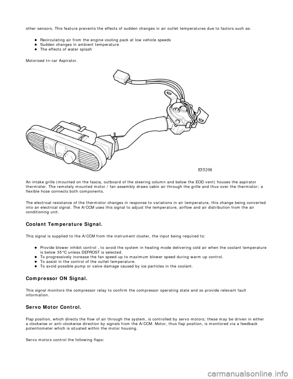
An intake grille (mounted on the fascia , outboard of the steering column and below the EOD vent) houses the aspirator
thermister. The remotely mounted motor / fan assembly draws ca bin air through the grille and thus over the thermistor; a
flexible hose connects both components.
The electrical resistance of the thermistor changes in response to variations in air temperatur e, this change being converted
into an electrical signal. The A/CCM uses this signal to adjust the temperature, airflow and air distribution from the air
conditioning unit.
Coolant Temperature Signal.
This signal is supplied to the A/CCM from the instrument cluster, the input being required to:
Provide blower inhibit control , to avoid the system in heat ing mode delivering cold air when the coolant temperature is below 35°C unless DEFROST is selected. To progressively increase the fan speed up to maximum blower speed during warm up control. To assist in the control of the outlet temperature. To avoid possible pump or valve damage ca used by ice particles in the coolant.
Compressor ON Signal.
This signal monitors the compressor relay to confirm the compressor operating state and so provide relevant fault
information.
Servo Motor Control.
Flap position, which directs the flow of air through the system, is controlled by servo motors; these may be driven in either
a clockwise or anti-clockwise direction by signals from the A/ CCM. Motor, thus flap position, is monitored via a feedback
potentiometer which is situated within the motor housing.
Servo motors control the following flaps:
Page 1832 of 2490
RH and LH Air Intake (Fresh / Recirc) Center Vent Defrost Foot Cool Air Bypass
Blower Motor Control.
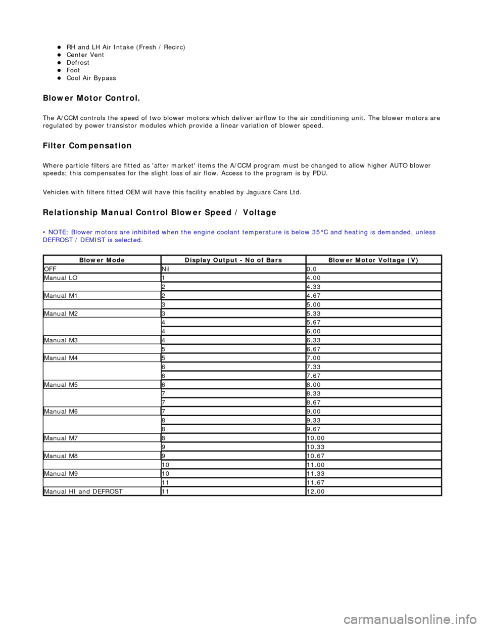
The A/CCM controls the speed of two blower motors which deliver airflow to the air conditioning unit. The blower motors are
regulated by power transistor modules which pr ovide a linear variation of blower speed.
Filter Compensation
Where particle filters are fitted as 'after market' items the A/CCM program must be changed to allow higher AUTO blower
speeds; this compensates for the slight loss of air flow. Access to the program is by PDU.
Vehicles with filters fitted OEM will have this facility enabled by Jaguars Cars Ltd.
Relationship Manual Contro l Blower Speed / Voltage
• NOTE: Blower motors are inhibited when the engine coolant temperature is below 35°C and heating is demanded, unless
DEFROST / DEMIST is selected.
Blower ModeDisplay Output - No of BarsBlower Motor Voltage (V)
OFFNil0.0
Manual LO14.00
24.33
Manual M124.67
35.00
Manual M235.33
45.67
46.00
Manual M346.33
56.67
Manual M457.00
67.33
67.67
Manual M568.00
78.33
78.67
Manual M679.00
89.33
89.67
Manual M7810.00
910.33
Manual M8910.67
1011.00
Manual M91011.33
1111.67
Manual HI and DEFROST1112.00
Page 1835 of 2490
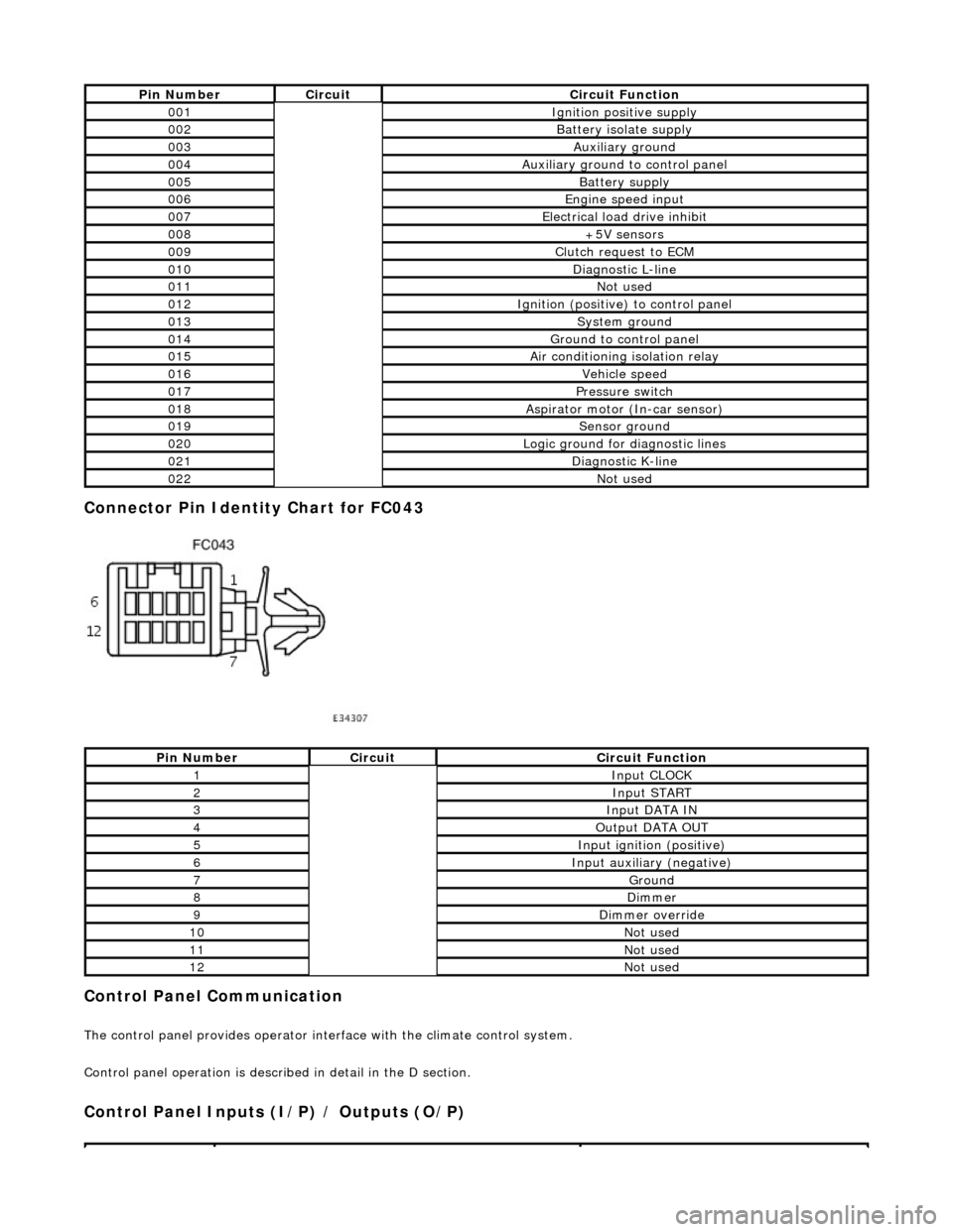
Connector Pin Identity Chart for FC043
Control Panel Communication
The control panel provides operator interface with the climate control system.
Control panel operation is described in detail in the D section.
Control Panel Inputs (I/P) / Outputs (O/P)
Pin NumberCircuitCircuit Function
001Ignition positive supply
002Battery isolate supply
003Auxiliary ground
004Auxiliary ground to control panel
005Battery supply
006Engine speed input
007Electrical load drive inhibit
008+5V sensors
009Clutch request to ECM
010Diagnostic L-line
011Not used
012Ignition (positive) to control panel
013System ground
014Ground to control panel
015Air conditioning isolation relay
016Vehicle speed
017Pressure switch
018Aspirator motor (In-car sensor)
019Sensor ground
020Logic ground for diagnostic lines
021Diagnostic K-line
022Not used
Pin NumberCircuitCircuit Function
1Input CLOCK
2Input START
3Input DATA IN
4Output DATA OUT
5Input ignition (positive)
6Input auxiliary (negative)
7Ground
8Dimmer
9Dimmer override
10Not used
11Not used
12Not used