Page 1802 of 2490

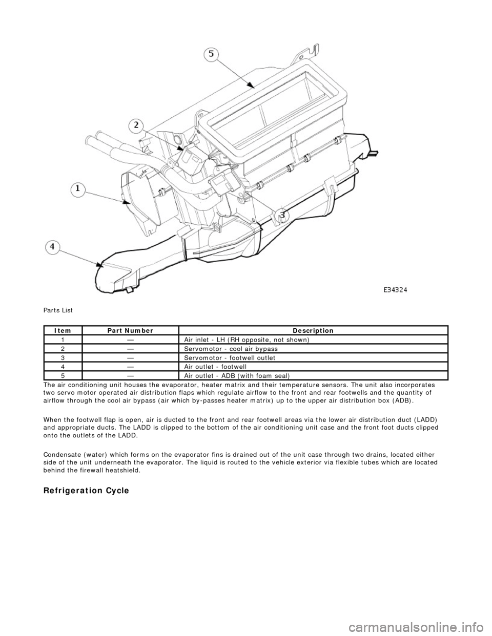
Parts List
The air conditioning unit houses the evap orator, heater matrix and their temperatur e sensors. The unit also incorporates
two servo motor operated air distribution flaps which regulate airflow to the front and rear footwells and the quantity of
airflow through the cool air bypass (air which by-passes he ater matrix) up to the upper air distribution box (ADB).
When the footwell flap is open, air is du cted to the front and rear footwell areas via the lower air distribution duct (LADD)
and appropriate ducts. The LADD is clipped to the bottom of the air conditioning unit case an d the front foot ducts clipped
onto the outlets of the LADD.
Condensate (water) which forms on the evaporator fins is drained out of the unit case through two drains, located either
side of the unit underneath the evaporator. The liquid is routed to the vehicle exterior via flexible tubes which are located
behind the firewa ll heatshield.
Refrigeration Cycle
ItemPart NumberDescription
1—Air inlet - LH (RH opposite, not shown)
2—Servomotor - cool air bypass
3—Servomotor - footwell outlet
4—Air outlet - footwell
5—Air outlet - ADB (with foam seal)
Page 1804 of 2490
Air Conditioning - Air Conditioning (A/C) Compressor
Removal and Installation
Removal
1. Disconnect battery ground cable (IMPORTANT, see SRO
86.15.19 for further information).
2. Recover refrigerant from air co nditioning system; refer to
82.30.30.
3. Remove supercharger drive belt (where fitted); refer to
18.50.08.
4. Remove front end accessory dr ive belt; refer to 12.10.40 or
(SC) 12.10.40.
5. NOTE: A commercially availa ble brake pipe clamp is
recommended. Do not over tighten.
Clamp power steering reservoir to pump feed hose.
6. Raise vehicle for access
7. NOTE: Position drain tin to collect the fluid when union nut is
released.
Disconnect steering rack hose from pump. 1. Release union nut.
2. Discard O-ring.
3. Install suitable blanking plugs.
8. Disconnect clutch harness connector from compressor.
1. Disconnect connector.
9. Disconnect lines from compressor.
Discard O-rings.
Install suitable blanking plugs.
Page 1807 of 2490
8. Install front end accessory drive belt; refer to 12.10.40 or (SC)
12.10.40.
9. Install supercharger drive belt (where fitted); refer to
18.50.08.
10. Reconnect battery ground cable (IMPORTANT, see SRO
86.15.15 for further information).
11. Recharge air conditioning system; refer to 82.30.30.
12. Check / bleed / top up power stee ring fluid reservoir; refer to
211-02.
Page 1808 of 2490

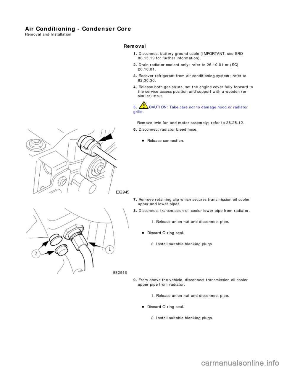
Air Conditioning - Condenser Core
Removal and Installation
Removal
1. Disconnect battery ground cable (IMPORTANT, see SRO
86.15.19 for further information).
2. Drain radiator coolant only; refer to 26.10.01 or (SC)
26.10.01.
3. Recover refrigerant from air co nditioning system; refer to
82.30.30.
4. Release both gas struts, set the engine cover fully forward to
the service access position an d support with a wooden (or
similar) strut.
5. CAUTION: Take care not to damage hood or radiator
grille.
Remove twin fan and motor as sembly; refer to 26.25.12.
6. Disconnect radiator bleed hose.
Release connection.
7. Remove retaining clip which secures transmission oil cooler
upper and lower pipes.
8. Disconnect transmission oil cooler lower pipe from radiator.
1. Release union nut and disconne ct pipe.
Discard O-ring seal.
2. Install suitable blanking plugs.
9. From above the vehicle, discon nect transmission oil cooler
upper pipe from radiator.
1. Release union nut and disconne ct pipe.
Discard O-ring seal.
2. Install suitable blanking plugs.
Page 1815 of 2490
15. Remove the temporary wooden support strut and reconnect
gas struts to the hood.
16. Check transmission fluid level an d top up as required; refer to
307A-01 (N/A) or 307B-01 (S/C), operation 44.24.02.
17. Refill the cooling system; refer to 26.10.01 or (SC) 26.10.01.
18. Recharge air conditioning system; refer to 82.30.30.
19. Reconnect battery ground cable (IMPORTANT, see SRO
86.15.15 for further information).
Page 1816 of 2490
Air Conditioning - Evaporator Core
Removal and Installation
Removal
1. Remove heater / cooler unit; refer to 82.25.21.
2. Remove air conditioning control module from heater / cooler
unit.
Slacken upper fixing.
Remove lower fixings.
3. Remove evaporator pipe firewall seal plate.
Remove screws.
Remove plate.
4. Disconnect heater matrix temperature sensor.
Detach heater matrix temperature sensor connector from
unit.
Disconnect connector.
5. Remove footwell servo motor from heater / cooler unit.
Disconnect connector.
Remove screws.
Remove motor complete with bracket.
6. Disconnect evaporator sensor connector.
Page 1818 of 2490
Air Conditioning - Pressure Cutoff Switch
Removal and Installation
Removal
Installation
1. Remove pressure switch.
Disconnect connector.
• NOTE: Discard O-ring seal.
Remove switch.
1. NOTE: Clean mating faces, instal l new O-ring seal and lubricate with clean compressor oil.
Installation is a reversal of the removal procedure.
Page 1819 of 2490
Air Conditioning - Receiver Drier
Removal and Installation
Removal
Installation
1. Disconnect battery ground cable (IMPORTANT, see SRO
86.15.19 for further information).
2. Remove air cleaner assemb ly; refer to 19.10.05.
3. Recover refrigerant from air co nditioning system; refer to
82.30.30.
4. Disconnect receiver / drier to evaporator line from receiver /
drier bottle.
Remove bolt.
Disconnect hose and discard O-ring seal.
Install suitable blanking plugs.
5. Disconnect condenser to receiver / drier line from receiver /
drier bottle.
Remove bolt.
Disconnect hose and discard O-ring seal.
Install suitable blanking plugs.
6. Remove drier bottle assembly.
Remove bolts.
Remove assembly.
Remove mounting rubbers.
1. NOTE: Install new O-ring seals and lubricate with clean
compressor oil.
Installation is reverse of removal procedure.
2. Tighten fixings to specification (8-10 Nm).