1998 JAGUAR X308 warning light
[x] Cancel search: warning lightPage 1081 of 2490
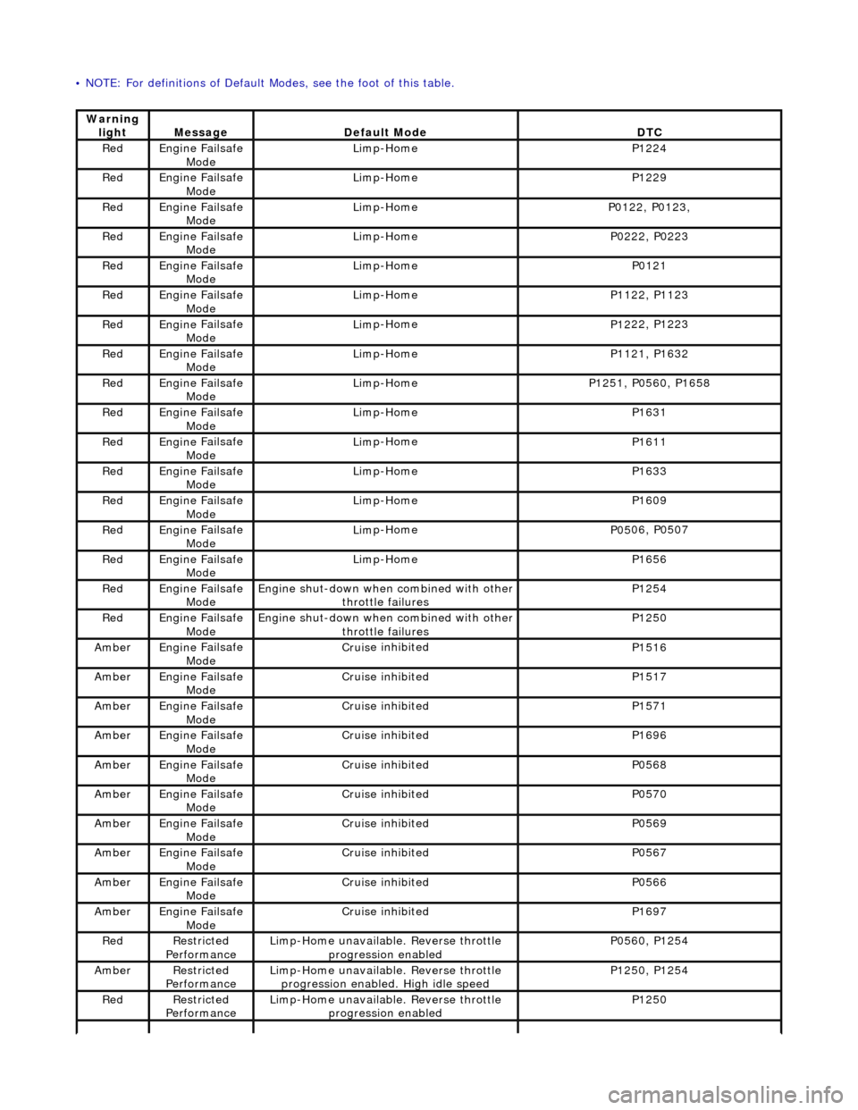
•
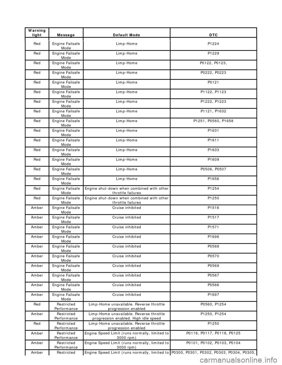
NOTE: For definitions of Default Modes, see the foot of this table.
Warning
lightMess
age
De
fault Mode
DT
C
Re
d
Engine
Failsafe
Mode
Lim
p-Home
P1224
Re
d
Engine
Failsafe
Mode
Lim
p-Home
P1229
Re
d
Engine
Failsafe
Mode
Lim
p-Home
P01
22, P0123,
Re
d
Engine
Failsafe
Mode
Lim
p-Home
P02
22, P0223
Re
d
Engine
Failsafe
Mode
Lim
p-Home
P0121
Re
d
Engine
Failsafe
Mode
Lim
p-Home
P11
22, P1123
Re
d
Engine
Failsafe
Mode
Lim
p-Home
P12
22, P1223
Re
d
Engine
Failsafe
Mode
Lim
p-Home
P11
21, P1632
Re
d
Engine
Failsafe
Mode
Lim
p-Home
P12
51, P0560, P1658
Re
d
Engine
Failsafe
Mode
Lim
p-Home
P1631
Re
d
Engine
Failsafe
Mode
Lim
p-Home
P1611
Re
d
Engine
Failsafe
Mode
Lim
p-Home
P1633
Re
d
Engine
Failsafe
Mode
Lim
p-Home
P1609
Re
d
Engine
Failsafe
Mode
Lim
p-Home
P05
06, P0507
Re
d
Engine
Failsafe
Mode
Lim
p-Home
P1656
Re
d
Engine
Failsafe
Mode
Engine
shut-down when combined with other
throttle failures
P1254
Re
d
Engine
Failsafe
Mode
Engine
shut-down when combined with other
throttle failures
P1250
Ambe
r
Engine
Failsafe
Mode
Cruis
e inhibited
P1516
Ambe
r
Engine
Failsafe
Mode
Cruis
e inhibited
P1517
Ambe
r
Engine
Failsafe
Mode
Cruis
e inhibited
P1571
Ambe
r
Engine
Failsafe
Mode
Cruis
e inhibited
P1696
Ambe
r
Engine
Failsafe
Mode
Cruis
e inhibited
P0568
Ambe
r
Engine
Failsafe
Mode
Cruis
e inhibited
P0570
Ambe
r
Engine
Failsafe
Mode
Cruis
e inhibited
P0569
Ambe
r
Engine
Failsafe
Mode
Cruis
e inhibited
P0567
Ambe
r
Engine
Failsafe
Mode
Cruis
e inhibited
P0566
Ambe
r
Engine
Failsafe
Mode
Cruis
e inhibited
P1697
Re
d
Re
stricted
Performance
Li
mp-Home unavailable. Reverse throttle
progression enabled
P05
60, P1254
Ambe
r
Re
stricted
Performance
Li
mp-Home unavailable. Reverse throttle
progression enabled. High idle speed
P12
50, P1254
Re
d
Re
stricted
Performance
Li
mp-Home unavailable. Reverse throttle
progression enabled
P1250
Page 1110 of 2490
2.2. Cruise
3. 3. Mechanica l
guard
4. 4. Fixed idle
5. 5. Redundancy
6. 6. Full authority
7. 7. Engine shut-down
Normal mode occurs when the EC M uses the mechanical and monitoring arrangem ent of the throttle valve to control throttle
opening. The ECM does not permit driver demand to be exceeded but it can be restricted to allow for such features as
stability / traction control, or engine power limitation.
The ECM determines engine idle speed by controlling the throttle valve motor to vary the blade angle between the non-
adjustable preset limits of the mechanic al guard and the throttle valve motor.
Cruise mode is engaged as a result of the ECM calculating and controlling the required throttle valve opening via the
vacuum system. When the driver releases the throttle pedal, the input shaft disengages from the mechanical guard or the
vacuum actuator pulls the guard away from th e throttle valve. The throttle pedal will feel light should it be pushed again to
accelerate (pressing the pedal further will re-engage the input shaft with the mechanical guard and restore normal feel).
The ECM utilizes sensors to monitor the relative positions of the mechanical guard and throttle valve and adjusts them to
maintain the set cruise speed.
Mechanical guard mode permits full mechanical operation of the throttle if the ECM detects that a problem has been
encountered with the throttle valve position sensor, dc motor, associated harnesses / connecto rs or the ECM.
Fixed idle mode occurs when any two of the three sensors (two input shaft sensors and the mechanical guard sensor) fail.
The ECM will assume values which represent a blade angl e of approximately 2,5° and 1200 rpm (unloaded) maximum
engine speed.
Redundancy mode occurs when any one of the three sensors (two input shaft sensors and the mechanical guard sensor)
fails. The operational pair will be deemed to be safe to co ntinue without intervention, but cruise will be inhibited.
Full authority mode is invoked when a mech anical guard failure occurs which indicates that the guard is stuck fully open.
The red warning lamp will be lit and road speed will be li mited to 120 kph.
Engine shut-down mode will occur followin g multiple failures, such as mechanical guard mode following full authority mode
(or vice versa) or the throttle blade sticks.
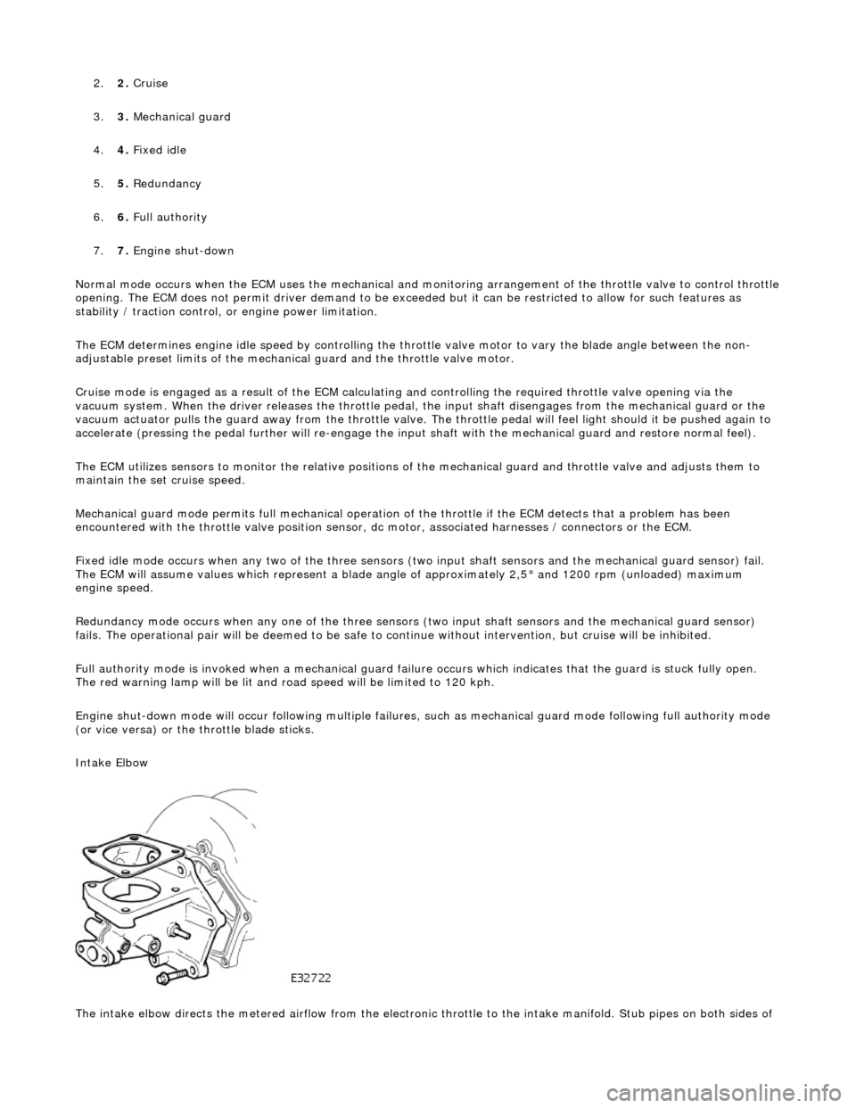
Intake Elbow
The intake elbow directs the metered airflow from the electronic throttle to the intake manifold. Stub pipes on both sides of
Page 1173 of 2490
Evapor
ative Emissions - Fuel Va
por Vent Valve Housing Seal
Remov
al and Installation
Re
moval
• NO
TE: The Removal and Installation procedur
es below show one type of flange but are applicable to the other evaporative loss systems
described.
Special To
ol(s)
Lock
Ring Wrench - Fuel Tank Flange
412-070 (JD 174)
1. Remove battery. Refer to 86.15.01.
2. WARNING: BEFORE PROCEEDING, IT IS ESSENTIAL THAT THE
WARNING NOTES GIVEN IN SECTIO N 100-00 (UNDER THE HEADING
'SAFETY PRECAUTIONS') ARE READ AND UNDERSTOOD.
Remove fuel tank assembly for access. Refer to operation 19.55.01.
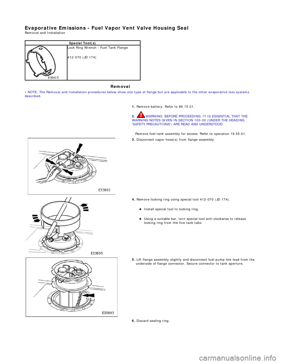
3. Discon
nect vapor hose(s) from flange assembly.
4. Remov
e locking ring using special tool 412-070 (JD 174).
Insta
ll special tool to locking ring.
Usi
ng a suitable bar, turn special tool anti-clockwise to release
locking ring from the five tank tabs.
5. Lift
flange assembly slightly and disconnect fuel pump link lead from the
underside of flange connector. Secure connector to tank aperture.
6. Discard sealing ring.
Page 1189 of 2490
E
lectronic Engine Controls -
Electronic Engine Controls
D
iagnosis and Testing
I
nspection and Verification
1.
1. Veri
fy the customer concern.
2. 2. Confirm which, if any, warning li ghts and/or messages were displayed on the instrument cluster.
• NOTE: If any warning lights and/or me ssages were displayed when the fault occurred, refer to the Driver Information
table for DTCs associated with the display, then to the DTC index table for possible sources and actions. Some warnings will
appear to clear when the ignition is cycl ed. This is often because the warning has flagged as a resu lt of one of the vehicle's
on-board diagnostic routines having run to detect the fault. If the same routine is not run when the ignition is switched ON,
the warning will not reflag until the routine does run. See the DTC summaries for drive cycle routines.
3. 3. Visually inspect for obvious signs of mechanical or electrical damage.
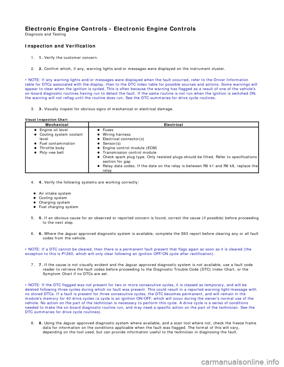
V
isual Inspection Chart
4.
4. Veri
fy the following syst
ems are working correctly:
Air in
take system
Coo
ling system
Charging system
F
uel charging system
5. 5. If an obvious cause for an observed or reported concern is found, correct the cause (if possible) before proceeding
to the next step.
6. 6. Where the Jaguar approved diagnostic sy stem is available, complete the S93 report before clearing any or all fault
codes from the vehicle.
• NOTE: If a DTC cannot be cleared, then there is a permanent fault present that flag s again as soon as it is cleared (the
exception to this is P1260, which will only clear following an ignition OFF/ON cycle after rectification).
7. 7. If the cause is not visually evident and the Jaguar approv ed diagnostic system is not available, use a fault code
reader to retrieve the fault codes be fore proceeding to the Diagnostic Trou ble Code (DTC) Index Chart, or the
Symptom Chart if no DTCs are set.
• NOTE: If the DTC flagged was not present for two or more co nsecutive cycles, it is classed as temporary, and will be
deleted following three cycl es during which no fault was present. This could result in a reported wa rning light/message with
no stored DTCs. If a fault is present for three consecutive cycles, the DTC becomes permanent, and will remain in the
module's memory for 40 drive cycles (a cy cle is an ignition ON/OFF, which will occur during the owner's normal use of the
vehicle. No action on the part of the technician is necessary to perform this cycle. A drive cycle is a series of conditions
needed to make the on-board diagnostic ro utine run, and may need a specific action on the part of the technician. See the
DTC summaries for driv e cycle routines).
8. 8. Using the Jaguar approved diagnostic system where available, and a scan tool where not, check the freeze frame
data for information on the conditions applicable when the fault was flagged. The format of this will vary,
dependin
g o
n the tool used, but can provide information useful to the technician in dia
gnos
in
g th
e fault.
MechanicalElectrical
Engi
ne oil level
Coo
ling system coolant
level
Fuel contamination
Throttle body Poly
-vee belt
F
uses
W
iring harness
E
lectrical connector(s)
Sens
or(s)
Engine
control module (ECM)
Tran
smission control module
Check spark plu
g type. Only re
sisted plugs should be fitted. Refer to specifications
section for gap
Relay date codes.
If the date on the rela
y is between R6 k1 and R6 k8, replace the
relay
Page 1193 of 2490
Re
d
Engine
Failsafe
Mode
Lim
p-Home
P1224
Re
d
Engine
Failsafe
Mode
Lim
p-Home
P1229
Re
d
Engine
Failsafe
Mode
Lim
p-Home
P01
22, P0123,
Re
d
Engine
Failsafe
Mode
Lim
p-Home
P02
22, P0223
Re
d
Engine
Failsafe
Mode
Lim
p-Home
P0121
Re
d
Engine
Failsafe
Mode
Lim
p-Home
P11
22, P1123
Re
d
Engine
Failsafe
Mode
Lim
p-Home
P12
22, P1223
Re
d
Engine
Failsafe
Mode
Lim
p-Home
P11
21, P1632
Re
d
Engine
Failsafe
Mode
Lim
p-Home
P12
51, P0560, P1658
Re
d
Engine
Failsafe
Mode
Lim
p-Home
P1631
Re
d
Engine
Failsafe
Mode
Lim
p-Home
P1611
Re
d
Engine
Failsafe
Mode
Lim
p-Home
P1633
Re
d
Engine
Failsafe
Mode
Lim
p-Home
P1609
Re
d
Engine
Failsafe
Mode
Lim
p-Home
P05
06, P0507
Re
d
Engine
Failsafe
Mode
Lim
p-Home
P1656
Re
d
Engine
Failsafe
Mode
Engine
shut-down when combined with other
throttle failures
P1254
Re
d
Engine
Failsafe
Mode
Engine
shut-down when combined with other
throttle failures
P1250
Ambe
r
Engine
Failsafe
Mode
Cruis
e inhibited
P1516
Ambe
r
Engine
Failsafe
Mode
Cruis
e inhibited
P1517
Ambe
r
Engine
Failsafe
Mode
Cruis
e inhibited
P1571
Ambe
r
Engine
Failsafe
Mode
Cruis
e inhibited
P1696
Ambe
r
Engine
Failsafe
Mode
Cruis
e inhibited
P0568
Ambe
r
Engine
Failsafe
Mode
Cruis
e inhibited
P0570
Ambe
r
Engine
Failsafe
Mode
Cruis
e inhibited
P0569
Ambe
r
Engine
Failsafe
Mode
Cruis
e inhibited
P0567
Ambe
r
Engine
Failsafe
Mode
Cruis
e inhibited
P0566
Ambe
r
Engine
Failsafe
Mode
Cruis
e inhibited
P1697
Re
d
Re
stricted
Performance
Li
mp-Home unavailable. Reverse throttle
progression enabled
P05
60, P1254
Ambe
r
Re
stricted
Performance
Li
mp-Home unavailable. Reverse throttle
progression enabled. High idle speed
P12
50, P1254
Re
d
Re
stricted
Performance
Li
mp-Home unavailable. Reverse throttle
progression enabled
P1250
Ambe
r
Re
stricted
Performance
Engine
Speed Limit (runs normally, limited to
3000 rpm)
P01
16, P0117, P0118, P0125
Ambe
r
Re
stricted
Performance
Engine
Speed Limit (runs normally, limited to
3000 rpm)
P01
01, P0102, P0103, P0104
Ambe
r
Re
stricted
Engine
Speed Limit (runs normally, limited to
P03
00, P0301, P0302, P0303, P0304, P0305,
Warning
lightMess
age
De
fault Mode
DT
C
Page 1734 of 2490
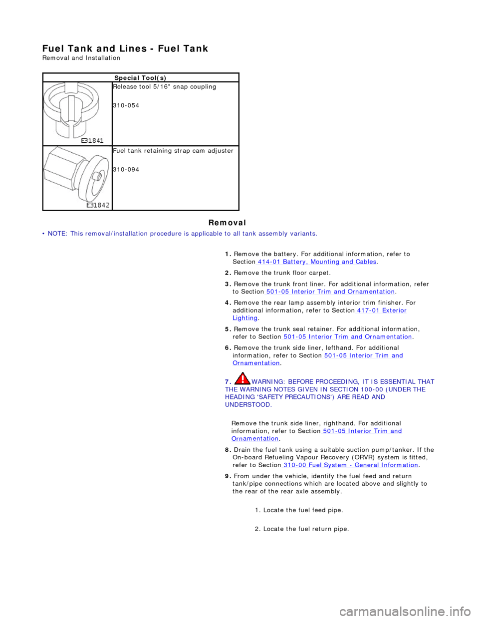
Fuel Tank and Lines - Fuel Tank
Re
mo
val and Installation
Remov
a
l
•
NO
TE: This removal/installation procedure is applicable to all tank assembly variants.
S
p
ecial Tool(s)
R
e
lease tool 5/16" snap coupling
310-054
F u
el tank retaining strap cam adjuster
310-094
1. Remove the battery. For additi onal information, refer to
Section 414
-01
Battery, Mounting and Cables
.
2. Re
move the trunk floor carpet.
3. Remove the trunk front liner. Fo r additional information, refer
to Section 501
-05
Interior Trim and Ornamentation
.
4. Re
move the rear lamp assembly interior trim finisher. For
additional information, refer to Section 417
-01
Exterior
Ligh
ting.
5. Re
move the trunk seal retainer
. For additional information,
refer to Section 501
-0 5
Interior Trim and Ornamentation
.
6. Re
move the trunk side liner, lefthand. For additional
information, refer to Section 501
-05
Interior Trim and
Or
n
amentation
.
7. WARNING: B E
FORE PROCEEDING, IT IS ESSENTIAL THAT
THE WARNING NOTES GIVEN IN SECTION 100-00 (UNDER THE
HEADING 'SAFETY PRECAUTIONS') ARE READ AND
UNDERSTOOD.
Remove the trunk side liner, righthand. For additional
information, refer to Section 501
-05
Interior Trim and
Or
n
amentation
.
8.
Drain th e fue
l tank using a suitab
le suction pump/tanker. If the
On-board Refueling Vapour Recove ry (ORVR) system is fitted,
refer to Section 310
-00 Fu
el System
- General
Information
.
9. Fr
om under the vehicle, identify the fuel feed and return
tank/pipe connections which are located above and slightly to
the rear of the rear axle assembly.
1. Locate the fuel feed pipe.
2. Locate the fuel return pipe.
Page 1977 of 2490
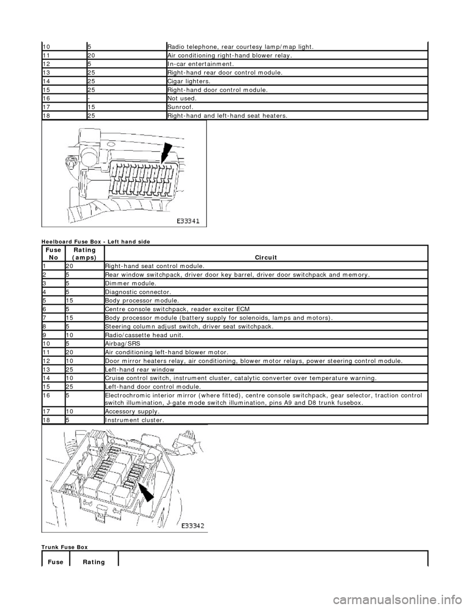
Heelboard Fuse Box - Left hand side
Trunk Fuse Box
105Radio telephone, rear courtesy lamp/map light.
1120Air conditioning right-hand blower relay.
125In-car entertainment.
1325Right-hand rear door control module.
1425Cigar lighters.
1525Right-hand door control module.
16-Not used.
1715Sunroof.
1825Right-hand and left-hand seat heaters.
Fuse NoRating
(amps)Circuit
120Right-hand seat control module.
25Rear window switchpack, driver door key ba rrel, driver door switchpack and memory.
35Dimmer module.
45Diagnostic connector.
515Body processor module.
65Centre console switchpack, reader exciter ECM
715Body processor module (battery supply for solenoids, lamps and motors).
85Steering column adjust switch, driver seat switchpack.
910Radio/cassette head unit.
105Airbag/SRS
1120Air conditioning left-hand blower motor.
1210Door mirror heaters relay, air conditioning, blow er motor relays, power steering control module.
1325Left-hand rear window
1410Cruise control switch, instrument cluster, catalytic converter over temperature warning.
1525Left-hand door control module.
165Electrochromic interior mirror (where fitted), centre console switchpack, gear selector, traction control
switch illumination, J-gate mode switch illumination, pins A9 and D8 trunk fusebox.
1710Accessory supply.
185Instrument cluster.
Fuse Rating
Page 2007 of 2490
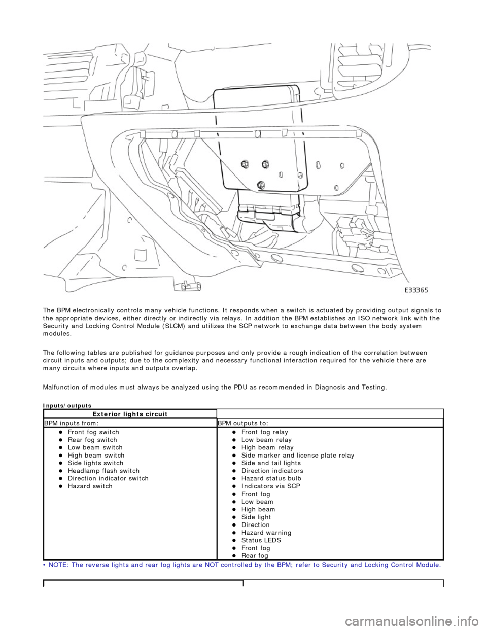
The BPM electronically controls many vehicle functions. It responds when a switch is actuated by providing output signals to
the appropriate devices, either di rectly or indirectly via relays. In addition the BPM establishes an ISO network link with the
Security and Locking Control Module (SLC M) and utilizes the SCP network to exchange data between the body system
modules.
The following tables are publis hed for guidance purposes and only provide a rough indication of the correlation between
circuit inputs and outputs; due to the complexity and necess ary functional interaction required for the vehicle there are
many circuits where inpu ts and outputs overlap.
Malfunction of modules must always be analyzed using the PDU as recommended in Diagnosis and Testing.
Inputs/outputs
• NOTE: The reverse lights and rear fog lights are NOT controlled by the BPM; refer to Security and Locking Control Module.
Exterior lights circuit
BPM inputs from: BPM outputs to:
Front fog switch Rear fog switch Low beam switch High beam switch Side lights switch Headlamp flash switch Direction indicator switch Hazard switch
Front fog relay Low beam relay High beam relay Side marker and license plate relay Side and tail lights Direction indicators Hazard status bulb Indicators via SCP Front fog Low beam High beam Side light Direction Hazard warning Status LEDS Front fog Rear fog