1998 JAGUAR X308 warning light
[x] Cancel search: warning lightPage 2008 of 2490
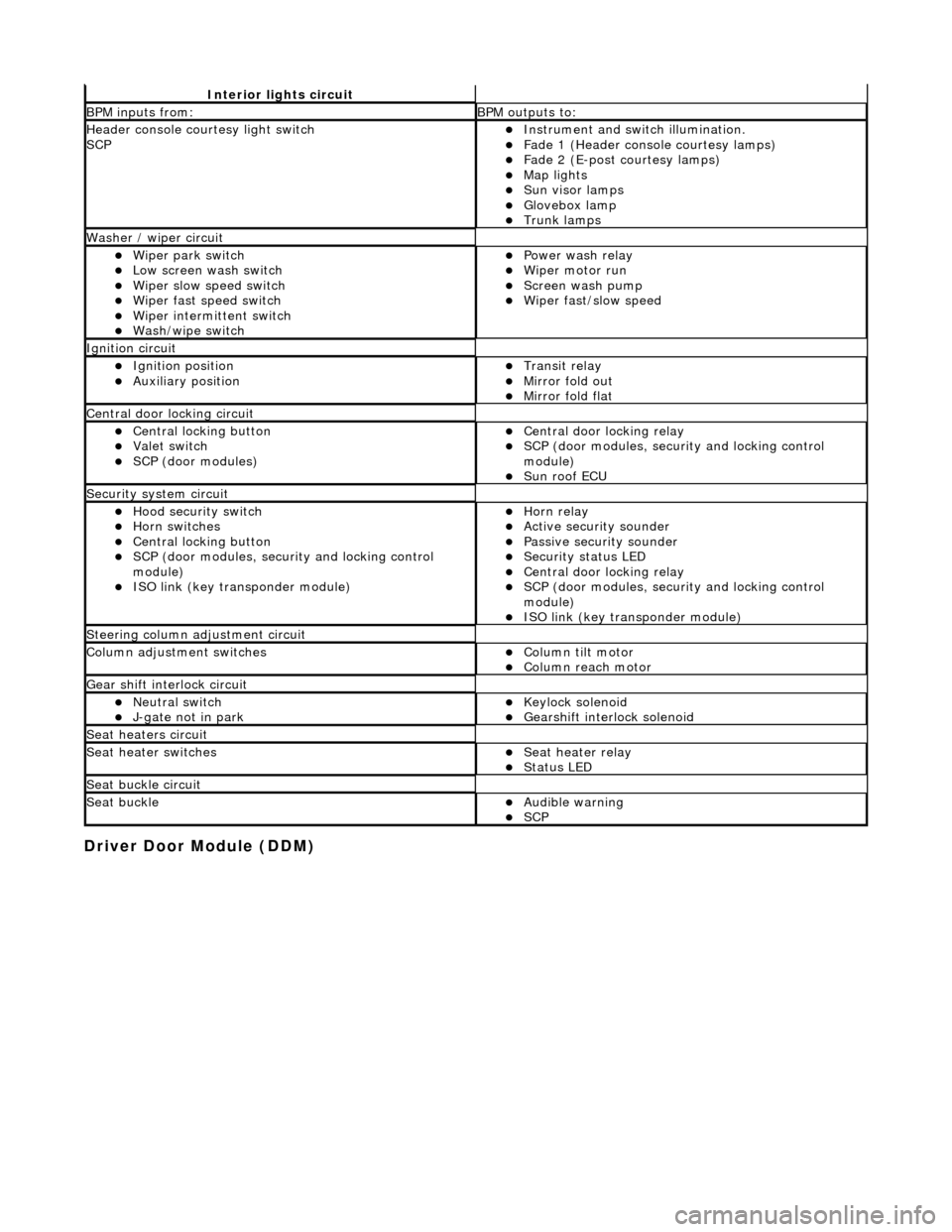
Driver Door Module (DDM)
Interior lights circuit
BPM inputs from: BPM outputs to:
Header console courtesy light switch
SCPInstrument and switch illumination. Fade 1 (Header console courtesy lamps) Fade 2 (E-post courtesy lamps) Map lights Sun visor lamps Glovebox lamp Trunk lamps
Washer / wiper circuit
Wiper park switch Low screen wash switch Wiper slow speed switch Wiper fast speed switch Wiper intermittent switch Wash/wipe switch
Power wash relay Wiper motor run Screen wash pump Wiper fast/slow speed
Ignition circuit
Ignition position Auxiliary position Transit relay Mirror fold out Mirror fold flat
Central door locking circuit
Central locking button Valet switch SCP (door modules)
Central door locking relay SCP (door modules, security and locking control
module)
Sun roof ECU
Security system circuit
Hood security switch Horn switches Central locking button SCP (door modules, security and locking control
module)
ISO link (key transponder module)
Horn relay Active security sounder Passive security sounder Security status LED Central door locking relay SCP (door modules, security and locking control
module)
ISO link (key transponder module)
Steering column adjustment circuit
Column adjustment switchesColumn tilt motor Column reach motor
Gear shift interlock circuit
Neutral switch J-gate not in park Keylock solenoid Gearshift interlock solenoid
Seat heaters circuit
Seat heater switchesSeat heater relay Status LED
Seat buckle circuit
Seat buckleAudible warning SCP
Page 2022 of 2490
Body closures
Each front and rear door consists of a welded, mild steel inner frame and an outer panel. The outer panel is welded to the
waist rail and cheater of the inner frame, then bonded and clinched to fo rm the door assembly. Cosmetic PVC bead is
applied to all clinch joints. Sp onge rubber seals are mounted on the doors. Inte rnal insulation is provided by a foam water
shedder attached to the door by double-sided adhesive tape.
The door aperture B/C posts are reinforced over their full height to fully satisfy all forthcoming European and Federal side
impact legislation. The hood consists of one piece inner and outer panels clinched and bonded together, with cosmetic bead
PVC sealant applied to all clinch joints. Th e hood pivots at the front on two hinges each secured by bolts to the hood front
underside and the BIW front upper crossmem ber. Two gas struts secured to the hood by pivot pins and snap-on couplings,
support the hood in the open position. A full width insulating pad is secured by screws to the underside of the hood. A
sponge rubber tubular seal is mounted tran sversely towards the front of the hood underside. The trunk lid is of similar
construction to the hood, consisting of inner and outer pa nels clinched and bonded together and PVC bead sealed.
Incorporating a removable moulded liner and two trunk illuminati on lights, the trunk lid is supported when open, by two gas
struts, each secured to the inner wheel arch and trunk hinge by snap fittin gs. For some markets, a warning triangle is
attached to a bracket on the trunk lid underside and is retained in the open position by a rubber block.
Fascia
One-piece slush-moulded fascia on inject ion moulded armature and steel cross-rail reinforcement. Fascia support brackets
set with BIW to achieve close tolerance fit of fascia to bo dy eliminate necessity for adjustment following removal and
installation..
Fuel Filler Flap
The fuel filler comprising a hinged flap attached to the body decking panel by tw o nuts, incorporates a rubber buffer, snap-
in striker, hinge spring and fuel cap stowage magnet. The rubber fuel bowl moulding is attached via a steel armature to the
body reinforcement panel by five M5 nuts and is retained at the filler neck by a clip. The mating drain tube is fitted with an
internal filter. The fuel filler flap latch mechanism attached to the fuel bowl armatu re by two M5 nuts, includes a locking pin
and actuator which are both se rviceable items. The latch actuator operates independently from the central locking system;
it is driven directly by the se curity and locking control module. Locking of the fuel filler flap is achi eved only by operation of
the key or by the remote rf transmitter.
Seating
All front seats are equipped with electric height adjustment. In addition, both seats are available with manual or power
forward and rearward adjustment, manual or power operated headrest adjustment, 12 way electric adjustment, memory
controlled 12 way seat adjustment and integral seat heating. A side air bag module is installe d in the outboard squab wing
of each front seat. Each front seat has a non-handed, one-piece frame incorporatin g cushion and squab frames, side air bag
support bracket and seat adjuster mechanis ms. Seat switchpacks are installed on the outboard side of driver and passenger
seats and control modules are installed in the base of each seat . The standard rear seat is of fixed, bench type with full
width removable cushion. For certain mark ets, two individual rear seats are available as an option on long wheelbase
models. Both type s of rear seat are available with th ermostatically controlled heating of the cushion and sq uab. Individual
rear seats are electrically adjustable fo r squab re cline (via cushion fore and af t movement), head restraint height and
lumbar support. Separate motors provide ad justment of each seat cushion and head restraint and an electrically driven air
compressor provides variation of lumbar support. Seat adjustment is controlled via switches installed on a panel in an
extension to the centre console.Both the driver and front pass enger seat are secured to the vehicle floor at four points.
Interior Trim
The one-piece door casings are trimmed in UEV to match the seating, with wood veneer at the waistline and a carpet insert
at the front lower corner. Each casing is secured to the door inner panel by fir tree fastener s along the lower section, two
armrest fixings at the centre and veneer panel dowels and fixings at the top. The armrests which are common to front and
rear doors, are trimmed in matc hing leather or UEV according to specification. Switchpacks dedicated to driver and front or
rear passenger, are incorporated in the ar mrests. A speaker is installed in the lower section of each door and a tweeter is
incorporated behind each interior door handle escutcheon. where premium ICE is fitted, the front tweeters are installed in
the upper A posts. On each side, a graine d UEV finisher trimmed to match the head lining is secured to the 'A' post and
cantrail by fir tree fasteners locating in BIW apertures. Th e upper 'D' post finisher is trimmed and secured in the same
manner. The single piece'B' post finishers, also finished in grained matching UEV, each have a front seat belt exit aperture
and are secured to the BIW by four spring clips and two fir tree fasteners. The one-piece headlining consists of a 6mm thick
polyurethane foam membrane covered with suede effect knitted polyester. The headlining is secured to the BIW roof by
body tangs, the roof console, sun visors, combined grab handles and coat hooks, th e cantrail finishers and where fitted, the
Page 2035 of 2490
the BIW front upper crossmember. Two gas struts secured to the hood by pi vot pins and snap-on couplings, support the
hood in the open position. A full width insulating pad is secured by screws to the underside of the hood. A sponge rubber
tubular seal is mounted transversely to wards the front of the hood underside.
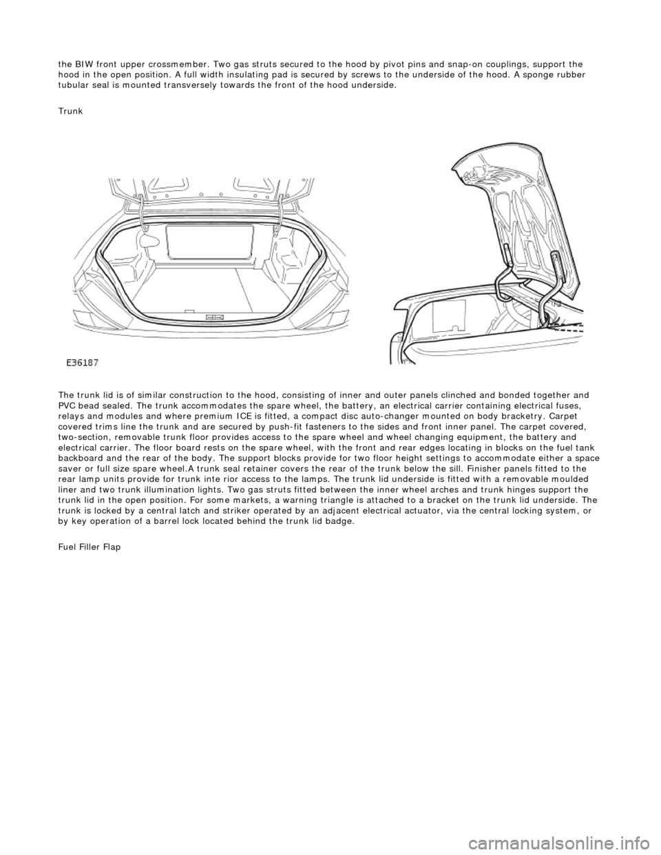
Trunk
The trunk lid is of similar construction to the hood, consisting of inner and outer panels clinched and bonded together and
PVC bead sealed. The trunk accommodates the spare wheel, the battery, an electrical carrier containing electrical fuses,
relays and modules and where premium ICE is fitted, a compac t disc auto-changer mounted on body bracketry. Carpet
covered trims line the trunk and are secured by push-fit fasten ers to the sides and front inner panel. The carpet covered,
two-section, removable trunk floor prov ides access to the spare wheel and wheel changing equipment, the battery and
electrical carrier. The floor board rests on the spare wheel, with the front and rear e dges locating in blocks on the fuel tank
backboard and the rear of the body. The support blocks provide for two floor height settings to accommodate either a space
saver or full size spare wheel.A trunk seal retainer covers the re ar of the trunk below the sill. Finisher panels fitted to the
rear lamp units provide for trunk inte rior access to the lamps. The trunk lid underside is fitted with a removable moulded
liner and two trunk illumination lights. Two gas struts fitted between the inner wheel arches and trunk hinges support the
trunk lid in the open position. For some markets, a warning triangle is attached to a bracket on the trunk lid underside. The
trunk is locked by a central latch and stri ker operated by an adjacent electrical actuator, via the central locking system, or
by key operation of a barrel lock located behind the trunk lid badge.
Fuel Filler Flap
Page 2351 of 2490
Installation
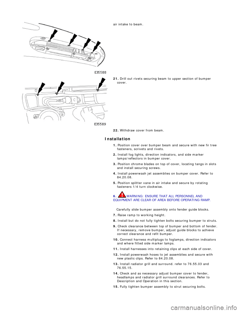
air intake to beam.
21. Drill out rivets securing beam to upper section of bumper
cover.
22. Withdraw cover from beam.
1. Position cover over bumper beam and secure with new fir tree
fasteners, scrivets and rivets.
2. Install fog lights, direction indicators, and side marker
lamps/reflectors in bumper cover.
3. Position chrome blades on top of cover, locating tangs in slots
and install securing screws.
4. Install powerwash jet assemblies on bumper cover. Refer to
84.20.08.
5. Position splitter vane in air intake and secure by rotating
fasteners 1/4 turn clockwise.
6. WARNING: ENSURE THAT ALL PERSONNEL AND
EQUIPMENT ARE CLEAR OF AREA BEFORE OPERATING RAMP.
Carefully slide bumper assembly onto fender guide blocks.
7. Raise ramp to working height.
8. Install but do not fully tighten bo lts securing bumper to struts.
9. Check clearance between top of bumper and bottom of fender.
If necessary, remove bumper, adjust guide blocks to achieve
correct clearance and refit bumper.
10. Connect harness multiplugs to foglamps, direction indicators
and where fitted side marker lamps.
11. Install harnesses into retaining clips at each side of cover.
12. Install powerwash hoses to jet assemblies and secure with
new plastic clips. Refer to 84.20.08.
13. Install radiator grill and su rround. refer to 76.55.03 and
76.55.15.
14. Check and as necessary adjust bumper cover to fender,
headlamps and radiator grill surround clearances. Refer to
Description and Operation in this section.
15. Fully tighten bumper assembly to strut securing bolts.
Page 2391 of 2490
ZINC COATED PANELS
Description
Approximately 70% of the 'body in white' (BIW) mass is made up of zinc coated panels.
• NOTE: To maintain the protective qualities of the zinc trea tment, repairs to any damaged coated area must be made as
soon as possible after the damage has occurred.
All exterior skin panels, with the exceptio n of the roof, are double side zinc plated and this coating (nominally 7,5 microns)
provides two way corrosion protection. Should the outer layer of paint become chipped with the zinc coating remain intact,
the zinc will oxidize on contact with air and being impermeable, this coat of oxidation will prevent corrosion damage of the
base metal. If the outer layer of paint and the zinc coating become damaged, the zinc rather than the base metal will react
with the air and 'sacrifice' itself to corrosion as a 'sacrificial anode'.
Welding Preparation
Contamination of the weld with resultant reduction in joint st rength increase and increased electrode tip dressing frequency
will occur zinc coating is not removed. In exceptional cases where the zinc coating must remain intact, the tip pressure and
welding current should be increased by 10 to 20%.
Where 'resistance spot welding' is employed, the zinc coatin g should be lightly abraded away on the mating surfaces and
those in contact with the electrode tips. Do not remove more zinc coating than is absolutely necessary.
Before welding, a weld-through primer or inter-weld sealer should be applied, as detailed in the Body Sealing and
Preservation manual.
Where MIG welding is used as an alternativ e to resistance spot welding for plug and butt welds or due to limited access, the
problems caused by the presence of zinc coating are much the same, with the added complication of increased weld spatter
and nozzle contamination.
Body Fillers
Conventional polyester fillers do not adhere satisfactorily to zinc plated panels, it is ther efore important that only those
products specifically designed for this application are used and the manufacturer's recommendations are followed.
Refinishing
Use only those products approved by Jaguar Cars Ltd and exercise special care on zinc coated panels.
As replacement panels ar e supplied ready primed, the only bare metal that needs to be exposed are those areas prepared
for welding etc, as decribed in 'Welding Preparation. Where any part of a panel is dressed back to the bare surface, it should
be treated with a zinc rich primer compatible with the paint application system.
GENERAL PREPARATION OF PANELS
Removal of Panels and Welds
• NOTE: Where other components must be removed for access, refer to the relevant manual section for guidance. This is
particularly important where steerin g, braking, suspension, electrical and safety systems are affected.
Expose all resistance spot welds, using a ro tary wire brush fitted to an air drill or a hand held wire brush on those that are
not clearly visible (1).
WARNING: DO NOT BURN UNDERSEAL OFF. USE A 'HOT KNIFE' OR SUITABLE SOLVENT.
Cut out spot welds using a Zipcutter or Roto-Bor (2). At this point it may be necessary to cut out the bulk of the panel using
Page 2392 of 2490
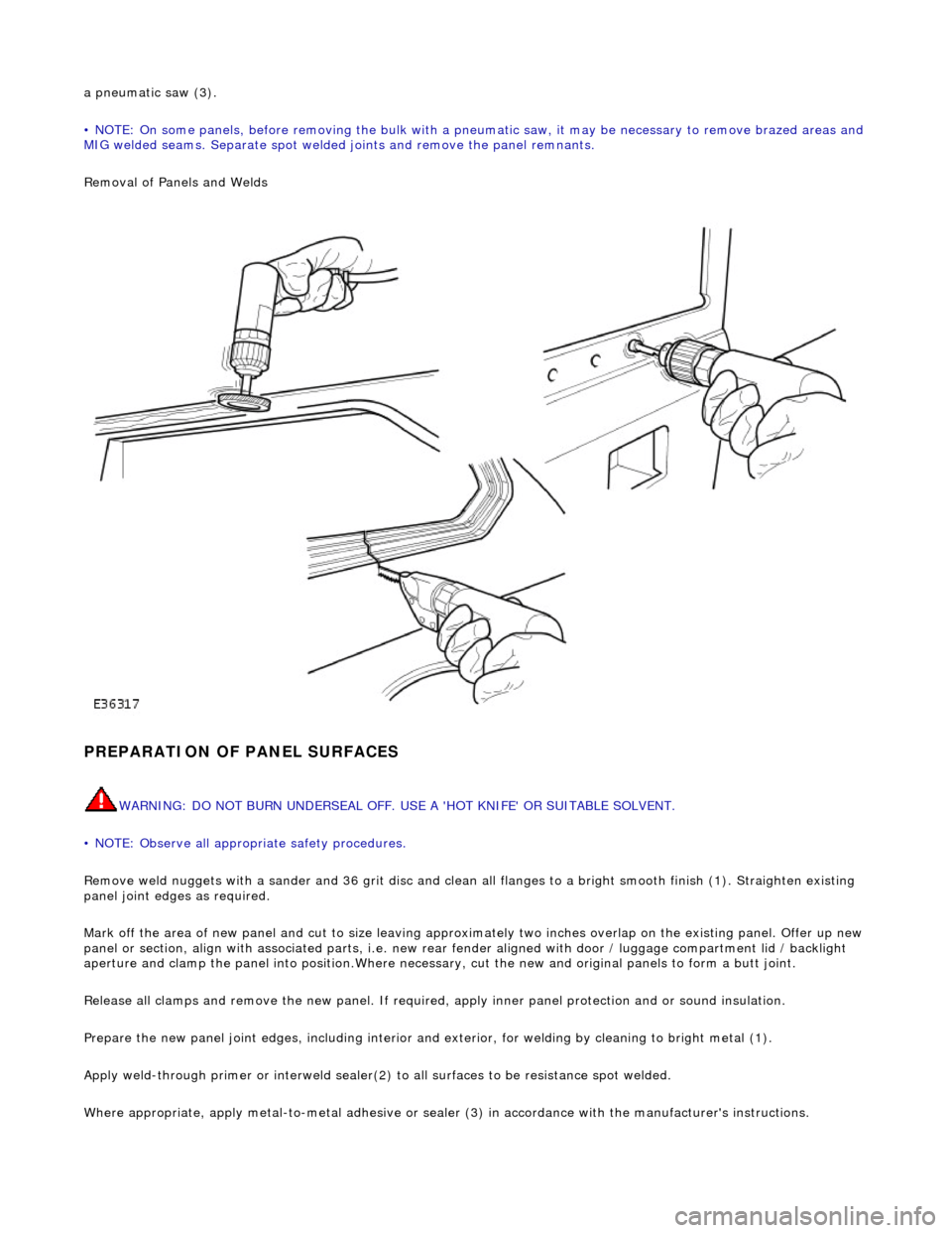
a pneumatic saw (3).
• NOTE: On some panels, before removing the bulk with a pneumatic saw, it may be necessary to remove brazed areas and
MIG welded seams. Separate spot welded joints and remove the panel remnants.
Removal of Panels and Welds
PREPARATION OF PANEL SURFACES
WARNING: DO NOT BURN UNDERSEAL OFF. USE A 'HOT KNIFE' OR SUITABLE SOLVENT.
• NOTE: Observe all appropriate safety procedures.
Remove weld nuggets with a sander and 36 gr it disc and clean all flanges to a bright smooth finish (1). Straighten existing
panel joint edges as required.
Mark off the area of new panel and cut to size leaving approxim ately two inches overlap on the existing panel. Offer up new
panel or section, align with associated pa rts, i.e. new rear fender aligned with door / luggage compartment lid / backlight
aperture and clamp the panel into positi on.Where necessary, cut the new and orig inal panels to form a butt joint.
Release all clamps and remove the new panel. If required, apply inner panel protection and or sound insulation.
Prepare the new panel joint edges, including interior and exterior, for welding by cleaning to bright metal (1).
Apply weld-through primer or in terweld sealer(2) to all surfaces to be resistance spot welded.
Where appropriate, apply metal- to-metal adhesive or sealer (3) in accordance with the manufacturer's instructions.