1998 JAGUAR X308 fuel pump
[x] Cancel search: fuel pumpPage 1031 of 2490
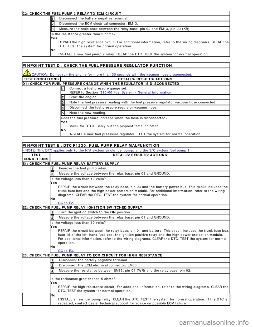
C2: CHECK THE FUEL
PUMP 2 RELAY TO ECM CIRCUIT
Di
sconnect the battery negative terminal.
1
D
isconnect the ECM electrical connector, EM13.
2
Meas
ure the resistance between the rela
y base, pin 02 and EM13, pin 09 (KB).
3
Is th
e resistance greater than 5 ohms?
Yes REPAIR the high resistance circuit. For additional information, refer to the wiring diagrams. CLEAR the
DTC. TEST the system for normal operation.
No INSTALL a new fuel pump 2 relay. CLEAR the DT C. TEST the system for normal operation.
P
INPOINT TEST D : CHECK THE FUEL PRESSURE REGULATOR FUNCTION
CAUTI
ON: Do not run the engine for more than
30 seconds with the vacuum hose disconnected.
T
EST CONDITIONS
D
ETAILS/RESULTS/ACTIONS
D
1: CHECK FOR FUEL PRESSURE CHANGE
WHEN THE REGULATOR IS DISCONNECTED
Connect a
fuel pressure gauge set,
REFER to Section 310
-00
Fuel System
-
General Informati
on
. 1
St
art the engine.
2
N
ote the fuel pressure readin
g with the fuel pressure regu lator vacuum hose connected.
3
Di
sconnect the fuel pressu
re regulator vacuum hose.
4
N
ote the new reading.
5
Doe
s the fuel pressure increase when the hose is disconnected?
Yes Check for DTCs. Carry out the pinpoint tests indicated.
No INSTALL a new fuel presssure regulator. TEST the system for normal operation.
P
INPOINT TEST E : DTC P1230;
FUEL PUMP RELAY MALFUNCTION
•
NOTE: This DTC applies only to the N/A system si
ngle fuel pump, and the S/C system fuel pump 1
TE
ST
CONDITIONS
D
ETAILS/RESULTS/ACTIONS
E1
: CHECK THE FUEL PUMP
RELAY BATTERY SUPPLY
R
emove the fuel pump relay.
1
Meas
ure the voltage between the
relay base, pin 03 and GROUND.
2
Is th
e voltage less than 10 volts?
Yes REPAIR the circuit between the rela y base, pin 03 and the battery power bus. This circuit includes the
trunk fuse box and the high power protection module . For additional information, refer to the wiring
diagrams. CLEAR the DTC. TEST th e system for normal operation.
No GO to E2
.
E2
: CHECK THE FUEL PUMP RELAY IGNITION SWITCHED SUPPLY
Turn the ignition swi
tch to the
ON position.
1
Meas
ure the voltage between the
relay base, pin 01 and GROUND.
2
Is th
e voltage less than 10 volts?
Yes REPAIR the circuit between the rela y base, pin 01 and battery. This circuit includes the trunk fuse box,
fuse 16 of the left-hand fuse box, the ignition po
sitive relay and the high power protection module.
For additional information, refer to the wiring diagrams. CLEAR the DTC. TEST the system for normal
operation.
No GO to E3
.
E3
: CHECK THE FUEL PUMP RELAY TO
ECM CIRCUIT FOR HIGH RESISTANCE
Di
sconnect the battery negative terminal.
1
D
isconnect the ECM electrical connector, EM83.
2
Meas
ure the resistance between EM83, pi
n 04 (WR) and the relay base, pin 02.
3
Is th
e resistance greater than 5 ohms?
Yes REPAIR the high resistance circuit. For additional information, refer to the wiring diagrams. CLEAR the
DTC. TEST the system for normal operation.
No
INSTALL a new fuel pump relay. CLEAR the DTC. TEST the system for normal operation. If the DTC is
repeated, contact dealer technical support for advice on possible ECM failure.
Page 1067 of 2490
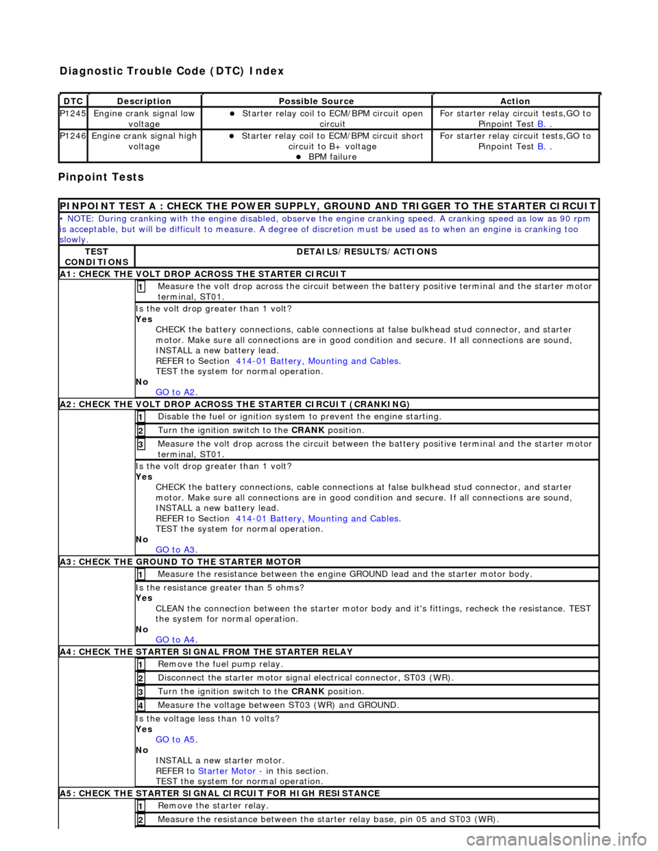
Pinpoint Tests
DT
C
De
scription
Possib
le Source
Acti
on
P1245Engine
crank signal low
voltage
Starter relay
coil to
ECM/BPM circuit open
circuit
F
or starter relay circuit tests,GO to
Pinpoint Test B.
.
P1246Engine
crank signal high
voltage
Starter relay
coil to ECM/BPM circuit short
circuit to B+ voltage
B
PM failure
F
or starter relay circuit tests,GO to
Pinpoint Test B.
.
P
INPOINT TEST A : CHECK THE
POWER SUPPLY, GROUND AND TRI GGER TO THE STARTER CIRCUIT
•
NOTE: During cranking with the engine disabled, observe the engine cranking speed. A cranking speed as low as 90 rpm
is acceptable, but will be difficult to measure. A degree of discretion must be used as to when an engine is cranking too
slowly.
TE
ST
CONDITIONS
D
ETAILS/RESULTS/ACTIONS
A1: CHECK
THE VOLT DROP AC
ROSS THE STARTER CIRCUIT
M
easure the volt drop across the circuit between the battery positive terminal and the starter motor
terminal, ST01.
1
Is the vol
t drop greater than 1 volt?
Yes CHECK the battery connections, cable connections at false bulkhead stud connector, and starter
motor. Make sure all connections are in good co ndition and secure. If all connections are sound,
INSTALL a new battery lead.
REFER to Section 414
-0
1 Battery, Mounting and Cables
.
TEST the system
for normal operation.
No GO to A2
.
A2: CHECK
THE VOLT DROP ACROSS
THE STARTER CIRCUIT (CRANKING)
Di
sable the fuel or ignition system to prevent the engine starting.
1
Turn the ignition swi
tch to the CRANK
position.
2
M
easure the volt drop across the circuit between the battery positive terminal and the starter motor
terminal, ST01.
3
Is the vol
t drop greater than 1 volt?
Yes CHECK the battery connections, cable connections at false bulkhead stud connector, and starter
motor. Make sure all connections are in good co ndition and secure. If all connections are sound,
INSTALL a new battery lead.
REFER to Section 414
-0
1 Battery, Mounting and Cables
.
TEST the system
for normal operation.
No GO to A3
.
A3:
CHECK THE GROUND TO THE STARTER MOTOR
Meas
ure the resistance between the engine GROUND lead and the starter motor body.
1
Is th
e resistance greater than 5 ohms?
Yes CLEAN the connection between the starter motor body and it's fittings, recheck the resistance. TEST
the system for normal operation.
No GO to A4
.
A4
: CHECK THE STARTER SIGNAL FROM THE STARTER RELAY
R
emove the fuel pump relay.
1
Di
sconnect the starter motor signal
electrical connector, ST03 (WR).
2
Turn the ignition swi
tch to the CRANK
position.
3
M
easure the voltage between ST03 (WR) and GROUND.
4
Is th
e voltage less than 10 volts?
Yes GO to A5
.
No
INSTALL a new starter motor.
REFER to Starter Motor
-
in t
his section.
TEST the system for normal operation.
A5
: CHECK THE STARTER SIGNAL CIRCUIT FOR HIGH RESISTANCE
R
emove the starter relay.
1
Meas
ure the resistance between the st
arter relay base, pin 05 and ST03 (WR).
2
Diagnostic Trouble Code (D
TC) Index
Page 1078 of 2490
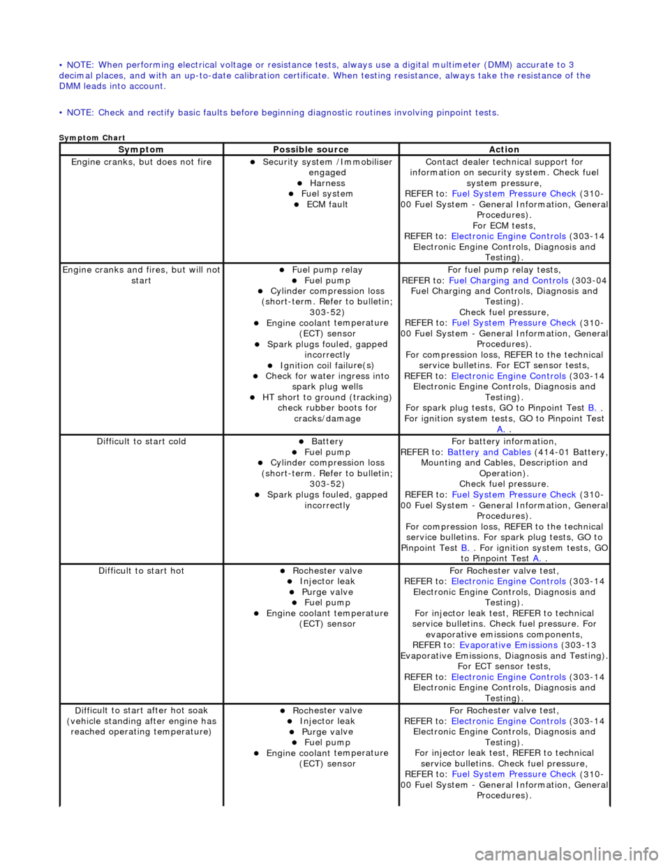
• NO
TE: When performing electrical voltag
e or resistance tests, always use a digital multimeter (DMM) accurate to 3
decimal places, and with an up-t o-date calibration certificate. When testing resistance, always take the resistance of the
DMM leads into account.
• NOTE: Check and rectify basic faults before beginning diagnostic ro utines involving pinpoint tests.
Sym
ptom Chart
Sy
m
ptom
Possib
l
e source
Acti
o
n
Engine
cranks, but does
not fire
Secu
rit
y system /Immobiliser
engaged
Harness Fue l
system
ECM fault
Contact deal er techni
cal support for
information on security system. Check fuel
system pressure,
REFER to: Fuel System Pressure Check
(310
-
00 Fuel System - Genera l Information, General
Procedures).
For ECM tests,
REFER to: Electronic Engine Controls
(303
-14
Electronic Engine Co ntrols, Diagnosis and
Testing).
Engine cranks and
fi
res, but will not
start
Fu
el pump relay
Fuel
pump
Cyl
i
nder compression loss
(short-term. Refer to bulletin; 303-52)
Engine coolan t
temperature
(ECT) sensor
Spark plugs fouled, gapp
ed
incorrectly
Ignition coil fail
ure(s)
Check f
o
r water ingress into
spark plug wells
HT sho rt to ground (tracking)
check rubber
boots for
cracks/damage
Fo
r fuel pump relay tests,
REFER to: Fuel Charging and Controls
(303
-04
Fuel Charging and Controls, Diagnosis and Testing).
Check fuel pressure,
REFER to: Fuel System Pressure Check
(310
-
00 Fuel System - Genera l Information, General
Procedures).
For compression loss, REFER to the technical service bulletins. For ECT sensor tests,
REFER to: Electronic Engine Controls
(303
-14
Electronic Engine Co ntrols, Diagnosis and
Testing).
For spark plug tests, GO to Pinpoint Test B.
.
For ign i
tion system tests, GO to Pinpoint Test
A.
.
Diff
icult to start cold
Batt
ery Fuel
pump
Cyl
i
nder compression loss
(short-term. Refer to bulletin; 303-52)
Spark plugs fouled, gapp
ed
incorrectly
F o
r battery information,
REFER to: Battery and Cables
(414
-01 Battery,
Mounting and Cables, Description and Operation).
Check fuel pressure.
REFER to: Fuel System Pressure Check
(310
-
00 Fuel System - Genera l Information, General
Procedures).
For compression loss, REFER to the technical service bulletins. For spark plug tests, GO to
Pinpoint Test B.
. For ig
nition system tests, GO
to Pinpoint Test A.
.
Diff
icult to start hot
Roc
h
ester valve
Injec
t
or leak
Purge
val
ve
Fue
l
pump
Engine coolan
t
temperature
(ECT) sensor
F or R
ochester
valve test,
REFER to: Electronic Engine Controls
(303
-14
Electronic Engine Co ntrols, Diagnosis and
Testing).
For injector leak test, REFER to technical
service bulletins. Check fuel pressure. For evaporative emissions components,
REFER to: Evaporative Emissions
(303
-13
Evaporative Emissions, Diagnosis and Testing).
For ECT sensor tests,
REFER to: Electronic Engine Controls
(303
-14
Electronic Engine Co ntrols, Diagnosis and
Testing).
D iff
icult to start after hot soak
(vehicle standing after engine has reached operating temperature)
Roc h
ester valve
Injec
t
or leak
Purge
val
ve
Fue
l
pump
Engine coolan
t
temperature
(ECT) sensor
F or R
ochester
valve test,
REFER to: Electronic Engine Controls
(303
-14
Electronic Engine Co ntrols, Diagnosis and
Testing).
For injector leak test, REFER to technical service bulletins. Check fuel pressure,
REFER to: Fuel System Pressure Check
(310
-
00 Fuel System - Genera l Information, General
Procedures).
Page 1079 of 2490
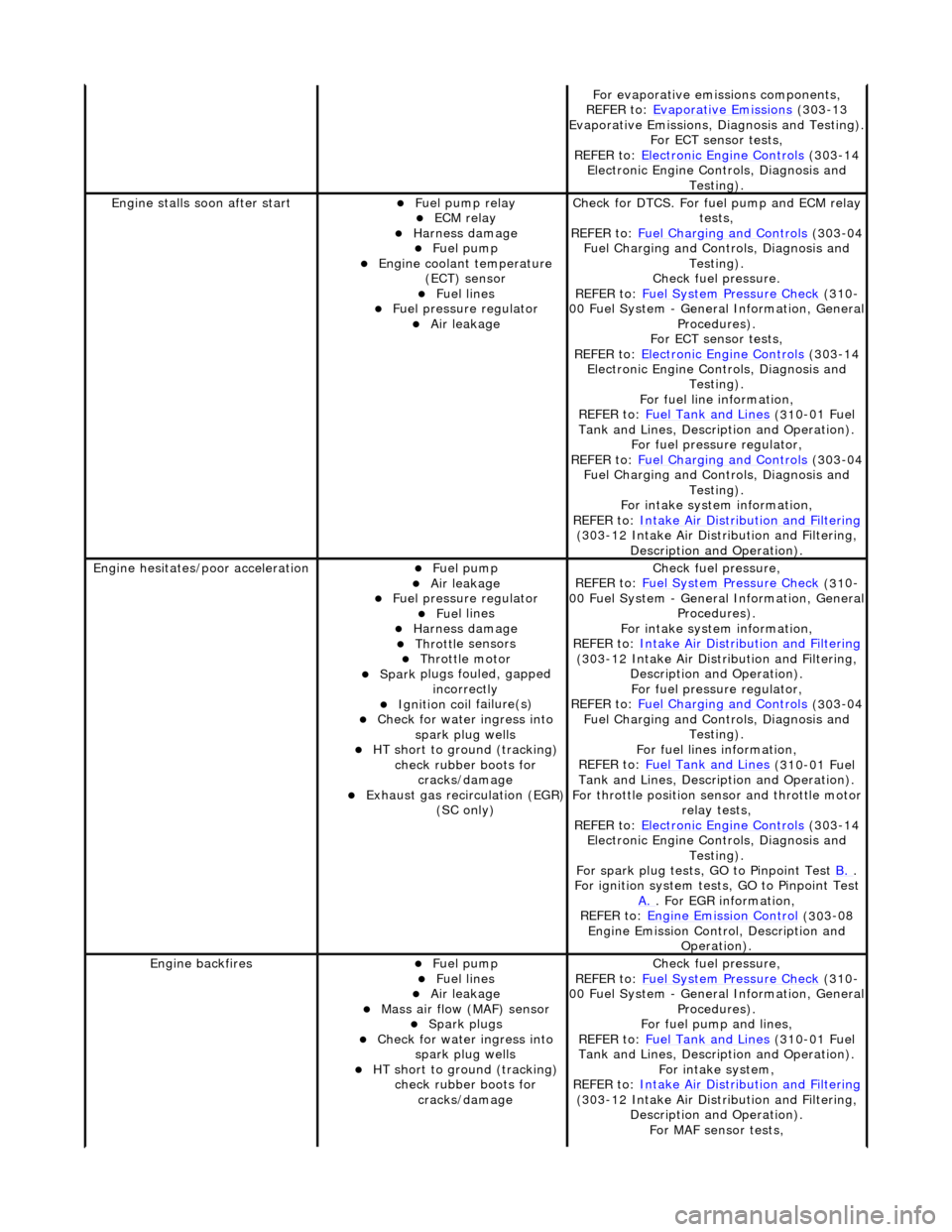
F
or evaporative emissions components,
REFER to: Evaporative Emissions
(30
3-13
Evaporative Emissions, Diagnosis and Testing).
For ECT sensor tests,
REFER to: Electronic Engine Controls
(30
3-14
Electronic Engine Co ntrols, Diagnosis and
Testing).
Engine stalls
soon after start
F
uel pump relay
ECM relay
Harness damage Fue
l pump
Engine coolan
t temperature
(ECT) sensor
Fue
l lines
F
uel pressure regulator
Air leakage
Check f
or DTCS. For fuel pump and ECM relay
tests,
REFER to: Fuel Charging and Controls
(30
3-04
Fuel Charging and Controls, Diagnosis and Testing).
Check fuel pressure.
REFER to: Fuel System Pressure Check
(31
0-
00 Fuel System - Genera l Information, General
Procedures).
For ECT sensor tests,
REFER to: Electronic Engine Controls
(30
3-14
Electronic Engine Co ntrols, Diagnosis and
Testing).
For fuel line information,
REFER to: Fuel Tank and Lines
(31
0-01 Fuel
Tank and Lines, Description and Operation).
For fuel pressure regulator,
REFER to: Fuel Charging and Controls
(30
3-04
Fuel Charging and Controls, Diagnosis and Testing).
For intake system information,
REFER to: Intake Air Distribution and Filtering
(30
3-12 Intake Air Distribution and Filtering,
Description and Operation).
Engine hesi
tates/poor acceleration
Fue
l pump
Air leakage
F
uel pressure regulator
Fue
l lines
Harness damage Throttl
e sensors
Throttl
e motor
Spark
plugs fouled, gapped
incorrectly
Ignition coil
failure(s)
Check f
or water ingress into
spark plug wells
HT sho
rt to ground (tracking)
check rubber boots for cracks/damage
Exhaus
t gas recirculation (EGR)
(SC only)
Chec
k fuel pressure,
REFER to: Fuel System Pressure Check
(31
0-
00 Fuel System - Genera l Information, General
Procedures).
For intake system information,
REFER to: Intake Air Distribution and Filtering
(30
3-12 Intake Air Distribution and Filtering,
Description and Operation). For fuel pressure regulator,
REFER to: Fuel Charging and Controls
(30
3-04
Fuel Charging and Controls, Diagnosis and Testing).
For fuel lines information,
REFER to: Fuel Tank and Lines
(31
0-01 Fuel
Tank and Lines, Description and Operation).
For throttle position se nsor and throttle motor
relay tests,
REFER to: Electronic Engine Controls
(30
3-14
Electronic Engine Co ntrols, Diagnosis and
Testing).
For spark plug tests, GO to Pinpoint Test B.
.
For ign
ition system tests, GO to Pinpoint Test
A.
. F
or EGR information,
REFER to: Engine Emission Control
(30
3-08
Engine Emission Cont rol, Description and
Operation).
Engine ba
ckfires
Fue
l pump
Fue
l lines
Air leakage
Mass ai
r flow (MAF) sensor
Spark plugs
Check f
or water ingress into
spark plug wells
HT sho
rt to ground (tracking)
check rubber boots for cracks/damage
Chec
k fuel pressure,
REFER to: Fuel System Pressure Check
(31
0-
00 Fuel System - Genera l Information, General
Procedures).
For fuel pump and lines,
REFER to: Fuel Tank and Lines
(31
0-01 Fuel
Tank and Lines, Description and Operation).
For intake system,
REFER to: Intake Air Distribution and Filtering
(30
3-12 Intake Air Distribution and Filtering,
Description and Operation). For MAF sensor tests,
Page 1080 of 2490
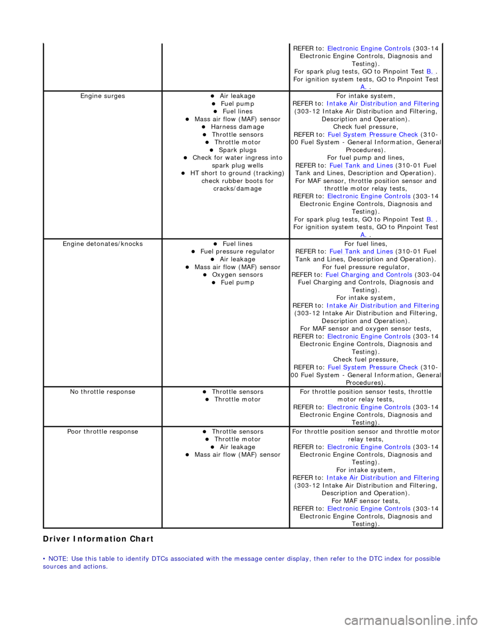
Driver Information
Chart
•
NOTE: Use this table to identify DTCs associated with the me
ssage center display, then refer to the DTC index for possible
sources and actions.
REF E
R to:
Electronic Engine Controls
(303
-14
Electronic Engine Co ntrols, Diagnosis and
Testing).
For spark plug tests, GO to Pinpoint Test B.
.
For ign i
tion system tests, GO to Pinpoint Test
A.
.
Engine s
urges
Air leakage
Fue
l
pump
Fue
l
lines
Mass ai
r fl
ow (MAF) sensor
Harness damage Throttl
e
sensors
Throttl
e
motor
Spark plugs
Check fo
r water ingress into
spark plug wells
HT short to ground (tracking) check rubber
boots for
cracks/damage
Fo r
intake system,
REFER to: Intake Air Distribution and Filtering
(30 3
-12 Intake Air Distribution and Filtering,
Description and Operation). Check fuel pressure,
REFER to: Fuel System Pressure Check
(310
-
00 Fuel System - Genera l Information, General
Procedures).
For fuel pump and lines,
REFER to: Fuel Tank and Lines
(310
-01 Fuel
Tank and Lines, Description and Operation).
For MAF sensor, throttle position sensor and
throttle motor relay tests,
REFER to: Electronic Engine Controls
(303
-14
Electronic Engine Co ntrols, Diagnosis and
Testing).
For spark plug tests, GO to Pinpoint Test B.
.
For ign i
tion system tests, GO to Pinpoint Test
A.
.
Engine detonates/k
nocks
Fue
l
lines
F
u
el pressure regulator
Air leakage
Mass air fl
ow (MAF) sensor
O
xygen senso
rs
Fue
l
pump
F
o
r fuel lines,
REFER to: Fuel Tank and Lines
(310
-01 Fuel
Tank and Lines, Description and Operation).
For fuel pressure regulator,
REFER to: Fuel Charging and Controls
(303
-04
Fuel Charging and Controls, Diagnosis and Testing).
For intake system,
REFER to: Intake Air Distribution and Filtering
(30 3
-12 Intake Air Distribution and Filtering,
Description and Operation).
For MAF sensor and oxyg en sensor tests,
REFER to: Electronic Engine Controls
(303
-14
Electronic Engine Co ntrols, Diagnosis and
Testing).
Check fuel pressure,
REFER to: Fuel System Pressure Check
(310
-
00 Fuel System - Genera l Information, General
Procedures).
No t
hrottle response
Throttl
e
sensors
Throttl
e
motor
Fo
r th
rottle position sensor tests, throttle
motor relay tests,
REFER to: Electronic Engine Controls
(303
-14
Electronic Engine Co ntrols, Diagnosis and
Testing).
Poor throttle responseThrottl e
sensors
Throttl
e
motor
Air leakage Mass air fl
ow (MAF) sensor
F
or throttl
e position se
nsor and throttle motor
relay tests,
REFER to: Electronic Engine Controls
(303
-14
Electronic Engine Co ntrols, Diagnosis and
Testing).
For intake system,
REFER to: Intake Air Distribution and Filtering
(30 3
-12 Intake Air Distribution and Filtering,
Description and Operation). For MAF sensor tests,
REFER to: Electronic Engine Controls
(303
-14
Electronic Engine Co ntrols, Diagnosis and
Testing).
Page 1094 of 2490
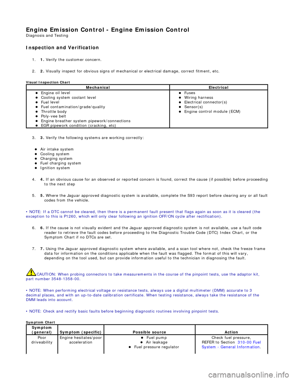
Engine Emission
Control - Engine Emission Control
D
iagn
osis and Testing
I
n
spection and Verification
1.
1. Veri fy the customer concern.
2. 2. Vis
ually inspect for obvious signs of mechanical
or electrical damage, correct fitment, etc.
Vi
sual Inspection Chart
3.
3. Veri fy the foll
owing syst
ems are working correctly:
Air intake
system
Coo
ling system
Charging system
Fu
el charging system
Ignition sys
t
em
4. 4. If an obvious cause for an observed or reported concern is found, correct the cause (if possible) before proceeding
to the next step
5. 5. Where the Jaguar approved diagnostic sy stem is available, complete the S93 report before clearing any or all fault
codes from the vehicle.
• NOTE: If a DTC cannot be cleared, then there is a permanent fault present that flag s again as soon as it is cleared (the
exception to this is P1260, which will only clear following an ignition OFF/ON cycle after rectification).
6. 6. If the cause is not visually evident and the Jaguar approv ed diagnostic system is not available, use a fault code
reader to retrieve the fault codes be fore proceeding to the Diagnostic Trou ble Code (DTC) Index Chart, or the
Symptom Chart if no DTCs are set.
7. 7. Using the Jaguar approved diagnostic system where available, and a scan tool where not, check the freeze frame
data for information on the conditions applicable when the fault was flagged. The format of this will vary,
depending on the tool used, but can pr ovide information useful to the technician in diagnosing the fault.
CAUTION: When probing connectors to take measurements in the course of the pinpoint tests, use the adaptor kit,
part number 3548-1358-00.
• NOTE: When performing electrical voltag e or resistance tests, always use a digital multimeter (DMM) accurate to 3
decimal places, and with an up-t o-date calibration certificate. When testing resistance, always take the resistance of the
DMM leads into account.
• NOTE: Check and rectify basic faults before beginning diagnostic ro utines involving pinpoint tests.
Sym
ptom Chart
MechanicalElectrical
Engi
ne
oil level
Coo
ling system coolant level
Fue
l
level
Fuel contaminatio
n
/
grade/quality
Throttle body Poly
-ve
e belt
Engine breath
er
system
pipework/connections
EGR pipework
condition (cracking, etc)
F
u
ses
W
i
ring harness
E
l
ectrical connector(s)
Sens
o
r(s)
Engine
control module (E
CM)
Sy
m
ptom
(general)
S y
mptom (specific)
Possib
l
e source
Acti
o
n
Poor
dr iveabilityEngine h e
sitates/poor
acceleration
Fue l
pump
Air leakage F
u
el pressure regulator
Chec
k fu
el pressure,
REFER to Section 310
-00 Fu
el
Sy
ste
m
- General Informati
on.
Page 1151 of 2490
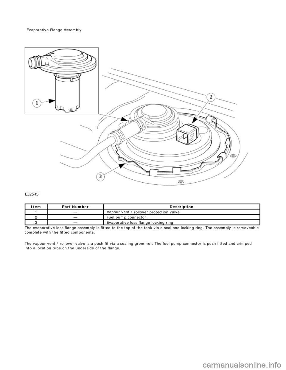
The evaporative l
oss flange assembly is fitted to the top of the tank via a seal and locking ring. The assembly is removeable
complete with the fitted components.
The vapour vent / rollover valve is a push fit via a sealing grommet. The fuel pump connector is push fitted and crimped
into a location tube on the underside of the flange.
It
em
Par
t Number
De
scription
1—Vapour vent /
rollover protection valve
2—Fue
l pump connector
3—Evaporative loss flange locking rin
g
Evaporative Flang
e Assembly
Page 1153 of 2490
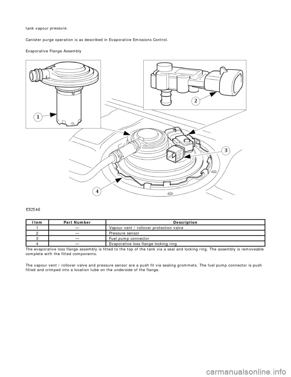
tank vapou
r pressure.
Canister purge operation is as described in Evaporative Emissions Control.
Evaporative Flange Assembly
The evaporative loss flange assembly is fitted to the top of the tank via a seal and locking ring. The assembly is removeable
complete with the fitted components.
The vapour vent / rollover valve and pressure sensor are a pu sh fit via sealing grommets. The fuel pump connector is push
fitted and crimped into a location tu be on the underside of the flange.
It
em
Par
t Number
De
scription
1—Vapour vent /
rollover protection valve
2—Pres
sure sensor
3—Fue
l pump connector
4—Evaporative loss flange locking rin
g