1998 JAGUAR X308 fuel pump
[x] Cancel search: fuel pumpPage 1158 of 2490
The fuel fil
ler cap is the same as
that used on non-ORVR systems.
The check valve assembly is a push fit into the end of the fuel filler tube and is accessible with the evaporative flange
removed. The valve has a light spring load ing and opens under the inflow of fuel.
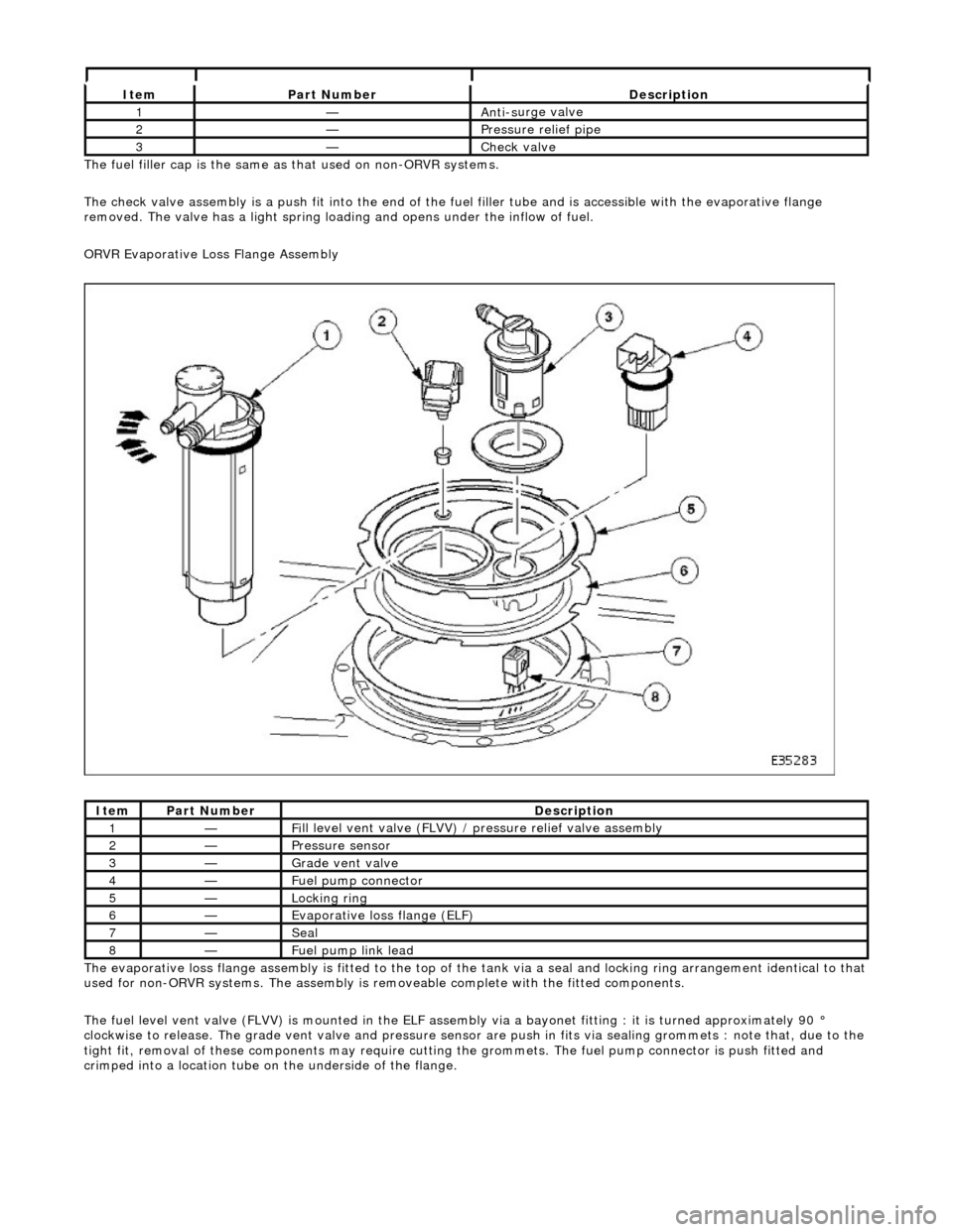
ORVR Evaporative Loss Flange Assembly
The evaporative loss flange assembly is fitted to the top of the tank via a seal and locking ring arrangement identical to that
used for non-ORVR systems. The assembly is re moveable complete with the fitted components.
The fuel level vent valve (FLVV) is mounted in the ELF assembly via a bayonet fitting : it is turned approximately 90 °
clockwise to release. The grade vent valve and pressure sensor are push in fits via sealing gromme ts : note that, due to the
tight fit, removal of these components may require cutting the grommets. The fuel pump connector is push fitted and
crimped into a location tube on the underside of the flange.
It e
m
Par
t
Number
De
scr
iption
1—An
ti-s
urge valve
2—Pressure rel
i
ef pipe
3—Check v
a
lve
It
e
m
Par
t
Number
De
scr
iption
1—Fi
ll
level vent valve (FLVV) /
pressure relief valve assembly
2—Pres
sure
sensor
3—Grade vent
valve
4—Fue
l
pump connector
5—Lockin
g rin
g
6—Evaporative loss flange (ELF)
7—Seal
8—F
u
el pump link lead
Page 1171 of 2490
E
vaporative Emissions - Fuel
Tank Pressure Sensor
Re
moval and Installation
Remov
al
Installation
1.
Disc
onnect battery ground cable (IMPORTANT, see SRO
86.15.19 for further information).
2. WARNING: BEFORE PROCEEDING, IT IS ESSENTIAL THAT
THE WARNING NOTES GIVEN IN SECTION 100-00 (UNDER THE
HEADING 'SAFETY PRECAUTIONS') ARE READ AND
UNDERSTOOD.
Drain the fuel tank using a suitab le suction pump/tanker. If the
On-board Refueling Vapor Recove ry (ORVR) system is fitted,
refer to General Procedures Section 310-01.
3. R
emove the fuel tank; refe
r to operation 19.55.01.
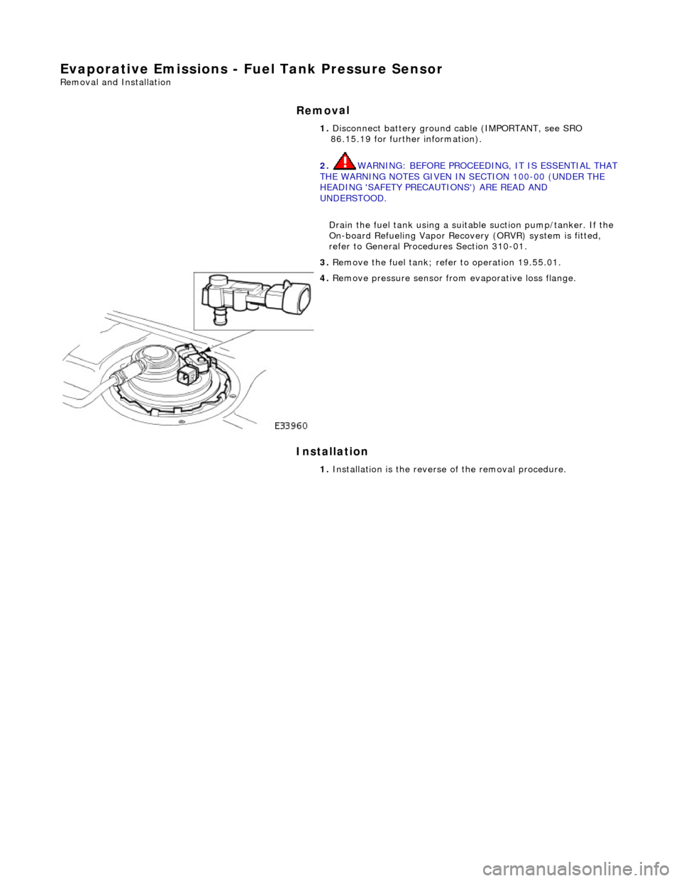
4. R
emove pressure sensor fro
m evaporative loss flange.
1. Installation is th e reverse of the re moval procedure.
Page 1173 of 2490
Evapor
ative Emissions - Fuel Va
por Vent Valve Housing Seal
Remov
al and Installation
Re
moval
• NO
TE: The Removal and Installation procedur
es below show one type of flange but are applicable to the other evaporative loss systems
described.
Special To
ol(s)
Lock
Ring Wrench - Fuel Tank Flange
412-070 (JD 174)
1. Remove battery. Refer to 86.15.01.
2. WARNING: BEFORE PROCEEDING, IT IS ESSENTIAL THAT THE
WARNING NOTES GIVEN IN SECTIO N 100-00 (UNDER THE HEADING
'SAFETY PRECAUTIONS') ARE READ AND UNDERSTOOD.
Remove fuel tank assembly for access. Refer to operation 19.55.01.
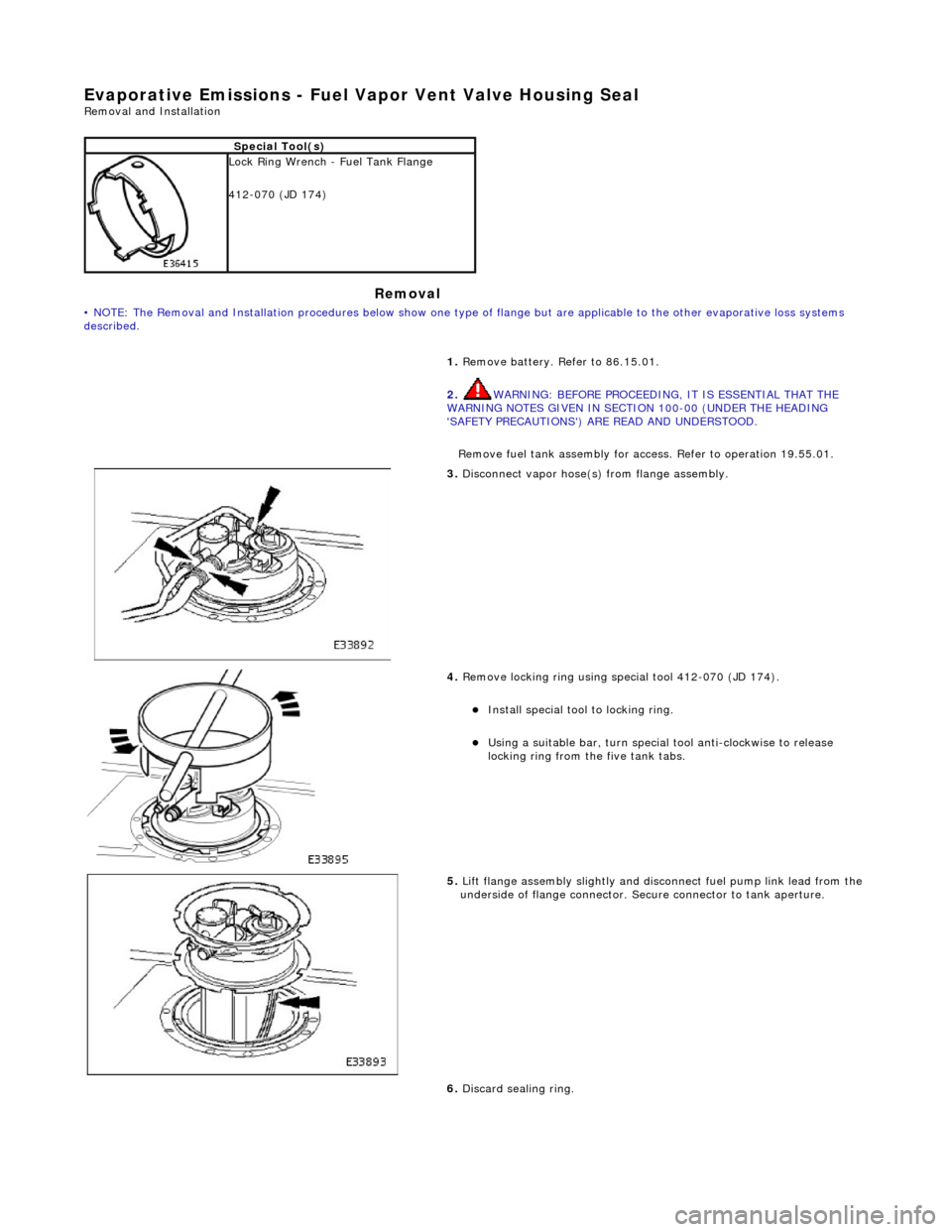
3. Discon
nect vapor hose(s) from flange assembly.
4. Remov
e locking ring using special tool 412-070 (JD 174).
Insta
ll special tool to locking ring.
Usi
ng a suitable bar, turn special tool anti-clockwise to release
locking ring from the five tank tabs.
5. Lift
flange assembly slightly and disconnect fuel pump link lead from the
underside of flange connector. Secure connector to tank aperture.
6. Discard sealing ring.
Page 1174 of 2490
Installation
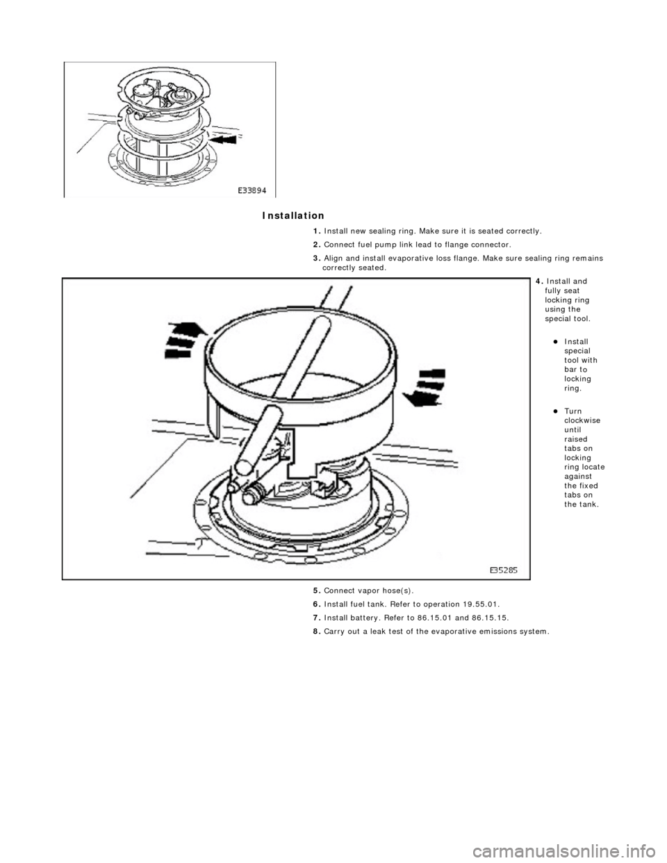
1.
Insta ll n
ew sealing ring. Make sure it is seated correctly.
2. Connect fuel pump link lead to flange connector.
3. Align and install evaporative loss flange. Make sure sealing ring remains
correctly seated.
4. Insta ll a
nd
fully seat
locking ring
using the
special tool.
Insta ll
special
tool with
bar t
o
locking
ring.
Turn
clock w
ise
until
raised
tabs on
locking
ring locate
against
the fixed
tabs on
the tank.
5. Connect vapor hose(s).
6. Install fuel tank. Refer to operation 19.55.01.
7. Install battery. Refer to 86.15.01 and 86.15.15.
8. Carry out a leak test of the evaporative emissions system.
Page 1190 of 2490
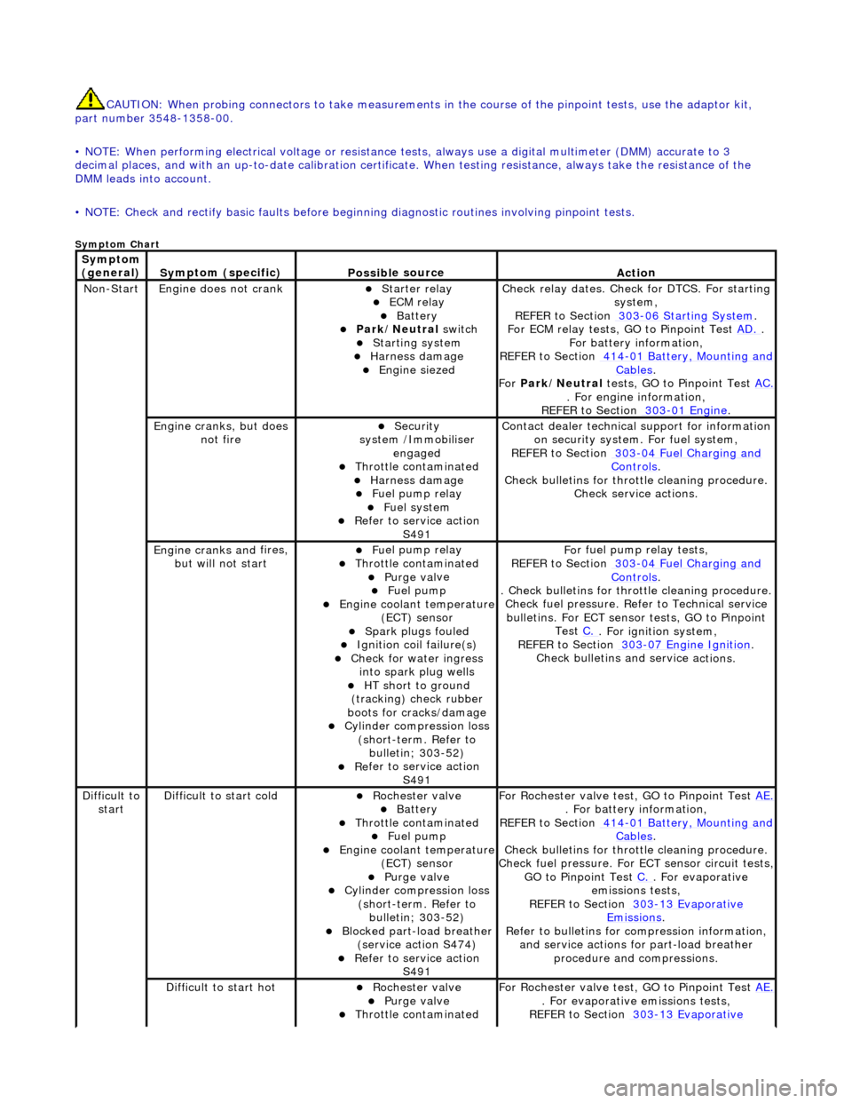
CAUTIO
N: When probing connectors to take
measurements in the course of the pinpoint tests, use the adaptor kit,
part number 3548-1358-00.
• NOTE: When performing electrical voltag e or resistance tests, always use a digital multimeter (DMM) accurate to 3
decimal places, and with an up-t o-date calibration certificate. When testing resistance, always take the resistance of the
DMM leads into account.
• NOTE: Check and rectify basic faults before beginning diagnostic ro utines involving pinpoint tests.
Sym
ptom Chart
Sym
ptom
(general)
S y
mptom (specific)
Possib
l
e source
Acti
o
n
No
n
-Start
Engine
does not cran
k
Starter relay ECM relay Batt
ery Park
/Neutral
switch
Starting system
Harness damage
Engine s
iezed
Check r
e
lay dates. Check
for DTCS. For starting
system,
REFER to Section 303
-06 Sta r
ting System
.
F or ECM
relay tests, GO to Pinpoint Test
AD.
.
F o
r battery information,
REFER to Section 414
-0 1
Battery, Mounting and
Cables.
Fo r
Park/Neutral tests, GO to Pinpoint Test AC.
. Fo
r engine information,
REFER to Section 303
-01 En
gine
.
Engine cranks, but does
not fireSecurity
syst
em /Immobiliser
engaged
Thr o
ttle contaminated
Harness damage
Fu
el pump relay
Fue
l
system
R
e
fer to service action
S491
Contact dealer techni
cal
support for information
on security system. For fuel system,
REFER to Section 303
-0 4
Fuel Charging and
Controls.
Check bull etins for throttl
e cleaning procedure.
Check service actions.
Engine cranks an d
fires,
but will not start
F u
el pump relay
Thr
o
ttle contaminated
Purge
val
ve
Fue
l
pump
Engine coolan
t
temperature
(ECT) sensor
Spark plugs
fouled
Ignition coil
fail
ure(s)
Check f
o
r water ingress
into spark plug wells
HT sh o
rt to ground
(tracking) check rubber
boots for cracks/damage
Cyli
nder compression loss
(short-term. Refer to bulletin; 303-52)
Re
fer to service action
S491
Fo
r fuel pump relay tests,
REFER to Section 303
-0 4
Fuel Charging and
Controls.
. Check bulletins for throttl
e cleaning procedure.
Check fuel pressure. Refe r to Technical service
bulletins. For ECT sensor tests, GO to Pinpoint Test C.
. Fo
r ignition system,
REFER to Section 303
-07 En
gine Ignition
.
Check bulletins an d service a
ctions.
Di
f
ficult to
start
D iff
icult to start cold
Roc
h
ester valve
Batt
ery Thro
ttle contaminated
Fue
l
pump
Engine coolan
t
temperature
(ECT) sensor
Purge val
ve
Cyl
i
nder compression loss
(short-term. Refer to bulletin; 303-52)
Blocked part-load breather (s
ervice action S474)
R
e
fer to service action
S491
For R
ochester valv
e test, GO to Pinpoint Test AE.
. Fo
r battery information,
REFER to Section 414
-0 1
Battery, Mounting and
Cables.
Check bull etins for throttl
e cleaning procedure.
Check fuel pressure. For ECT sensor circuit tests,
GO to Pinpoint Test C.
. F
or evaporative
emissions tests,
REFER to Section 303
-1 3
Evaporative
Emiss
i
ons
.
R e
fer to bulletins for co
mpression information,
and service actions for part-load breather procedure and compressions.
Diff
icult to start hot
Roc
h
ester valve
Purge
val
ve
Thr
o
ttle contaminated
F
or R
ochester valv
e test, GO to Pinpoint Test AE.
. F
or evaporative emissions tests,
REFER to Section 303
-1 3
Evaporative
Page 1191 of 2490
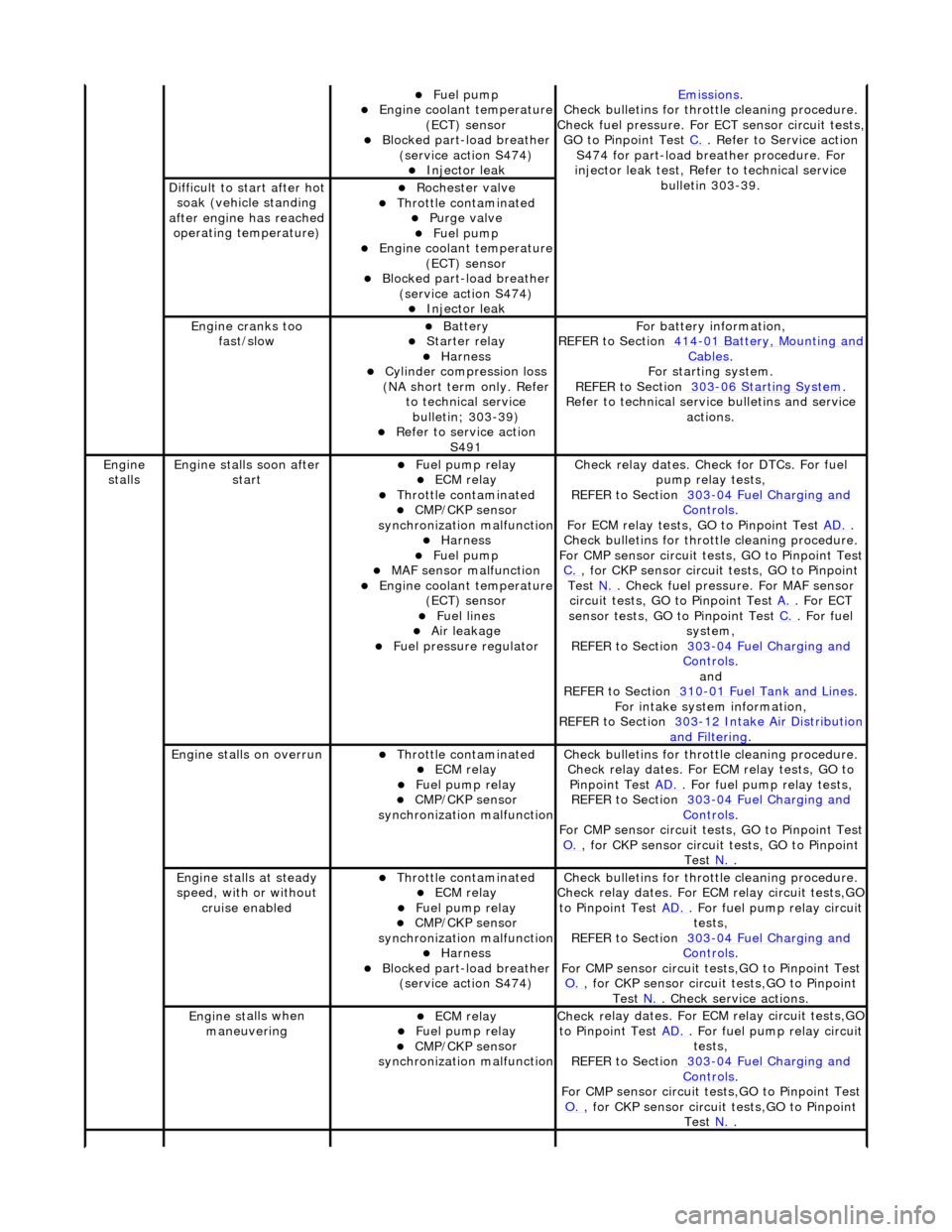
Fue
l pump
Engine coolan
t temperature
(ECT) sensor
Blocked part-load breather (
service action S474)
Injec
tor leak
Emiss
ions
.
Check bull
etins for throttle cleaning procedure.
Check fuel pressure. For ECT sensor circuit tests,
GO to Pinpoint Test C.
. Refer to Servi
ce action
S474 for part-load breather procedure. For
injector leak test, Refer to technical service bulletin 303-39.
D
ifficult to start after hot
soak (vehicle standing
after engine has reached operating temperature)
Roc
hester valve
Thr
ottle contaminated
Purge
valve
Fue
l pump
Engine coolan
t temperature
(ECT) sensor
Blocked part-load breather (
service action S474)
Injec
tor leak
Engine cranks too
fa
st/slow
Batt
ery
Starter relay Harness Cyl
inder compression loss
(NA short term only. Refer to technical service bulletin; 303-39)
R
efer to service action
S491
F
or battery information,
REFER to Section 414
-0
1 Battery, Mounting and
Cables.
F
or starting system.
REFER to Section 303
-06 Sta
rting System
.
R
efer to technical servic
e bulletins and service
actions.
Engine
stalls
Engine st
alls soon after
start
F
uel pump relay
ECM relay Thr
ottle contaminated
CMP/CKP sen
sor
synchronization malfunction
Harness Fue
l pump
MAF
sensor malfunction
Engine coolan
t temperature
(ECT) sensor
Fue
l lines
Air leakage
F
uel pressure regulator
Check r
elay dates. Chec
k for DTCs. For fuel
pump relay tests,
REFER to Section 303
-0
4 Fuel Charging and
Controls.
F
or ECM relay tests, GO to Pinpoint Test
AD.
.
Check bull
etins for throttle cleaning procedure.
For CMP sensor circuit test s, GO to Pinpoint Test
C.
, for
CKP sensor circuit tests, GO to Pinpoint
Test N.
. Check fuel
pressure. For MAF sensor
circuit tests, GO to Pinpoint Test A.
. For EC
T
sensor tests, GO to Pinpoint Test C.
. F
or fuel
system,
REFER to Section 303
-0
4 Fuel Charging and
Controls.
and
REF
ER to Section 310
-0
1 Fuel Tank and Lines
. F
or intake system information,
REFER to Section 303
-1
2 Intake Air Distribution
and F
iltering
.
Engine
stalls on overrun
Thr
ottle contaminated
ECM relay F
uel pump relay
CMP/CKP sen
sor
synchronization malfunction
Check bull
etins for throttle cleaning procedure.
Check relay dates. For ECM relay tests, GO to Pinpoint Test AD.
. F
or fuel pump relay tests,
REFER to Section 303
-0
4 Fuel Charging and
Controls.
F
or CMP sensor circuit test
s, GO to Pinpoint Test
O.
, for
CKP sensor circuit tests, GO to Pinpoint
Test N.
.
E
ngine stalls at steady
speed, with or without cruise enabled
Thr
ottle contaminated
ECM relay F
uel pump relay
CMP/CKP sen
sor
synchronization malfunction
Harness Blocked part-load breather
(
service action S474)
Check bull
etins for throttle cleaning procedure.
Check relay dates. For EC M relay circuit tests,GO
to Pinpoint Test AD.
. F
or fuel pump relay circuit
tests,
REFER to Section 303
-0
4 Fuel Charging and
Controls.
F
or CMP sensor circuit test
s,GO to Pinpoint Test
O.
, for
CKP sensor circuit tests,GO to Pinpoint
Test N.
. Che
ck service actions.
Engine st
alls when
maneuvering
ECM relay F
uel pump relay
CMP/CKP sen
sor
synchronization malfunction
Check r
elay dates. For EC
M relay circuit tests,GO
to Pinpoint Test AD.
. F
or fuel pump relay circuit
tests,
REFER to Section 303
-0
4 Fuel Charging and
Controls.
F
or CMP sensor circuit test
s,GO to Pinpoint Test
O.
, for
CKP sensor circuit tests,GO to Pinpoint
Test N.
.
Page 1192 of 2490
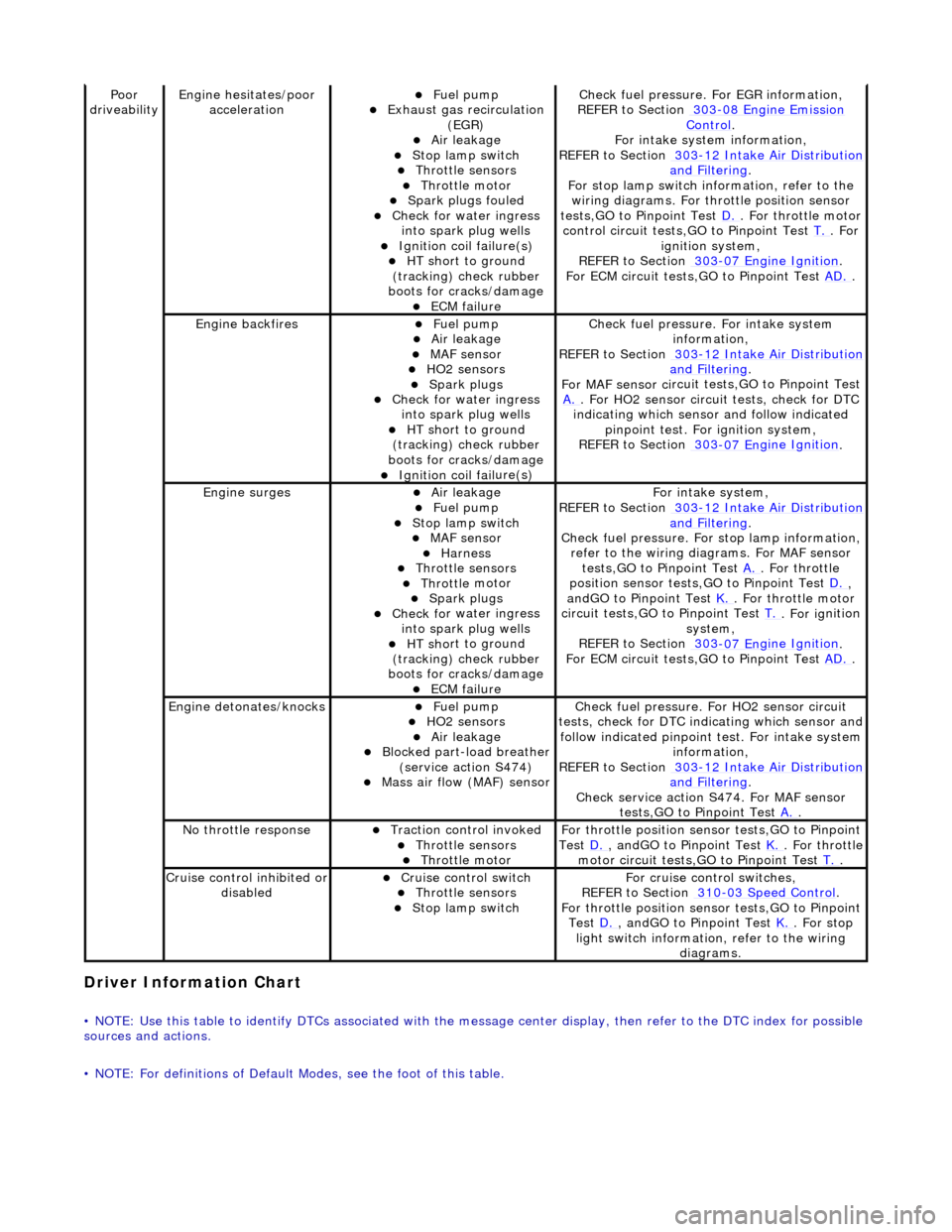
Driver Information
Chart
•
NOTE: Use this table to identify DTCs associated with the me
ssage center display, then refer to the DTC index for possible
sources and actions.
• NOTE: For definitions of Default Modes, see the foot of this table.
Poor
dr iveabilityEngine h e
sitates/poor
acceleration
Fue l
pump
Exhaus
t gas
recirculation
(EGR)
Air leakage Stop lamp swi t
ch
Throttl
e
sensors
Throttl
e
motor
Spark
plugs
fouled
Check f
o
r water ingress
into spark plug wells
Ignition coil fail
ure(s)
HT sh
o
rt to ground
(tracking) check rubber
boots for cracks/damage
ECM failu r
e
Check f
u
el pressure. For EGR information,
REFER to Section 303
-08 En gin
e Emission
Control.
F or i
ntake system information,
REFER to Section 303
-1 2
Intake Air Distribution
and F
ilt
ering
.
F or stop l
amp switch in
formation, refer to the
wiring diagrams. For throttle position sensor
tests,GO to Pinpoint Test D.
. Fo
r throttle motor
control circuit tests,GO to Pinpoint Test T.
. For
igni t
ion system,
REFER to Section 303
-07 En
gine Ignition
.
F or ECM
circuit tests,GO to Pinpoint Test
AD.
.
Engine backfiresFuel
pump
Air leakage MAF se
nsor
HO2 sensors
Spark plugs Check fo
r water ingress
into spark plug wells
HT sh o
rt to ground
(tracking) check rubber
boots for cracks/damage
Ignition coil fail
ure(s)
Chec
k fu
el pressure. For intake system
information,
REFER to Section 303
-12
Intake Air Distribution
and Filt
ering
.
F or MAF sensor ci
rcuit test
s,GO to Pinpoint Test
A.
. F or HO2 sensor
circui
t tests, check for DTC
indicating which sensor and follow indicated pinpoint test. For ignition system,
REFER to Section 303
-07 En
gine Ignition
.
Engine
s
urges
Air leakage
Fuel
pump
Stop lamp swit
ch
MAF s
e
nsor
Harness Throttl
e
sensors
Throttl
e
motor
Spark plugs
Check fo
r water ingress
into spark plug wells
HT sh o
rt to ground
(tracking) check rubber
boots for cracks/damage
ECM failu r
e
Fo
r
intake system,
REFER to Section 303
-1 2
Intake Air Distribution
and Filt
ering
.
Check fu
el pressure. For
stop lamp information,
refer to the wiring diagrams. For MAF sensor tests,GO to Pinpoint Test A.
. Fo
r throttle
position sensor tests,GO to Pinpoint Test D.
,
a n
dGO to Pinpoint Test
K.
. Fo
r throttle motor
circuit tests,GO to Pinpoint Test T.
. For ig
nition
system,
REFER to Section 303
-07 En
gine Ignition
.
F or ECM
circuit tests,GO to Pinpoint Test
AD.
.
Engine detonates/k
nocks
Fue
l
pump
HO2 sensors
Air leakage Blocked part-load breather
(s
ervice action S474)
Mass ai
r fl
ow (MAF) sensor
Chec
k fu
el pressure. Fo
r HO2 sensor circuit
tests, check for DTC indicating which sensor and
follow indicated pinpoint test. For intake system
information,
REFER to Section 303
-1 2
Intake Air Distribution
and Filt
ering
.
Check service action S474
. For MAF sensor
tests,GO to Pinpoint Test A.
.
No t
hrottle response
Traction contr
o
l invoked
Throttl
e
sensors
Throttl
e
motor
Fo
r th
rottle position sensor tests,GO to Pinpoint
Test D.
, andG O to Pinpoint
Test
K.
. Fo
r throttle
motor circuit tests,GO to Pinpoint Test T.
.
Cru i
se control inhibited or
disabled
Cru i
se control switch
Throttle
sensors
Stop lamp swit
ch
For cru
i
se control switches,
REFER to Section 310
-03
Speed Control
.
For th
rottle position sensor tests,GO to Pinpoint
Test D.
, andG O to Pinpoint
Test
K.
. For s t
op
light switch information, refer to the wiring diagrams.
Page 1197 of 2490
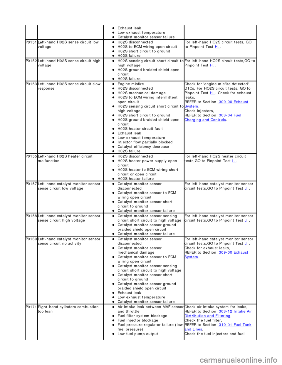
Exhaus
t leak
Low e
xhaust temperature
Cat
alyst monitor sensor failure
P0151Le
ft-hand H02S sense circuit low
voltage
H02
S disconnected
H0
2S to ECM wiring open circuit
H0
2S short circuit to ground
H0
2S failure
F
or left-hand HO2S circuit tests, GO
to Pinpoint Test H.
.
P0152Le
ft-hand H02S sense circuit high
voltage
H02
S sensing circuit short circuit to
high voltage
H0
2S ground braided shield open
circuit
H0
2S failure
F
or left-hand HO2S circuit tests,GO to
Pinpoint Test H.
.
P0153Le
ft-hand H02S sense circuit slow
response
Engine
misfire
H02
S disconnected
H0
2S mechanical damage
H0
2S to ECM wiring intermittent
open circuit
H02
S sensing circuit short circuit to
high voltage
H0
2S short circuit to ground
H0
2S ground braided shield open
circuit
H0
2S heater circuit fault
Exhaus
t leak
Low e
xhaust temperature
Injector fl
ow partially blocked
Catal
yst efficiency decrease
H0
2S failure
Chec
k for 'engine misfire detected'
DTCs. For HO2S circ uit tests, GO to
Pinpoint Test H.
. Check for exhaust
leak
s,
REFER to Section 309
-00
Exhaust
Sy
stem
.
Chec
k injectors,
REFER to Section 303
-04
Fuel
Charging and Con
trols
.
P0155Left-hand H02S heater
circuit
malfunction
H02
S disconnected
H0
2S heater power supply open
circuit
H0
2S heater to ECM wiring short
circuit or open circuit
H0
2S heater failure
F
or left-hand HO2S heater circuit
tests,GO to Pinpoint Test I.
.
P0157Le
ft-hand catalyst monitor sensor
sense circuit low voltage
Catal
yst monitor sensor
disconnected
Catal
yst monitor sensor to ECM
wiring open circuit
Catal
yst monitor sensor short
circuit to ground
Cat
alyst monitor sensor failure
F
or left-hand catalyst monitor sensor
circuit tests,GO to Pinpoint Test J.
.
P0158Le
ft-hand catalyst monitor sensor
sense circuit high voltage
Catal
yst monitor sensor sensing
circuit short circuit to high voltage
Catalyst
monitor sensor ground
braided shield open circuit
Cat
alyst monitor sensor failure
F
or left-hand catalyst monitor sensor
circuit tests,GO to Pinpoint Test J.
.
P0160Le
ft-hand catalyst monitor sensor
sense circuit no activity
Catal
yst monitor sensor
disconnected
Catal
yst monitor sensor
mechanical damage
Catal
yst monitor sensor to ECM
wiring open circuit
Catal
yst monitor sensor sensing
circuit short circuit to high voltage
Catal
yst monitor sensor short
circuit to ground
Catalyst
monitor sensor ground
braided shield open circuit
Exhaus
t leak
Low e
xhaust temperature
Cat
alyst monitor sensor failure
F
or left-hand catalyst monitor sensor
circuit tests,GO to Pinpoint Test J.
.
Check f
or exhaust leaks,
REFER to Section 309
-00
Exhaust
Sy
stem
.
P0171Right
-hand cylinders combustion
too lean
Air
intake leak between MAF senso
r and th
rottle
F
uel filter system blockage
F
uel injector blockage
F
uel pressure regulator failure (low
fuel pressure)
Low f
uel pump output
Check ai
r intake system for leaks,
REFER to Section 303
-1
2 Intake Air
Distribu
tion and Filtering
.
Check the fuel fi
lter,
REFER to Section 310
-01
Fuel Tank
and Lines.
Chec
k the fuel injectors and fuel