Page 857 of 2490
Install and tighten the lower securing bolts to 18-24 Nm.
Tighten the upper securing bolts to 18-24 Nm.
16. Position the transmission cooler pipes and the clamping
bracket. Install the bolt to secu re the clamp and tighten to 7-9
Nm.
17. Connect the oil cooler pipes to the oil pan body assembly
(vehicles with engine oil cooler).
1. Remove the blanking plugs and install new O-ring seals.
2. Connect the oil cooler pipes.
3. Install the clamp and bolt which secures the oil cooler pipes. Tighten to 18-24 Nm.
18. Install the front cr ossmember. Refer to Operation 76.10.05.
19. Position the generator cooling duct to the oil pan body and
install the two bolts.
20. Install the undert ray. Refer to Operation 76.22.90.
21. Install both front wheel and tyre assemblies. Refer to
Operation 74.20.05.
22. Install the timing cover and al l associated components, as
detailed in Operation 12.65.01. Do not refill the cooling system
at this stage.
Page 880 of 2490

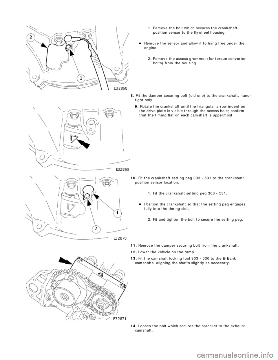
1. Remove the bolt which secures the crankshaft position sensor to the flywheel housing.
Remove the sensor and allow it to hang free under the
engine.
2. Remove the access grommet (for torque converter bolts) from the housing.
8. Fit the damper securing bolt (old one) to the crankshaft, hand-
tight only.
9. Rotate the crankshaft until the triangular arrow indent on
the drive plate is visible thro ugh the access hole; confirm
that the timing flat on ea ch camshaft is uppermost.
10. Fit the crankshaft setting peg 303 - 531 to the crankshaft
position sensor location.
1. Fit the crankshaft setting peg 303 - 531.
Position the crankshaft so that the setting peg engages
fully into the timing slot.
2. Fit and tighten the bolt to secure the setting peg.
11. Remove the damper securing bolt from the crankshaft.
12. Lower the vehicle on the ramp.
13. Fit the camshaft locking tool 303 - 530 to the B-Bank
camshafts, aligning the shafts slightly as necessary.
14. Loosen the bolt which secures the sprocket to the exhaust
camshaft.
Page 884 of 2490
2. Refit the access grommet to the housing.
13. Lower the ramp.
14. Refit the B-Bank VVT Bush Carrier Assembly. Refer to
operation 12.65.52 in this Section.
15. Refit the Timing Cover. Refer to Operation 12.65.01 in this
Section.
16. Move the engine compartment cover from the service position
and connect the gas struts.
17. Remove the paint protection sheets and close the cover.
18. Connect the battery and fit the battery cover.
Refer to the Battery Reconnection Procedure 86.15.15.
Page 886 of 2490

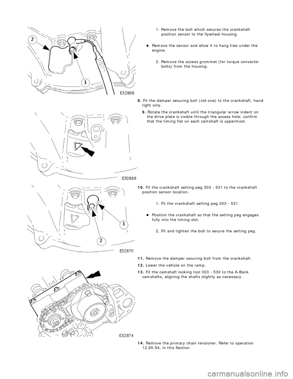
1. Remove the bolt which secures the crankshaft position sensor to the flywheel housing.
Remove the sensor and allow it to hang free under the
engine.
2. Remove the access grommet (for torque converter bolts) from the housing.
8. Fit the damper securing bolt (old one) to the crankshaft, hand-
tight only.
9. Rotate the crankshaft until the triangular arrow indent on
the drive plate is visible thro ugh the access hole; confirm
that the timing flat on ea ch camshaft is uppermost.
10. Fit the crankshaft setting peg 303 - 531 to the crankshaft
position sensor location.
1. Fit the crankshaft setting peg 303 - 531.
Position the crankshaft so that the setting peg engages
fully into the timing slot.
2. Fit and tighten the bolt to secure the setting peg.
11. Remove the damper securing bolt from the crankshaft.
12. Lower the vehicle on the ramp.
13. Fit the camshaft locking tool 303 - 530 to the A-Bank
camshafts, aligning the shafts slightly as necessary.
14. Remove the primary chain tens ioner. Refer to operation
12.65.54, in this Section
Page 889 of 2490

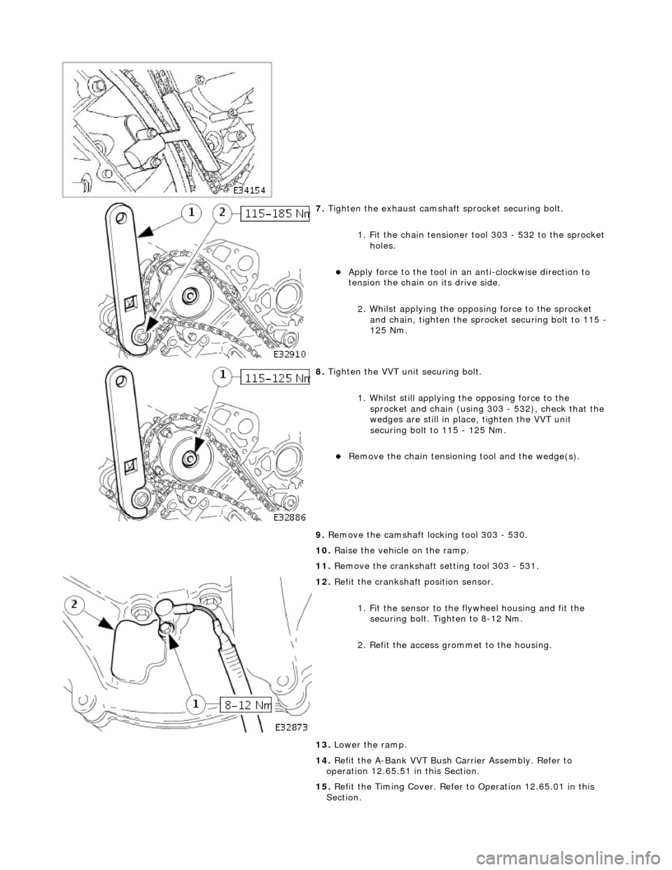
7. Tighten the exhaust camshaft sprocket securing bolt.
1. Fit the chain tensioner tool 303 - 532 to the sprocket holes.
Apply force to the tool in an anti-clockwise direction to
tension the chain on its drive side.
2. Whilst applying the opposing force to the sprocket and chain, tighten the sprock et securing bolt to 115 -
125 Nm.
8. Tighten the VVT unit securing bolt.
1. Whilst still applying the opposing force to the
sprocket and chain (using 303 - 532), check that the
wedges are still in place, tighten the VVT unit
securing bolt to 115 - 125 Nm.
Remove the chain tensioning tool and the wedge(s).
9. Remove the camshaft locking tool 303 - 530.
10. Raise the vehicle on the ramp.
11. Remove the crankshaft setting tool 303 - 531.
12. Refit the crankshaft position sensor.
1. Fit the sensor to the fl ywheel housing and fit the
securing bolt. Tighten to 8-12 Nm.
2. Refit the access grommet to the housing.
13. Lower the ramp.
14. Refit the A-Bank VVT Bush Carrier Assembly. Refer to
operation 12.65.51 in this Section.
15. Refit the Timing Cover. Refer to Operation 12.65.01 in this
Section.
Page 901 of 2490

27. Disconnect the radiator top hose.
1. Slacken the hose retaining clip and reposition the clip
along the hose.
2. Disconnect the hose from the radiator.
28. Disconnect the transmission oil cooler lower pipe.
Position a drain tray for the transmission fluid.
1. Disconnect and reposition the union nut, lower cooler pipe to radiator. Di sconnect the pipe.
2. Remove and discard the O- ring seal from the pipe
and fit blanking plugs to the pipe and to the union on
the radiator.
29. Disconnect the transmission oil cooler upper pipe.
1. Disconnect and reposition the union nut, upper cooler pipe to radiator. Di sconnect the pipe.
2. Remove and discard the O- ring seal from the pipe
and fit blanking plugs to the pipe and to the union on
the radiator.
30. Disconnect the radiator bottom hose.
1. Slacken the hose retaining clip and reposition the clip
along the hose.
2. Disconnect the hose from the radiator.
31. Release the radiator top retaining panel.
Remove the ten bolts which secure the panel.
Page 905 of 2490
Remove the bolts which secure the downpipe to the lower
mounting bracket.
Remove the downpipe assembly.
Repeat the above operations for the other downpipe
catalytic converter.
47. Remove the two bolts which secure each mounting bracket to
the bell housing and remove the brackets.
48. Disconnect the driveshaft (propshaft) flange from the
transmission output flange.
Remove the three bolts which secure the flange. Rotate
the shaft for access to each bolt.
Disconnect the shaft and reposition it to the side.
49. Remove the securing bolt and disconnect the ground lead
from the transmission casing.
50. Disconnect the oil cooler pi pes (where fitted) from the
engine.
1. Remove the bolt which secures the pipe clamping
plate. Remove the clamping plate.
2. Place a drain tray beneat h the pipes and disconnect
Page 906 of 2490

the pipes. Allow the oil to drain.
3. Remove the O-ring seals and fit blanking plugs to the
pipes and to the mating unions on the engine.
51. Lower the ramp.
52. Disconnect the generator suppres sion module (where fitted)
harness.
Disconnect the harness multi-plug and reposition the
harness from under the suppression module.
53. Disconnect the starter motor power cable, at the right hand
side engine compartment enclosure.
1. Disconnect the multi-plug, engine management harness to starter motor.
2. Reposition the protective boot from the starter motor
power stud.
3. Remove the nut and disc onnect the power cable.
Cut the tie strap which secures the power cable to the
enclosure and route the cable into the engine bay.
54. Disconnect the P.I. harness from the engine management
harness.
1. Release the bolt which secures the P.I. harness multi-plug to the engine management harness.
2. Disconnect the multi-plug.
3. Remove the nut which secures the engine management harness multi-plug to the mounting
bracket.
4. Reposition the multi-plug from the bracket.
55. Disconnect the transmission rota ry switch harness connector.
Reposition and disconnect the harness multi-plug.