1998 JAGUAR X308 electrical
[x] Cancel search: electricalPage 1970 of 2490
Interior Lighting - Vanity Mirror Lamp
Removal and Installation
Removal
Installation
1.
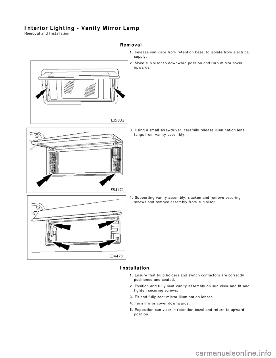
Release sun visor from retention bezel to isolate from electrical
supply.
2. Move sun visor to downward position and turn mirror cover
upwards.
3. Using a small screwdriver, carefu lly release illumination lens
tangs from vanity assembly.
4. Supporting vanity assembly, sl acken and remove securing
screws and remove assembly from sun visor.
1. Ensure that bulb holders and sw itch contactors are correctly
positioned and seated.
2. Position and fully seat vanity as sembly on sun visor and fit and
tighten securing screws.
3. Fit and fully seat mirror illumination lenses.
4. Turn mirror cover downwards.
5. Reposition sun visor in retentio n bezel and return to upward
position.
Page 1972 of 2490

Daytime Running Lamps (DRL) - Daytime Running Lamps (DRL)
Diagnosis and Testing
Tests Using the Portable Diagnostic Unit
Refer to PDU User Guide
The complexity of the electronics involved with the Body Pr ocessor and the multiplexed communication networks which are
associated with it, preclude the use of wo rkshop general electrical test equipment. Therefore, reference should be made to
the PDU User Guide for detail ed instructions on testing the Daytime Running Function.
The Daytime Running function is exactly the same as for the normal operation of the side lamps (or dipped beam, where
specified) in as much as the body processor drives the same lamps from the same outputs.
The body processor has been programmed to respond to an alternative set of cond itions in order to operate the lamps,
instead of waiting for a signal from the normal light switch.
The conditions which have to be set are; ignition switch se t to position II or III and sidelight switch set to OFF. The
sidelights, side marker lamps (if fitted and enabled), tail lights and number plate lights will all be switched ON.
The PDU systematically tests and analyses all functions of the daytime running lamps.
Where a fault is indicated, before replac ing a component, some basic diagnostic methods may be necessary to confirm that
connections are good and that wiring is not damaged.
Page 1989 of 2490
Wiring Harnesses - Wiring Harness
Description and Operation
Introduction
CAUTION: Do not use any other heat shrink sleeve other than the approved glue lined heat shrink sleeve mentioned
in the repair procedure.
The purpose of this document is to promote quick and efficient minor repair to harness connectors or cables using approved
methods and the wiring harness repair kit. Repairs may only be made to cables and connectors which have been
mechanically, not electrically damaged. It also applies wher e the whole extent of the damage can be clearly identified and
rectified.
Care and neatness are essential requir ements in making a perfect repair.
Caution:
At the time of this first issue of the Harness Repair Guide, do not approve re pairs to any of the following circuits:
Any media orientated system transport network harnesses. Supplement restraint system (SRS) firing circuits (Air bags). Link lead assembles, which are unique to safety critical circuits such as anti-lock brake system (ABS) and
thermocouple circuits. An example of this is the ABS wheel speed sensors with moulded connectors.
4. Screened cables, leads and wiring harness(s).
If any harness(s) with defective electrical connector te rminals or wires from the above circuits are a concern,
new components must be installed.
Repair Kit
CAUTION: Where the repair procedure indica tes that a glue lined heat shrink sleeve should be applied, apply sufficient
heat to the glue lined heat shrink to melt the glue in order to provide a water tight seal. Do not over heat the glue lined
heat shrink sleeve so that the wiring harness insulation becomes damaged.
The wiring harness repair kit has been produced which comprises:
Pre-terminated wiring harness(s) of different sizes and types Three sizes of butt splice connectors A selection of colored cable identification sleeves Two sizes of glue lined heat shrink sleeves Crimping pliers A wire cutter and insulation stripper An electrical connector terminal extraction handle and tips
A suitable heat source, fo r shrinking heat shrink sleeves will be required.
The pre-insulated diamond grip range of el ectrical connector terminals and in-line, butt splice connectors contained within
the wiring harness repair kit are the only acceptable product for the repairs of wi ring harnesses. The butt connectors not
only grip the wire but also the insu lation, making a very secure joint.
If an electrical connector terminal is not included in the wiring harness repair kit then approval for the repair is NOT given
and in these circumstances a new wi ring harness must be installed.
Pre-Terminated Wiring Harness( s) and Butt Splice Connectors
All pre-terminated wiring harness(s) and butt splice connectors in the wiring harness repair kit are contained in bags which
can be resealed after use. Each bag is marked with the part number of the items stored within the bag. Each storage
compartment in the wiring harness repair kit is identified with the corresponding part number. Make sure that pre-
terminated wiring harness(s) and connectors are not mixed up it is advisable to only open one bag at a time and to reseal
Page 1992 of 2490

The part number of the pre-terminated wiring harness The letter showing the extractor tip which must be used to remove this type of electrical connector terminal Those electrical connector terminals which are gold
Some of the pre-terminated wiring harness( s) have seals installed to the insulation for sealed connector applications. It is
essential for prevention of mo isture ingress that a sealed pre-terminated wiring harness must be used where a sealed
terminal was removed.
CAUTION: Where the repair procedure indica tes that a glue lined heat shrink sleeve should be applied, apply sufficient
heat to the glue lined heat shrink to melt the glue in order to provide a water tight seal. Do not over heat the glue lined
heat shrink sleeve so that the wiring harness insulation becomes damaged.
Two sizes of heat shrink sleeving are supplied in the wiring harn ess repair kit. Each heat shrink sleeve contains a sealant
glue. These must be used when connecting wiring harness(s) or electrical connector terminal(s) at all times. The smaller
diameter heat shrink sleeve is to be used with the red and blue butt splice connectors and the larger di ameter sleeve with
the yellow butt sp lice connectors.
For ease and speed, some of the pre-term inated wiring harness(s) may already have the insulation partly stripped at the
splice end. If the repair requires insula tion to be stripped from the cable, refer to the Relationship Table fo r the correct
length of insulation to be stripped.
The Pre-Terminated Wiring Harness(s) illu stration shows the electrical connector terminal type, the part number of the pre-
terminated wiring harness and the letter of the extractor tip which must be used to extract the electrical connector terminal
from the connector housing. Additionally, those electrical conne ctor terminal(s) which are gold are identified, all others are
therefore, tinned and not gold.
Wiring Harness Cable Identification Sleeves
A selection of colored sleeves are contai ned in the wiring harness repair kit for maintaining the wiring harness cable
identification on the pre-term inated wiring harness. Place the correct colo red sleeve(s) over the pre-terminated wiring
harness insulation as near to the electr ical connector as possible with the main wiring harness cable color nearest to the
electrical connector.
For example, if the original wiring harness cable color is pink with a black trace put the pink wiring harness cable
identification sleeve on the pre-terminated wiring harness first followed by a black sleeve, and slide both along the wiring
harness cable to the electr ical connector terminal.
Extraction Handle and Tips
The extraction handle, in conjunction with th e correct tip, is used to remove a terminal from an elec trical connector. Each tip contained in the wiring harness repair kit is marked with an identification letter, A to K inclusive. Each tip has been special ly
designed to extract a particular ty pe of electrical connector terminal. The use of any other tool is not recommended and is
liable to cause damage to the electrical connector. The tip is fastened to the handle by a screw which holds the tip firmly yet
allows it to be easily replaced.
Extraction Handle and Tips
Page 1996 of 2490
Items can be ordered from:
SPX United Kingdom Limited
Ironstone Way
Brixworth
Northants
NN6 9UD
United Kingdom
Telephone: +44 (0) 1327 704461
Fax: +44 (0) 1327 706632
Repair Methods
CAUTION: Several different types and sizes of terminal may be found in a single electrical connector
housing.
It is necessary to identify:
The conductor (wire) size of the affected wiring harness The electrical connector range from which the damaged wiring harness is to be removed The terminal type
Use of the approved diagnostic tool will greatly assist in th e quick identification of electrical connectors and faulty pin
terminal(s).
Reference can also be made to the vehicle Electrical Guides, he ld by Dealers, to identify wiring harness(s) and electrical
connector(s).
By using the Relationship Table, the wiring harness conductor (wire) size can be related to a suitable pre-terminated wiring
harness by the color of the insulation. Also , the correct length of insulation to be stripped from the wiring harness lead is
identified.
Relationship Table
Electrical Connector Terminal Extraction
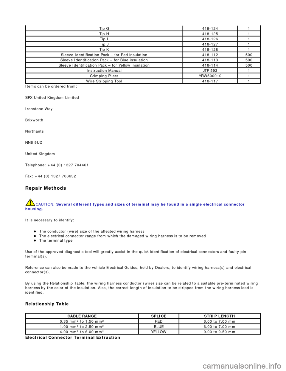
Tip G418-1241
Tip H418-1251
Tip I418-1261
Tip J418-1271
Tip K418-1281
Sleeve Identification Pa ck – for Red insulation418-112500
Sleeve Identification Pack – for Blue insulation 418-113500
Sleeve Identification Pack – for Yellow insulation 418-114500
Instruction Manual JTP 5931
Crimping Pliers YRW5000101
Wire Stripping Tool 418-1171
CABLE RANGE SPLICE STRIP LENGTH
0.35 mm² to 1.50 mm²RED6.00 to 7.00 mm
1.00 mm² to 2.50 mm²BLUE6.00 to 7.00 mm
4.00 mm² to 6.00 mm²YELLOW9.00 to 9.50 mm
Page 1997 of 2490
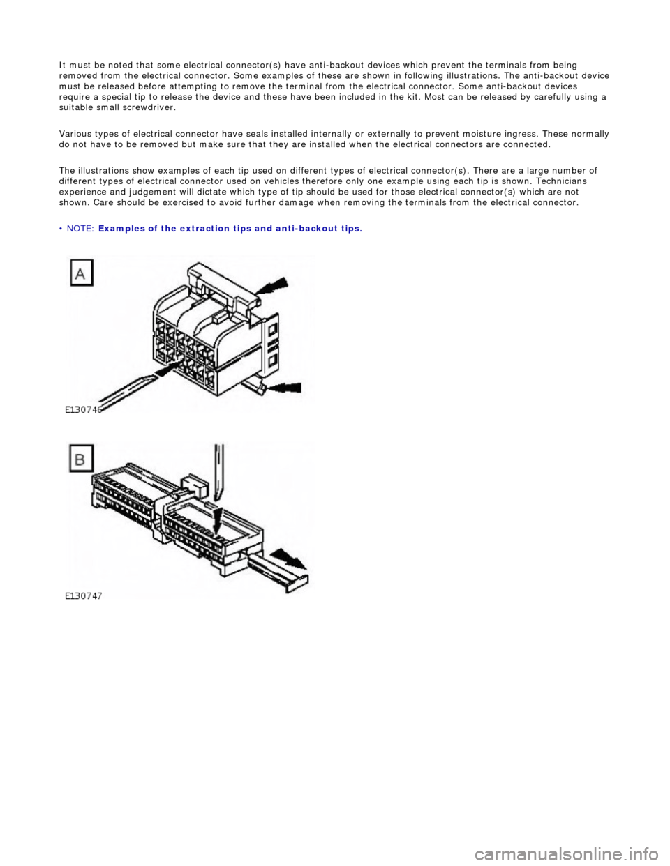
It must be noted that some electrical connector(s) have anti-backout devices which prevent the terminals from being
removed from the electrical connector. Some examples of thes e are shown in following illustrations. The anti-backout device must be released before attempting to remove the terminal from the electrical connector. Some anti-backout devices
require a special tip to release the device and these have been included in the kit. Most can be released by carefully using a
suitable small screwdriver.
Various types of electrical connector have seals installed intern ally or externally to prevent moisture ingress. These normally
do not have to be removed but make sure that they are installed when the electrical connectors are connected.
The illustrations show examples of each tip used on different types of electrical connector(s). There are a large number of
different types of electrical connector us ed on vehicles therefore only one example using each tip is shown. Technicians
experience and judgement will dictate whic h type of tip should be used for those electrical connector(s) which are not
shown. Care should be exercised to av oid further damage when removing the te rminals from the electrical connector.
• NOTE: Examples of the extraction tips and anti-backout tips.
Page 2001 of 2490
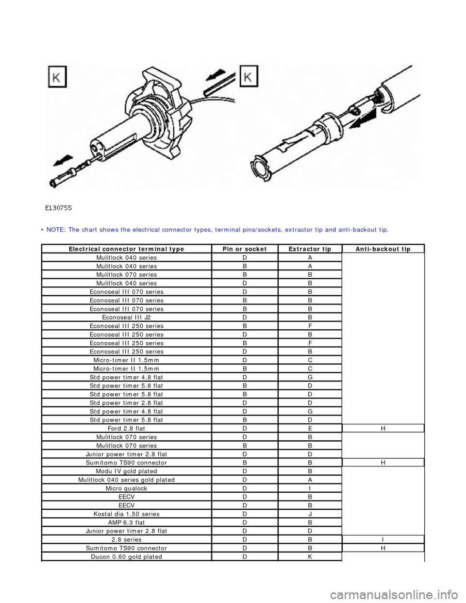
• NOTE: The chart shows the electrical connector types, terminal pins/sockets, extractor tip and anti-backout tip.
Electrical connector terminal typePin or socketExtractor tipAnti-backout tip
Mulitlock 040 seriesDA
Mulitlock 040 seriesBA
Mulitlock 070 seriesBB
Mulitlock 040 seriesDB
Econoseal III 070 seriesDB
Econoseal III 070 seriesBB
Econoseal III 070 seriesBB
Econoseal III J2DB
Econoseal III 250 seriesBF
Econoseal III 250 seriesDB
Econoseal III 250 seriesBF
Econoseal III 250 seriesDB
Micro-timer II 1.5mmDC
Micro-timer II 1.5mmBC
Std power timer 4.8 flatDG
Std power timer 5.8 flatBD
Std power timer 5.8 flatBD
Std power timer 2.8 flatDD
Std power timer 4.8 flatDG
Std power timer 5.8 flatBD
Ford 2.8 flatDEH
Mulitlock 070 seriesDB
Mulitlock 070 seriesBB
Junior power timer 2.8 flatDD
Sumitomo TS90 connectorBBH
Modu IV gold platedDB
Mulitlock 040 series gold platedDA
Micro qualockDI
EECVDB
EECVDB
Kostal dia 1.50 seriesDJ
AMP 6.3 flatDB
Junior power timer 2.8 flatDD
2.8 seriesDBI
Sumitomo TS90 connectorDBH
Ducon 0.60 gold platedDK
Page 2002 of 2490
Repair Procedure
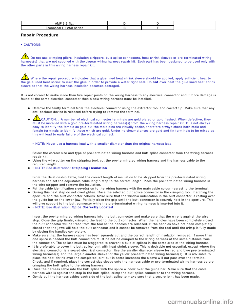
• CAUTIONS: Do not use crimping pliers, insulation strippers, butt splice connectors, heat sh rink sleeves or pre-terminated wiring
harness(s) that are not supplied with the Jagu ar wiring harness repair kit. Each part has been designed to be used only with
the other parts in this wiri ng harness repair kit.
Where the repair procedure indicates that a glue lined heat shrink sleeve should be applied, apply sufficient heat to
the glue lined heat shrink to melt the glue in order to provide a water tight seal. Do not
over heat the glue lined heat shrink sleeve so that the wiring harness insulation becomes damaged.
It is not correct to make more than five repair joints on the wiring harness to any electrical connector and if more damage is
found at the same electrical connector then a new wiring harness must be installed.
Remove the faulty terminal from the elec trical connector using the extractor tool and correct tip. Make sure that any
anti-backout device is released befo re trying to remove the terminal.
CAUTION: : A number of electrical connector terminals ar e gold plated or gold flashed. When defective, they
must be installed with a gold pre-terminated wiring harnes s(s) from the wiring harness repair kit. It is not always
easy to identify the female as gold but the male pins are visually easier, therefore always check both male and
female terminals to identify those which are gold. Under no circumstances are gold and tin terminals to be mixed as
this will lead to early failur e of the electrical contact.
• NOTE: Never use a harness lead with a smalle r diameter than the original harness lead.
Select the correct size and ty pe of pre-terminated wiring harness and butt splice connector from the wiring harness
repair kit.
Using the wire cutter on the stripping tool, cut the pre-terminated wiring harness and the harness cable to the
required length.
• NOTE: See illustration: Stripping Insulation
From the Relationship Table, find the correct length of insulation to be stripped from the pre-terminated wiring
harness and set the adjustable cable length stop to the correct length. Place the pre-terminated wiring harness in
the wire stripper and remove the insulation.
Put the cable identification sleeve(s) on to the wiring harness with the main cable colour nearest to the terminal. During this next step do not overtighten. Place the selected butt splice connector in the crimping tool, matching the
aperture and the butt connector colours. Make sure that the window indentation in the butt connector is resting over
the guide bar on the lower jaw. Partially close the grip until the butt connec tor is securely held in the aperture. This
will give support to the butt conn ector while the pre-terminated wiring harness is inserted into it.
• NOTE: See illustration: Spice Correctly Located
Insert the pre-terminated wiring harnes s into the butt connector and make sure that the wire is against the wire
stop. Close the grip firmly, crimping the lead to the butt connector. When the handles have been completely closed
the butt connector will be fre ed from the tool as the handles are released. If the handles have not been completely
closed then the jaws will hold the butt connector and it cannot be removed from the tool until the crimp is fully made
by closing the handles completely. Make sure that the harness cable has been squarely cut and the correct length of insulation removed. If more than
one splice is needed the butt connectors must be not be crimped to the wiring harness at the same distance from
the connector. The splices must be staggered to prevent a bulk of splices in the same area of the wiring harness.
It is preferable to cover the butt splice joint with heat shrink sleeve. This is desirable not essential, except where the
electrical connector is a sealed electrical connector. Use the smaller diameter sleeve for red and blue pre-terminated
wiring harness(s) and the large diameter sleeve for the yellow pre-terminated wiring harnes s(s). It is advisable to
place the heat shrink over the completed joint but in some instances the sleeve will not pass over the terminal.
Check, and if required, place the correct size sleeve onto the harness cable or pre-terminated wiring harness before
crimping the butt splice to the wiring harness.
Place the harness cable into the butt splice with the spli ce window over the guide bar. Make sure that the cable
harness wire is agains t the stop in the butt splice, crimp the butt splice connector to the wiring harness.
Gently pull the harness cables each side of the butt sp lice to make sure that a secure joint has been made.
AMP 6.3 flatDD
Econoseal III 250 seriesBF