Page 1908 of 2490
Antenna - Antenna
Description and Operation
The electrically operated antenna operates automatically when the Ignition switch is set to position 1 or 2, and the radio
cassette player is switched on , regardless of the status of the tape or CD mode switch.
The antenna motor is protected by a 10A fuse, F9, located in the trunk fuse-box.
Page 1920 of 2490

Direction indicator and side marker lamps
Each front direction indicator and side marker lamp is retained in the bumper cover by a lug at one end and a spring clip at
the other end. The side marker lamps are not electrically connected for certain markets.
The side repeater lamps are secured by sp ring clips on the lower edge of the lamp unit. In certain markets Jaguar leaper
badges are substituted for side repeater lamps.
Fog lamps
The fog lamps are located in recesses in the front bump er and secured by three screws. The la mps which are not
interchangeable left to right, are accessed from the rear of the bumper.
Operation
All lamps are controlled by the BPM which provides an appropriate output in response to an input received when a selected
switch is operated.
All lamps receive an input direct from th e BPM with the exception of the main be am, dip beam and front fog lamps which
receive an input from the BPM vi a the respective relays and fuses; refer to section 418-01.
Fault analysis must be undertaken using the PDU. Refer to Diagnosis and Testing.
Consult the relevant Electrical Guid e for details of circuit operation.
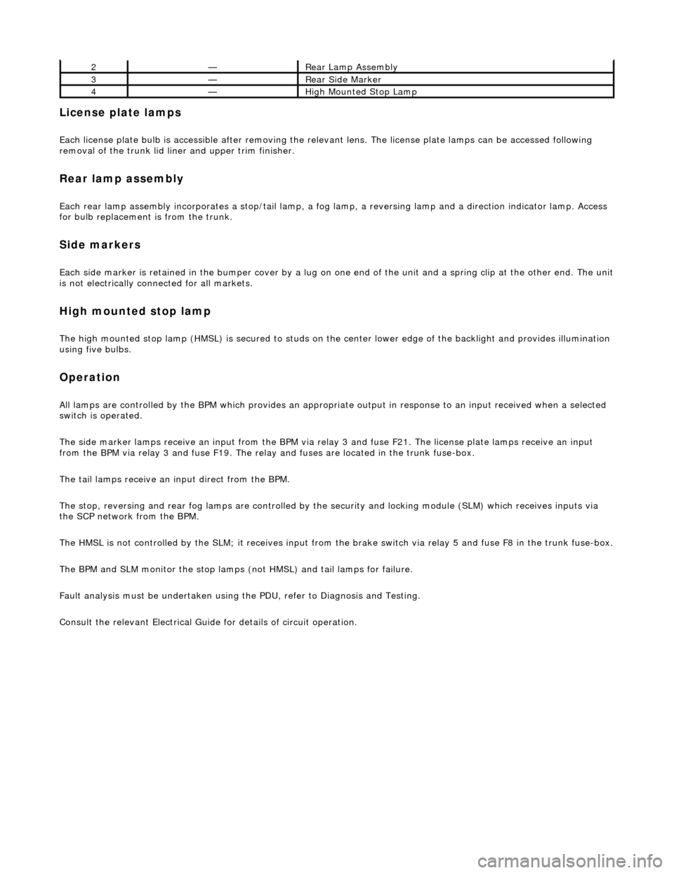
Rear Lamps
ItemPart NumberDescription
1—License Plate Lamps
Page 1921 of 2490

License plate lamps
Each license plate bulb is accessible after removing the relevant lens. The license plate lamps can be accessed following
removal of the trunk lid liner and upper trim finisher.
Rear lamp assembly
Each rear lamp assembly incorporates a stop/tail lamp, a fog lamp, a reversing lamp and a direction indicator lamp. Access
for bulb replacement is from the trunk.
Side markers
Each side marker is retained in the bumper cover by a lug on one end of the unit and a spring clip at the other end. The unit is not electrically connected for all markets.
High mounted stop lamp
The high mounted stop lamp (HMSL) is secu red to studs on the center lower edge of the backlight and provides illumination
using five bulbs.
Operation
All lamps are controlled by the BPM which pr ovides an appropriate output in response to an input received when a selected
switch is operated.
The side marker lamps receive an input from the BPM via relay 3 and fuse F21. The license plate lamps receive an input
from the BPM via relay 3 and fuse F19. The rela y and fuses are located in the trunk fuse-box.
The tail lamps receive an input direct from the BPM.
The stop, reversing and rear fog lamps are controlled by the security and locking module (SLM) which receives inputs via
the SCP network from the BPM.
The HMSL is not controlled by the SLM; it receives input from the brake switch via relay 5 and fuse F8 in the trunk fuse-box.
The BPM and SLM monitor the stop lamps (n ot HMSL) and tail lamps for failure.
Fault analysis must be undertaken using the PDU, refer to Diagnosis and Testing.
Consult the relevant Electrical Guid e for details of circuit operation.
2—Rear Lamp Assembly
3—Rear Side Marker
4—High Mounted Stop Lamp
Page 1922 of 2490

Exterior Lighting - Exterior Lighting
Diagnosis and Testing
Tests Using the Portable Diagnostic Unit
Refer to PDU User Guide
The complexity of the electronics involved with the various Electronic Control Modules and the multiplexed communication
networks, preclude the use of workshop general electrical test equipment. Therefore, reference should be made to the PDU
User Guide for detailed inst ructions on testing the exterior lamps and circuits.
The PDU systematically tests and analyses the lamp assemblies, the bulbs and the electrical connections to them. It should
be noted that the lamps are not wired direct ly to the switches. Actuation of a switch provides an input signal to the Body
Processor which interpre ts the signal as a request to switch output from the Bo dy Processor, either directly or indirectly to a
specific lamp.
Where a fault involving a lamp is indicated by the PDU, befo re replacing the component, some basic diagnostic methods
may be necessary to confirm that connections are good and that wiring is not damaged.
Page 1923 of 2490
Exterior Lighting - Brake Pedal Position (BPP) Switch
Removal and Installation
Removal
Installation
1. Disconnect the brake pedal posi tion (BPP) switch electrical
connector.
2. Remove the BPP switch.
1. Press and hold down the brake pedal.
2. CAUTIONS:
Make sure the brake pedal is held clear of the BPP switch
ratchet mechanism during installation. Failure to follow this
instruction may result in incorrect adjustment of the BPP switch.
Make sure the BPP sw itch is correctly installed to the upper
locating point.
Install the BPP switch. 1. Align the BPP switch to the upper locating point.
2. Install the BPP switch.
3. Release the brake pedal.
4. CAUTION: Make sure the br ake pedal is fully raised.
Failure to follow this instru ction may result in incorrect
adjustment of the BPP switch.
Fully raise the brake pedal.
Page 1924 of 2490
5. Connect the BPP switch electrical connector.
Page 1963 of 2490

Rear courtesy/ reading lamps
Each rear quarter of the passenger compartment is fitted with combined lighting units comprising; a rear courtesy lamp and
reading lamp. The courtesy lamps operate automatically whenever a rear door is opened; the reading lamps function when
the integral switches are operated by occupants of the vehicle.
Trunk lamps
The trunk trim panel is fitted with lamps which operate auto matically whenever the trunk lid is opened; the switch is
incorporated within the latch mechanism.
Vanity mirror lamps
The vanity mirror lamps, two on each sun visor, operate auto matically when the mirror flap is opened, provided the sun
visor spindle is engage d in the stowage clip.
Operation
The BPM provides an enable signal for the glovebox, vanity mirror, trunk lid and map lamps. Actuation of the relevant
switch provides an earth path to the lamp.
The rear passenger reading lamps receive a supply di rect from fuse F10 in the RH heelboard fuse-box.
The front and rear courtesy lamps have separa te fade functions controlled by the BPM.
The door hazard / puddle lamps are controll ed locally by the relevant Door Module.
Fault analysis must be undertaken using the PDU, refer to Diagnosis and Testing.
Refer to the relevant Electrical Guid e for details of circuit operation.
Page 1964 of 2490

Interior Lighting - Interior Lighting
Diagnosis and Testing
Tests Using the Portable Diagnostic Unit
Refer to PDU User Guide
The complexity of the electronics involved with the various Electronic Control Modules and the multiplexed communication
networks, preclude the use of workshop general electrical test equipment. Therefore, reference should be made to the PDU
User Guide for detailed inst ructions on testing the interior lamps and circuits.
The PDU systematically tests and analyses the lamp assemblies, the bulbs and the electrical connections to them. It should
be noted that the lamps are not wired directly to the switches.
The lamps are controlled directly by the Bo dy Processor (it has a sufficient number of high power output stages to drive the
lamps / relays compared to other module s) except for the door guard / puddle lamps and the rear passenger reading lamps.
The Body Processor Module receives messages on the SCP network from the door modules relating to door ajar / closed /
locked status, sensed by the door courtesy switch(es).
Where a fault involving a lamp is indicated by the PDU, be fore replacing suspect components, some basic diagnostic
methods may be necessary to confirm that connecti ons are good and that wiring is not damaged.