Page 2171 of 2490
Seating - Rear Seat Cushion Heater Mat
Removal and Installation
Removal
Installation
1.
Remove the rear seat cushion. Fo r additional information, refer
to the procedure in this section: Rear Seat Cushion
.
2. Remove the seat cushion cover.
3. Detach the seat cushion heater element electrical connectors.
4. Remove the seat cushion heater element.
1. To install, reverse the removal procedure.
Page 2179 of 2490

Glass, Frames and Mechanisms - Glass, Frames and Mechanisms
Description and Operation
Fixed Glass
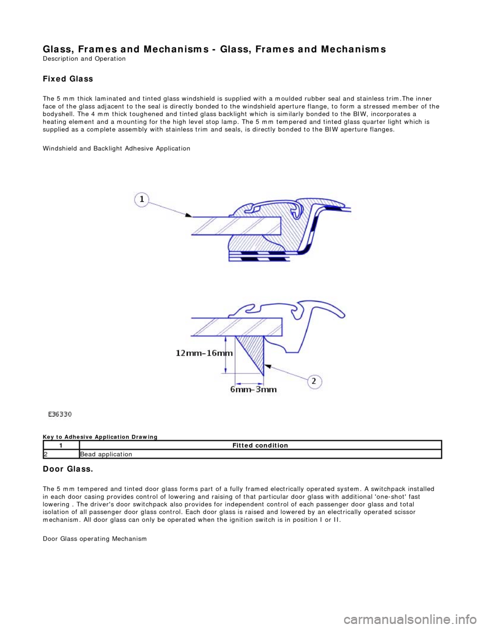
The 5 mm thick laminated and tinted glas s windshield is supplied with a moulded rubber seal and stainless trim.The inner
face of the glass adjacent to the seal is directly bonded to the windshield aperture flange, to form a stressed member of the
bodyshell. The 4 mm thick toughened and tinted glass backlight which is similarly bonded to the BIW, incorporates a
heating element and a mounting for the high level stop lamp. The 5 mm tempered and tinted glass quarter light which is
supplied as a complete assembly with stainless trim and seals, is directly bonded to the BIW aperture flanges.
Windshield and Backlight Adhesive Application
Key to Adhesive Application Drawing
Door Glass.
The 5 mm tempered and tinted door glass forms part of a fully framed electrically operated system. A switchpack installed
in each door casing provides control of lowering and raising of that particular d oor glass with additional 'one-shot' fast
lowering . The driver's door switchpack also provides for independent control of each passenger door glass and total
isolation of all passenger door glass control. Each door glas s is raised and lowered by an electrically operated scissor
mechanism. All door glass can only be operated wh en the ignition switch is in position I or II.
Door Glass operating Mechanism
1Fitted condition
2Bead application
Page 2205 of 2490
2. Remove the rear window finisher.
3. Apply protective tape around rear window glass aperture.
4. Remove the high mounted stoplamp.
For additional information, refer to: High Mounted Stoplamp
(417-01 Exterior Lighting, Removal and Installation).
5. Remove both C-pill ar trim panels.
For additional information, refer to: C
-Pillar Trim Panel (501-05
Interior Trim and Ornamentatio n, Removal and Installation).
6. Remove the parcel shelf.
For additional information, refer to: Parcel Shelf
(501-05
Interior Trim and Ornamentatio n, Removal and Installation).
7. NOTE: Right-hand shown, left-hand similar.
Disconnect the electrical connector.
Page 2206 of 2490
8. Disconnect the radio antenn a electrical connector.
9. Apply suitable protec tive tape to the upper edge of the
headlining.
10. Prepare cheese wire and cutting handle.
Position cutting handle cent ral tube fully upwards in
handle.
Cut a suitable length of ch eese wire and pass one end
through handle tube and locating aperture.
Move cutting handle central tube downwards to secure
cheese wire.
11. Using a suitable long bladed tool, penetrate the rear window
adhesive approximately 150mm fro m the top of one rear pillar.
Page 2210 of 2490

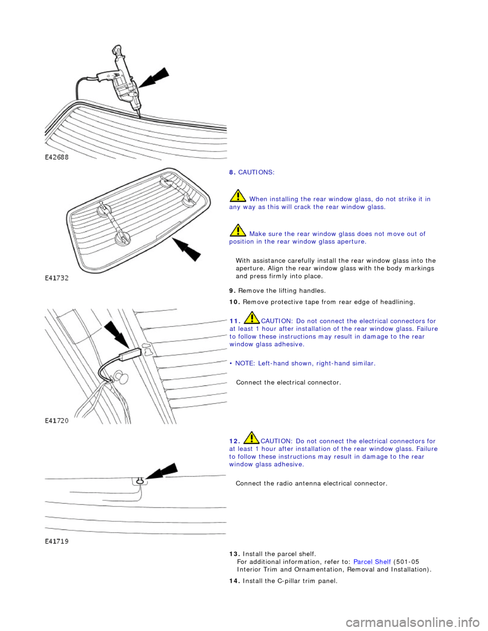
8. CAUTIONS:
When installing the rear window glass, do not strike it in
any way as this will crac k the rear window glass.
Make sure the rear window glass does not move out of
position in the rear window glass aperture.
With assistance carefully install the rear window glass into the
aperture. Align the rear window glass with the body markings
and press firmly into place.
9. Remove the lifting handles.
10. Remove protective tape from rear edge of headlining.
11. CAUTION: Do not connect the electrical connectors for
at least 1 hour after installation of the rear window glass. Failure
to follow these instructions may result in damage to the rear
window glass adhesive.
• NOTE: Left-hand shown, right-hand similar.
Connect the electrical connector.
12. CAUTION: Do not connect the electrical connectors for
at least 1 hour after installation of the rear window glass. Failure
to follow these instructions may result in damage to the rear
window glass adhesive.
Connect the radio antenna electrical connector.
13. Install the parcel shelf.
For additional information, refer to: Parcel Shelf (501-05
Interior Trim and Ornamentatio n, Removal and Installation).
14. Install the C-pillar trim panel.
Page 2277 of 2490
Handles, Locks, Latches and Entry Systems - Exterior Driver Door Handle
Removal and Installation
Removal
1. Motor door glass to fully up position.
2. Remove battery cover and disconnect ground cable from
battery terminal. Refer to 86.15.19.
3. Remove door casing veneer panel. Refer to 76.47.11.
4. Remove door casing for access. Refer to 76.34.01.
5. Feeding electrical harness thro ugh water shedder, carefully
peel shedder from door and pl ace adhesive face down on a
clean dry polythene sheet.
6. Position PVC inner sheet for access.
7. Disconnect outer handle link rod from lock assembly.
8. Slacken and remove outer handle rear securing bolt.
9. Slacken and remove security gu ard lower securing bolt and
remove guard from door.
Page 2297 of 2490
Handles, Locks, Latches and Entry Systems - Exterior Passenger Door
Handle
Removal and Installation
Removal
1. Remove battery cover and disconnect ground cable from
battery terminal. Refer to 86.15.19.
2. Remove door casing veneer panel. Refer to 76.47.11.
3. Remove door casing for access. Refer to 76.34.01.
4. Feeding electrical harness thro ugh water shedder, carefully
peel shedder from door and pl ace adhesive face down on a
clean dry polythene sheet.
5. Position PVC inner sheet for access.
6. Disconnect door handle operating link rod from lock
assembly.
7. Slacken and remove the two handle mounting bracket
securing bolts and remove bracket from door.
8. Withdraw handle assembly from door and remove link rod
from handle.
Page 2328 of 2490

Roof Opening Panel - Roof Opening Panel
Description and Operation
General Description
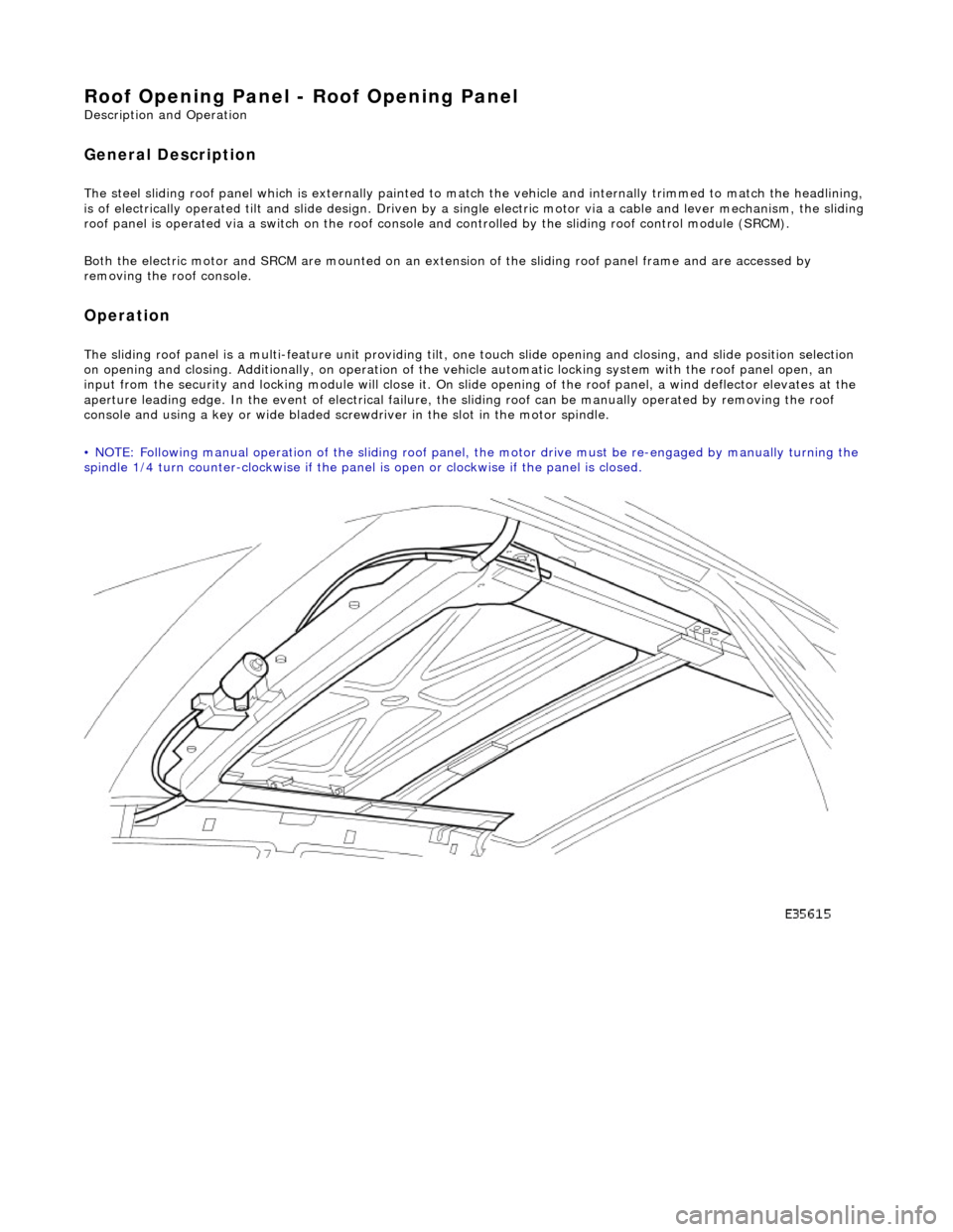
The steel sliding roof panel which is externally painted to ma tch the vehicle and internally trimmed to match the headlining,
is of electrically operated tilt and slide design. Driven by a single electric motor via a cable and lever mechanism, the slidi ng
roof panel is operated via a switch on the roof console and controlled by the sliding roof control module (SRCM).
Both the electric motor and SRCM are mounted on an extens ion of the sliding roof panel frame and are accessed by
removing the roof console.
Operation
The sliding roof panel is a multi-feature unit providing tilt, one touch slide opening and closing, and slide position selectio n
on opening and closing. Additi onally, on operation of the vehicle automatic locking system with the roof panel open, an
input from the security and lockin g module will close it. On slide opening of the roof panel, a wind deflector elevates at the
aperture leading edge. In the event of electrical failure, the sliding roof can be manually operated by removing the roof
console and using a key or wide bladed scre wdriver in the slot in the motor spindle.
• NOTE: Following manual operation of the sliding roof panel, the motor drive must be re-engaged by manually turning the
spindle 1/4 turn counter-clockwise if the panel is open or clockwise if the panel is closed.