Page 1870 of 2490
Parking Aid - Parking Aid
Diagnosis and Testing
Inspection and Verification
1.1. Verify the customer concern.
2. 2. Visually inspect for obvious signs of mechanical or electrical damage.
Visual Inspection Chart
3. 3. If an obvious cause for an observed or reported concern is found, correct the cause (if possible) before proceeding to the next step
4. 4. If the cause is not visually evident, verify the sympto m and refer to the Jaguar approved diagnostic system.
Electrical
Fuse(s) Relay(s) Wiring Harness Electrical connector(s) Rear parking aid sensor(s) Rear parking aid speaker Reversing lamp switch Parking aid module
Page 1872 of 2490
Installation
Disconnect the electrical connectors.
1. To install, reverse the removal procedure.
Page 1873 of 2490
Parking Aid - Rear Parking Aid Sensor
Removal and Installation
Removal
Installation
1.
Raise and support the vehicle.
For additional information, refer to: Jacking
(100-02 Jacking
and Lifting, Descript ion and Operation).
2. Disconnect the electrical connector.
3. CAUTION: Make sure excessiv e pressure or tools are not
used when removing the parkin g aid sensor from the housing.
Remove the rear parking aid sensor.
1. To install, reverse the removal procedure.
Page 1874 of 2490
Parking Aid - Rear Parking Aid Speaker
Removal and Installation
Removal
Installation
1.
Remove the parcel shelf.
For additional information, refer to: Parcel Shelf
(501-05
Interior Trim and Ornamentatio n, Removal and Installation).
2. Reposition the sound insulation.
3. Disconnect the electrical connector.
4. Remove the rear parking aid speaker.
1. To install, reverse the removal procedure.
Page 1882 of 2490

Generator and Regulator - Generator
Description and Operation
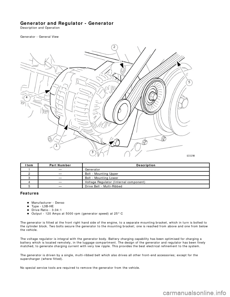
Generator - General View
Features
Manufacturer - Denso Type - L3B-HE Drive Ratio - 3.04:1 Output - 120 Amps at 5000 rpm (generator speed) at 25° C
The generator is fitted at the front right hand side of the engine, to a sepa rate mounting bracket, which in turn is bolted to
the cylinder block. Two bolts secure th e generator to the mounting bracket; one is reached from above and one from below
the vehicle.
The voltage regulator is integral with th e generator body. Battery charging capabi lity has been optimised for charging a
battery which is located remotely, in the luggage compartment. The design of the generator and regulator has been finely
matched, to generate charging current with very low ripple. This provides the best electrical refinement to the system.
The generator is driven by a single, multi-ribbed belt which also drives all other front-e nd accessories; except for the
supercharger (where fitted).
No special service tools are required to remove the generator from the vehicle.
ItemPart NumberDescription
1—Generator
2—Bolt - Mounting Upper
3—Bolt - Mounting Lower
4—Voltage Regulator (Internal component)
5—Drive Belt - Multi-Ribbed
Page 1887 of 2490

Generator and Regulator - Generator
Diagnosis and Testing
Refer to PDU User Guide
Refer to the PDU User Manual for detailed instructions on testing the charging circuit.
When diagnosing the charging ci rcuit, the PDU indicates only whether the generator is charging or not charging. The reason
for this is that the PDU cannot handle the potential full charging current and that the voltage control circuits are located
within the generator assembly, making th em inaccessible by the PDU directly.
It is possible that the battery has failed. In this case, the voltage output at the generator could be correct, but the voltage
at the battery terminals, and therefore the rest of the vehicl e system, will be adversely affected by the faulty battery.
The same result is given by the PDU if the battery is faulty (generator not faulty), wiring fault (damaged or severe corrosion
at the terminals) or if th e generator is at fault.
Inspection and Verification
The following manual tests help to pinpoint which component is at fault.
Testing the Battery Circuit
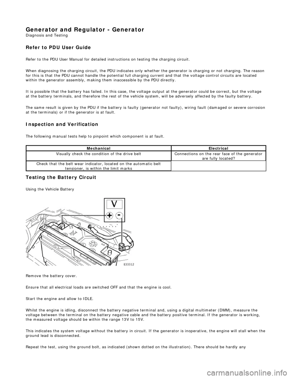
Using the Vehicle Battery
Remove the battery cover.
Ensure that all electrical loads are swit ched OFF and that the engine is cool.
Start the engine and allow to IDLE.
Whilst the engine is idling, disconnect the battery negative terminal and, using a digital multimeter (DMM), measure the
voltage between the terminal on the batter y negative cable and the battery positive terminal. If the generator is working,
the measured voltage should be within the range 13V to 15V.
This indicates the system voltage without the battery in circuit. If the generator is inoperative, the engine will stall when t he
ground lead is disconnected.
Repeat the test, using the ground bolt, as indicated (shown dotted on the illustration). There should be hardly any
MechanicalElectrical
Visually check the condition of the drive beltConnections on the rear face of the generator
are fully located?
Check that the belt we ar indicator, located on the automatic belt
tensioner, is within the limit marks
Page 1888 of 2490

detectable difference in the voltage reading (due to minimal current flow); if there is a detectable difference, clean the cable terminal and the adjacent area of the body.
When the voltage has been measured, STOP THE ENGINE.
Reconnect the battery or fit a new battery if it was established that the battery was at fault (Refer to 414-01).
If the cooling fans operate during the above test, the large demand of current will overload the generator and cause the
engine to stall.
If the battery is in a low state of charge the voltage will rise momentarily when the battery is disconnected. However, the
maximum that the voltage can increase to with this new gene rator is 25V and then only for a maximum time of 200 mS.
Using a Substitute Battery
A substitute battery may be fitted for the tests. This batter y must be a known good example and must have been off-charge for at least twelve hours, with a term inal voltage of approximately 12.8V.
Ensure that all electrical loads are swit ched OFF and that the engine is cool.
Start the engine and allow to IDLE.
Measure the voltage across the battery term inals. It should have dropped a little due to the large start current and then
risen to a value of between 13V and 15V.
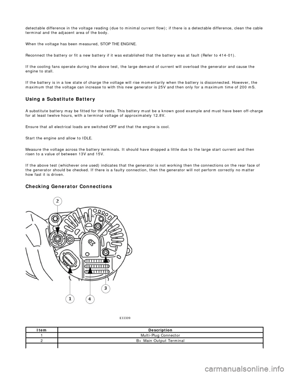
If the above test (whichever one used) indicates that the generator is not working then the connections on the rear face of
the generator should be checked. If there is a faulty connection, then the ge nerator will not perform correctly no matter
how fast it is driven.
Checking Generator Connections
ItemDescription
1Multi-Plug Connector
2B+ Main Output Terminal
Page 1904 of 2490
Audio Unit - Audio System
Description and Operation
The choice of two entertainment system s is available; base or premium.
The base system comprises a radio cassette player with in tegral message display and "Phone Ready" controls for an
accessory telephone; door speakers and tweeters.
The premium system has the following additional components: power amplifier, CD autochanger, sub-woofer and 'A' post
tweeters fitted instead of front door tweeters.
Both systems can be operated remotely by use of switches loca ted on the steering wheel and have an electrically operated
aerial.
Telephone controls incorporated in the ra dio cassette unit facilitate inclusion of the GSM hands free telephone system
available as optional equipment.
After diagnostic or repair operations, refer to the Sound System Handbook for setting-up procedures and operation.