Page 1367 of 2490
Automatic Transmission/Transaxle - 4.0L NA V8 - AJ27/3.2L NA V8 - AJ26
- Transmission Internal Wiring Harnes s Electrical Connector O-Ring Seals
In-vehicle Repair
Removal
1. Disconnect battery ground cable.
Remove the battery cover.
2. Raise the vehicle for access.
3. Remove the fluid pan; refer to 44.24.04.
4. Remove selector cable abutment bracket fixings (2) and
reposition the bracket for access to the multiplug.
5. Disconnect the transmission harness multiplug.
1. Release the harness locking lever.
2. Disconnect the harness multiplug.
6. Remove harness multiplug retaining clip.
Push the multiplug into the transmission casing to release.
Discard the two 'O' rings.
Page 1390 of 2490
Stator, intermediate and output shafts. Three epicyclic geartrains. Six multi-disc clutch/brake packs. Two freewheels (One-way clutches). Hydraulic pump. Parking lock assembly. Electro-hydraulic control unit. Internal harness and 13 pin connector with bayonet lock.
Hydraulic pump
This engine driven pump is located at the front of the transmission casing and provides pressure for the hydraulic
functions.
Supplies fluid under pressure to the torq ue converter, geartrain, electro-hydraulic control unit and the lubrication
circuit.
Draws fluid from the fluid pa n below the transmission casing, through a filter.
Parking lock
This component prevents movement of th e vehicle by engaging a fixed pawl with the parking lock gear located on the
output shaft. The pawl is engaged by movi ng the gear selector lever to the park (P) position.
Electro-hydraulic control unit
This unit, mounted in the transmission lower case, converts signals, mechanical from the J-gate and electrical from the
TCM, into hydraulic functions.
The following components ar e assembled to the unit:
Selector valve. Shift plate. Control valve - modulating pressure. Control valve - shift pressure. Solenoid valve 1 <-> 2 and 4 <-> 5 shift. Solenoid valve 3 <-> 4 shift. Solenoid valve 2 <-> 3 shift. Solenoid valve - converter lock-up. Speed sensors (2). Temperature sensor.
Speed sensors
There are two speed sensors within the transmission assembly which provide input to the TCM. These inputs, when used in
conjunction with CAN data relative to engine speed (from ECM) and road speed (from ABS), are used to electronically
control the transmission.
Temperature sensor
The output from this sensor allows the TCM to compensate for the affect of fluid temperature on shift time and quality
Control Systems
Hydraulic Control
The selector valve is operated directly by the J-gate and directs fluid flow for P R N D.
Of the four solenoid valves, 3 control shifts and 1 controls converter lock-up. One control valve controls modulating pressure
and the other shift pressure.
Regulating valves are used to maintain/control pressure for lu brication, normal operating functions, and the supply to the
control valves and shift valves.
Page 1391 of 2490
In the event of a system fault, the TCM will adopt 'limp home' mode.
Electrical control
Refer to Section 307-01B.
Transmission Control Components
Transmission Control Module (TCM)
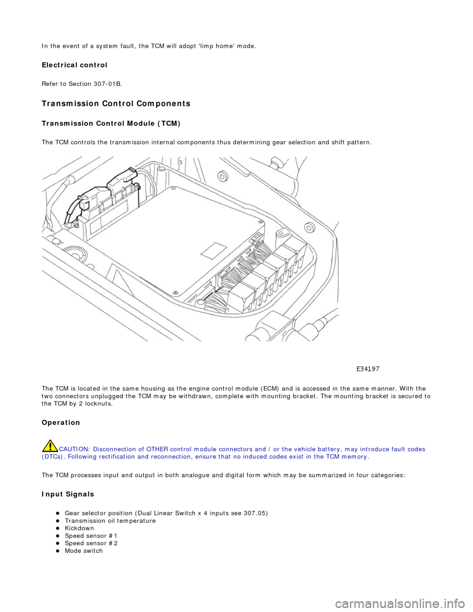
The TCM controls the transmission internal components thus determining gear selection and shift pattern.
The TCM is located in the same housing as the engine control module (ECM) and is accessed in the same manner. With the
two connectors unplugged the TCM may be withdrawn, complete with mounting bracket. The mounting bracket is secured to
the TCM by 2 locknuts.
Operation
CAUTION: Disconnection of OTHER contro l module connectors and / or the vehicle battery, may introduce fault codes
(DTCs). Following rectification and reconnection, ensu re that no induced codes exist in the TCM memory.
The TCM processes input and output in both analogue and di gital form which may be summarized in four categories:
Input Signals
Gear selector position (Dual Linear Switch x 4 inputs see 307.05) Transmission oil temperature Kickdown Speed sensor #1 Speed sensor #2 Mode switch
Page 1393 of 2490
2.2. Switch OFF the ignition.
3. 3. Wait 10 seconds.
4. 4. Start the engine.
5. 5. Select R (reverse will be selected).
6. 6. Select D ( 2 will be selected).
The limp-home mode will be retained until the fault is remedied or the fault code has been erased. Intermittent faults may
be cleared by cycling the ignition OFF/ON. In certain cases the component may need to be operated before the fault code is
cleared eg. a shift solenoid.
Emergency Running (mechanica l/hydraulic limp-home mode)
Should slip be detected, due to a mechanical failure or loss of pressure, the transmission will either shift to, and hold 3 or
shift to, and hold, the last gear which was known to be alright. This condition may be cleared by cycling the ignition OFF/ON
following mechanical repair.
The operator will be made aware of certain faults by a warning message on th e instrument cluster.
Data concerning OBDII related transmission failures is stored in the ECM for access via the J1962 socket.
Safety Functions
These functions are designed to safeguard against inappropriate actions by the operator as well as system malfunctions.
The electrical and diagnostic system has been designed such that system integrity is protected at all times, the safety
concept being based on th e following three points.
1. 1. The hydraulic system has 'fail-safe' characteristics regardin g its electrical operation, such that should the power
supply be lost to the electro-hydraulic actuators the transmission will initiate a limp-home mode.
2. 2. Recognition of critical shift operation by monitoring the last element in the signal path, ie the solenoid valve, and
checking by means of redundant me asured variables relative to engine, transmission and road speeds.
3. 3. Each time the vehicle is started there is a check on the entire safety hardware and the associated program parts
and signal paths. A malfunction in this part of the system, or triggering of the safety circuit, is communicated to
the operator by a warning messag e on the instrument cluster.
CAUTION: Do not engage R or P with the vehicle in motion.
Should R be engaged with the vehicle in forward motion, the transmission will default to neutral until either the vehicle
speed decreases to 4 mph or D is selected.
Towing
The vehicle may be towed provided that:
Selector in position N Speed < 50 kph Distance < 50 km
System Functions
'J' Gate Layout
Page 1400 of 2490
Automatic Transmission/Transaxle - 4.0L SC V8 - AJ26 - Diagnostic
Strategy
Diagnosis and Testing
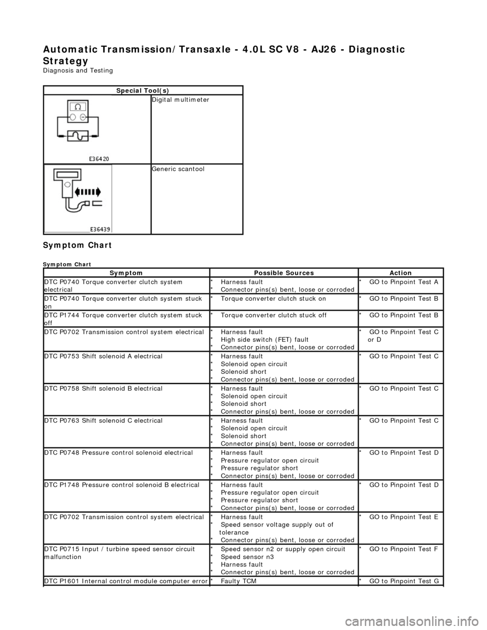
Symptom Chart
Symptom Chart
Special Tool(s)
Digital multimeter
Generic scantool
SymptomPossible SourcesAction
DTC P0740 Torque converter clutch system
electricalHarness fault
Connector pins(s) bent , loose or corroded
*
*GO to Pinpoint Test A
*
DTC P0740 Torque converter clutch system stuck
onTorque converter clutch stuck on
*GO to Pinpoint Test B
*
DTC P1744 Torque converter clutch system stuck
offTorque converter clutch stuck off
*GO to Pinpoint Test B
*
DTC P0702 Transmission control system electricalHarness fault
High side switch (FET) fault
Connector pins(s) bent , loose or corroded
*
*
*GO to Pinpoint Test C
or D
*
DTC P0753 Shift solenoid A electricalHarness fault
Solenoid open circuit
Solenoid short
Connector pins(s) bent
, loose or corroded
*
*
*
*GO to Pinpoint Test C *
DTC P0758 Shift solenoid B electricalHarness fault
Solenoid open circuit
Solenoid short
Connector pins(s) bent
, loose or corroded
*
*
*
*GO to Pinpoint Test C *
DTC P0763 Shift solenoid C electricalHarness fault
Solenoid open circuit
Solenoid short
Connector pins(s) bent
, loose or corroded
*
*
*
*GO to Pinpoint Test C *
DTC P0748 Pressure control solenoid electricalHarness fault
Pressure regulator open circuit
Pressure regulator short
Connector pins(s) bent
, loose or corroded
*
*
*
*GO to Pinpoint Test D *
DTC P1748 Pressure control solenoid B electricalHarness fault
Pressure regulator open circuit
Pressure regulator short
Connector pins(s) bent
, loose or corroded
*
*
*
*GO to Pinpoint Test D *
DTC P0702 Transmission control system electricalHarness fault
Speed sensor voltage supply out of
tolerance Connector pins(s) bent , loose or corroded
*
*
*GO to Pinpoint Test E
*
DTC P0715 Input / turbine speed sensor circuit
malfunctionSpeed sensor n2 or supply open circuit
Speed sensor n3
Harness fault
Connector pins(s) bent , loose or corroded
*
*
*
*GO to Pinpoint Test F
*
DTC P1601 Internal control module computer errorFaulty TCM
*GO to Pinpoint Test G *
Page 1438 of 2490
Installation
13. Remove the valve body assembly.
Remove the nine bolts which re tain the valve body to the
transmission case.
1. Installation is the re verse of the removal procedure, noting the
following:
2. Clean all mating faces and relevant parts.
3. Tighten the nine bolts securing the valve body, to the specified
torque figure.
4. Refit the dowel (leaf spring to valve body) and the leaf spring.
Fit and tighten the securing bolt to the specified torque figure.
5. Tighten the centre retaining bolt of the electrical connector to
the specified torque figure.
Page 1445 of 2490
4. Tighten the centre retaining bolt of the electrical connector
guide bush to 2.25 to 2.75 Nm.
5. Perform the Battery Reconnection Procedure described in
Operation 86.15.15.
6. Refer to Operation 44.24.02 for fluid fill procedure.
7. Check for leaks and remove spilt fluid.
Page 1518 of 2490
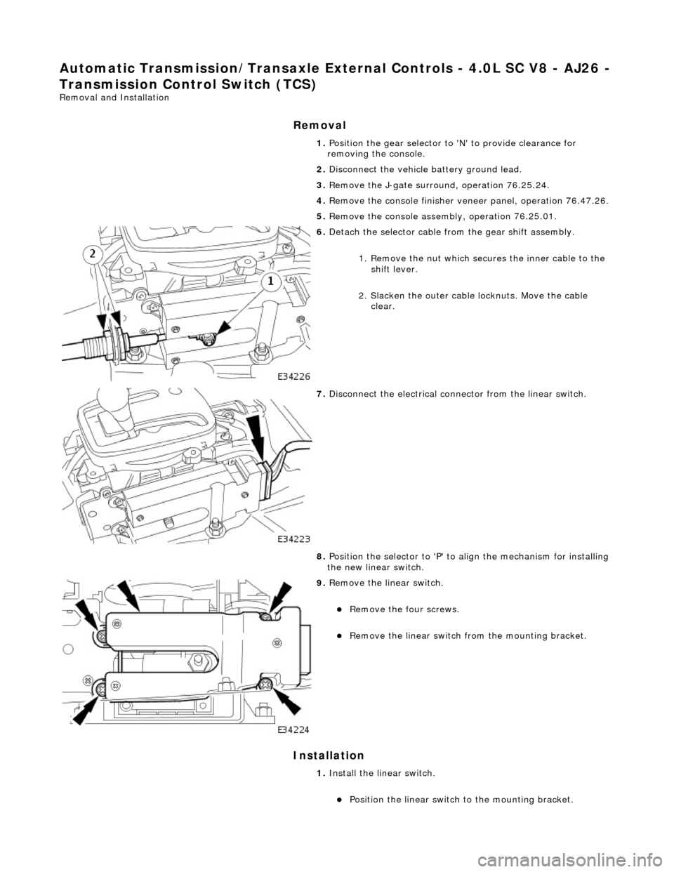
Automatic Transmission/Transaxle External Contro ls - 4.0L SC V8 - AJ26 -
Transmission Control Switch (TCS)
Removal and Installation
Removal
Installation
1. Position the gear selector to 'N' to provide clearance for
removing the console.
2. Disconnect the vehicle battery ground lead.
3. Remove the J-gate surroun d, operation 76.25.24.
4. Remove the console finisher vene er panel, operation 76.47.26.
5. Remove the console assembly, operation 76.25.01.
6. Detach the selector cable from the gear shift assembly.
1. Remove the nut which secures the inner cable to the shift lever.
2. Slacken the outer cable locknuts. Move the cable clear.
7. Disconnect the electrical conne ctor from the linear switch.
8. Position the selector to 'P' to align the mechanism for installing
the new linear switch.
9. Remove the linear switch.
Remove the four screws.
Remove the linear switch fro m the mounting bracket.
1. Install the linear switch.
Position the linear switch to the mounting bracket.